Baicells Nova436Q Installation Manual
Hide thumbs
Also See for Nova436Q:
- Installation manual (29 pages) ,
- Installation manual (28 pages) ,
- Installation manual (45 pages)

Related Manuals for Baicells Nova436Q


Summary of Contents for Baicells Nova436Q
- Page 1 Nova436Q Outdoor 4x1W Two-Carrier TDD eNodeB Installation Guide QRTB 2.9.4 March 2022 Version 1.16...
- Page 2 About This Document This document is intended for personnel who will be installing the Baicells Nova436Q Outdoor 4x1W Two-Carrier Time Division Duplexing (TDD) eNodeB (eNB) product. The product overview is followed by the procedures for properly installing, performing basic configuration, and verifying the eNB is operational.
- Page 3 Resources • Documentation - Baicells product data sheets, this document, and other technical manuals can be found at Baicells.com > Resources > Documents. Support - How to open a support ticket, process an RMA, and the Support Forum are at •...
-
Page 4: Table Of Contents
Table of Contents 1 Overview ..........................7 1.1 Introduction ........................7 1.2 Features......................... 8 2 Installation Preparation ......................10 2.1 Materials ........................10 2.2 LEDs and Interfaces ...................... 11 2.3 Location and Environment ................... 12 2.4 Grounding and Lightning Protection ................13 2.5 Weatherproofing ...................... - Page 5 Appendix: Regulatory Compliance .................... 39 FCC Compliance ......................... 39 ISEDC Compliance ......................39 List of Figures Figure 1-1: Nova436Q eNB ......................7 Figure 1-2: Network Structure ..................... 7 Figure 2-1: Packout ........................10 Figure 2-2: LEDs and Interfaces ....................11 Figure 2-3: Weatherproofing .....................
- Page 6 Figure 3-13: Connecting Cables and Grounding Screws .............. 23 Figure 3-14: Check LEDs ......................24 Figure 3-15: GUI Login ....................... 25 Figure 3-16: Home Page ......................26 Figure 3-17: Configuration Flow ....................27 Figure 3-18: WAN/LAN/VLAN ....................28 Figure 3-19: LGW ........................30 Figure 3-20: LGW = Router......................
-
Page 7: Overview
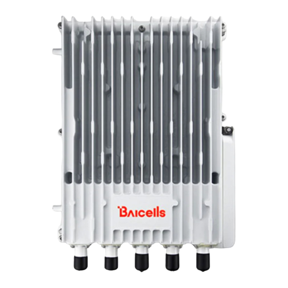
Overview 1.1 Introduction The Baicells Nova436Q (Figure 1-1) is an advanced outdoor 4x1W two-carrier eNodeB (eNB) that is compliant with Third-Generation Partnership Program (3GPP) on Long-Term Evolution (LTE) Time Division Duplexing (TDD) technology. This versatile eNodeB can be configured as a 2x1W single carrier eNB, two 2x1Ws single carrier eNBs (Dual Carrier/Split Sector), or a 4x1W Carrier Aggregation (CA) eNB. -
Page 8: Features
Baicells provides FCC Part 96 certified eNBs, including the Nova436Q, and CPEs that operate within the Part 96 rules for CBRS. The Baicells eNBs and CPEs use a Domain Proxy (DP) to connect to the SAS server by leveraging the existing connection with the OMC. - Page 9 HaloB User Guide • SAS Deployment Guide In addition to the Nova436Q eNB's two carriers and multiple operating modes, following is a list of other key features. The Nova436Q datasheet providing technical specifications is kept up-to- date on the Baicells website.
-
Page 10: Installation Preparation
Installation Preparation 2.1 Materials Check the Nova436Q package to ensure it contains the primary components in the packout (Figure 2-1). In addition to industry-standard tools, you will need the materials described in Table 2-1 and the tools shown in Table 2-2. -
Page 11: Leds And Interfaces
Table 2-2: Installation Tools Level bar Marker pen Knife Pliers Percussion drill and Phillips-head Wrench Hammer drill heads screwdriver 0.05 cm (5 mm) Cable vice Tape measure T7 screwdriver head L-shape Allen wrench (crimper) 2.2 LEDs and Interfaces Figure 2-2, Table 2-3, and Table 2-4 explain the eNB's LED status indicators and interfaces. Figure 2-2: LEDs and Interfaces... -
Page 12: Location And Environment
Port for external RF antenna, N-female connector 2.3 Location and Environment The Nova436Q can be installed on a pole or a wall. For the best signal coverage, place the eNB in an unobstructed location. In addition to network planning, when determining where to place the eNB you need to consider factors such as climate, hydrology, geology, the possibility of earthquakes, reliable electric power, and transportation access. -
Page 13: Grounding And Lightning Protection
2.4 Grounding and Lightning Protection You must protect the eNB, antenna, and GPS against lightning. All Nova eNBs have a floating ground on the power system. Following are guidelines concerning grounding. The yellow-green ground wire must be at least 5 AWG (16 mm ) diameter. -
Page 14: Cloudcore Account
The last layer should be tight enough to keep it from cracking. 2.6 CloudCore Account The Baicells CloudCore includes the Evolved Packet Core (EPC), managed by Baicells, and two operator applications, Operations Management Console (OMC) to manage network elements and Business and Operation Support System (BOSS) to manage subscribers. -
Page 15: Installation
Installation 3.1 Process Overview Figure 3-1 provides an overview of the installation process. Figure 3-1: Installation Process Overview 3.2 Install GPS Antenna WARNING: Ensure the antenna is connected before powering up the eNB. The wireless signal transmission power can cause bodily injury and damage to the eNB and RF power amplifier devices. -
Page 16: Install Enb On Pole Or Wall
GPS antenna feeders cannot be grounded together with ground conductors of interfering equipment such as air conditioners, motors, and pump motors, etc. to prevent external interference from being introduced into the antenna system. Figure 3-2: GPS Installation Requirements The GPS antenna system is assembled in manufacturing before packing. The only installation step is to fix the GPS mounting bracket on the eNB with the M4*14 screws (Figure 3-3). -
Page 17: Figure 3-4: Omega Clamps
Check to ensure the diameter of the pole is in the range of 1.6–3.9 in (40–100 mm). The position of the eNB on the pole should be at least 47 in (120 cm) in height. Follow the steps below to install the eNB on a pole. -
Page 18: Install On Wall
4. Tighten the bolt on the top of the bracket using a Phillips-head screwdriver to complete the installation (Figure 3-7). Figure 3-7: Completed Attachment 3.3.2 Install on Wall Ensure that the wall can bear at least four times the weight of the eNB. Follow the steps below to install the Nova436Q eNB on the wall. -
Page 19: Figure 3-8: Mark And Drill Holes
1. Take apart the assembled installation bracket. 2. Place the installation bracket on the wall with the arrow facing upward, as shown in Figure 3-8. Mark the drilling locations using a pencil or marker. 3. Drill two holes in the wall to match the size of the wall bracket holes. Figure 3-8: Mark and Drill Holes 4. -
Page 20: Connect Cables
5. Using the two pins on the bracket on the back of the eNB, attach the eNB to the mounting bracket on the wall. Push the eNB until the hook is firmly attached to the mounting bracket. Tighten the bolt on the top of the bracket using a Phillips-head screwdriver to complete the installation (Figure 3-10). -
Page 21: Connect Gps Antenna Cable
3.4.2 Connect GPS Antenna Cable WARNING: Ensure the antenna is connected before powering up the eNB. The wireless signal transmission power can cause bodily injury and damage to the eNB and RF power amplifier devices. Insert the GPS jumper into a cold shrink tube. Connect one end of the GPS jumper to the GPS antenna. -
Page 22: Connect Ground Cable
Prepare the grounding cable according to the actual measurements and requirements of the specific installation site. The Nova436Q eNB has two grounding screws located on the bottom of the unit (Figure 3-12). Follow the steps below the figure to connect the ground cable. -
Page 23: Figure 3-12: Grounding Screws
Figure 3-12: Grounding Screws 1. Unscrew one grounding screw, connect one end of the ground cable to the grounding screw, and retighten the screw. 2. Repeat step 1 for the second grounding screw. 3. Once the eNB is installed at the outdoor location, the other end of the ground cable needs to connect to a good earth grounding point (Figure 3-13). -
Page 24: Power On To Check Led Status
Reference: eNodeB Configuration Guide The Nova436Q eNB can be configured in Single Carrier (SC), Carrier Aggregation (CA), or Dual Carrier (DC)/split mode, depending on which licenses you have purchased, and/or in HaloB mode, which is embedded in the base software. The Nova436Q also supports CBRS SAS operation. -
Page 25: Launch The Enb Gui
3.6.1 Launch the eNB GUI Follow the steps below to connect to the GUI. Step 1: Use an Ethernet cable to connect the eNB DATA port to the local network routed to the Internet. The DATA interface is set to DHCP client by default. Optionally, you can plug a PC directly into the eNB MGMT port. -
Page 26: Upgrade Firmware
3.6.2.1 Upgrade Firmware from eNB GUI 1. Download the most recent firmware file from Baicells.com > Support > Firmware, and save on local computer. 2. Go to System > Upgrade, and select whether to preserve the current settings. -
Page 27: Basic Configuration Overview
3.6.2.2 Upgrade Firmware from the OMC 1. Go to eNB > Upgrade > Upgrade&Rollback. 2. Select the correct Product Type from the list. 3. Select the checkbox next to the eNB(s) you want to upgrade. 4. In the New Task window, select the Upgrade Type. 5. -
Page 28: Configure Network Interfaces
3.6.4 Configure Network Interfaces The network interfaces defined as part of the initial, basic setup include the WAN/LAN/VLAN interfaces, Dynamic Host Configuration Protocol (DHCP), and the Local Gateway (LGW) mode. 3.6.4.1 WAN/LAN/VLAN Go to the Network > WAN/LAN/VLAN menu (Figure 3-18). The WAN interface is an external communication portal (Internet connection) between the eNB's Network Management System (NMS) –... -
Page 29: Table 3-1: Wan/Lan/Vlan
Table 3-1: WAN/LAN/VLAN Field Name Description Allow Enable or disable the Local Maintenance Terminal connection through the Management WAN port. Access Over WAN Connect Type Used to select the type of connection for the eNB (Copper or Fiber) Used to specify the maximum size of the network layer protocol data unit that can be communicated in a single network transaction. -
Page 30: Figure 3-19: Lgw
3.6.4.2 LGW The Local GateWay (LGW) setting must be configured when using the Baicells CloudCore Evolved Packet Core (EPC). Refer to Figure 3-19 and Table 3-2. You must reboot the eNB when you make changes to these settings. Figure 3-19: LGW... -
Page 31: Figure 3-20: Lgw = Router
Field Name Description First Address If LGW Mode = Router and Static Address = ON (Figure 3-20), enter the first static IP address in the range. Last Address If LGW Mode = Router and Static Address = ON (Figure 3-20), enter the last static IP address in the range. -
Page 32: Configure The Management Server
In the BTS Setting > Management Server window you will enter the network management service (NMS) information (Figure 3-22). When using the Baicells CloudCore to manage the network, in the http:// field enter the following URL address and port number: baiomc.cloudapp.net:48080/smallcell/AcsService... -
Page 33: Figure 3-22: Management Server
Enter the management server IP address and port number CloudKey Operators using the Baicells CloudCore are provided a unique CloudKey identifier that can be used when configuring CPEs and eNBs. If entered in this field, when the device is powered on it will immediately associate to the operator's OMC account. -
Page 34: Configure Quick Settings
Frequency will auto-fill based on the eNB hardware model. Make sure the Cloud EPC field is set to ON when using the Baicells CloudCore. If you are testing the eNB in a lab environment, turn the power down as low as it will go under the Power Modify field. -
Page 35: Configure Carrier Setting
Carrier Aggregation & Dual Carrier (Split Mode) Configuration Guide The Carrier Setting menu is used only in the two-carrier Nova436Q eNB (Figure 3-24). You can set the eNB to run as a single carrier, as two combined carriers using Carrier Aggregation (CA), or as two independent carriers using Dual Carrier (DC)/split mode, depending on which licenses you have purchased. -
Page 36: Reboot
Figure 3-24: Carrier Setting 3.6.8 Reboot Once the basic configuration settings are saved, reboot the eNB. There are two options for rebooting in the eNB GUI. From the landing page of the eNB GUI, navigate to System > Reboot, or select Reboot under the Welcome banner (Figure 3-25). -
Page 37: Verify Enb Operational Status
3.6.9 Verify eNB Operational Status When the eNB is finished rebooting, check the eNB status using the eNB GUI and the OMC. Once the eNB is mounted at its intended destination and powered on, recheck the status settings. eNB GUI: Go to Basic Setting > Basic Info, and check the Cell Status field (Figure 3-26). It •... -
Page 38: Figure 3-28: Omc > Enb > Monitor > Display Setting
Figure 3-28: OMC > eNB > Monitor > Display Setting Before commercial operation, Baicells recommends implementing cell site acceptance testing of a new site to ensure the service meets expectations, to document network speeds at various locations in the cell, and to verify RF coverage. -
Page 39: Appendix: Regulatory Compliance
Appendix: Regulatory Compliance FCC Compliance This device complies with part 15 of the FCC Rules. Operation is subject to the following two conditions: (1) This device may not cause harmful interference, and (2) this device must accept any interference received, including interference that may cause undesired operation. Any Changes or modifications not expressly approved by the party responsible for compliance could void the user's authority to operate the equipment.