Cisco NCS 540 Installation Manual
Small density passive cooled routers
Hide thumbs
Also See for NCS 540:
- Hardware installation manual (80 pages) ,
- Prepare for installation (14 pages) ,
- Manual (14 pages)
Table of Contents
Advertisement
Quick Links
Advertisement
Table of Contents

Related Manuals for Cisco NCS 540


Summary of Contents for Cisco NCS 540
- Page 1 Cisco Network Convergence System 540 Passive Cooled Small Density Routers Hardware Installation Guide First Published: 2022-04-29 Americas Headquarters Cisco Systems, Inc. 170 West Tasman Drive San Jose, CA 95134-1706 http://www.cisco.com Tel: 408 526-4000 800 553-NETS (6387) Fax: 408 527-0883...
- Page 2 Cisco and the Cisco logo are trademarks or registered trademarks of Cisco and/or its affiliates in the U.S. and other countries. To view a list of Cisco trademarks, go to this URL: https://www.cisco.com/c/en/us/about/legal/trademarks.html.
-
Page 3: Table Of Contents
Safety Precautions for Module Installation and Removal Safety with Electricity Power Supply Considerations Preventing ESD Damage Site Planning General Precautions Site Planning Checklist Site Selection Guidelines Environmental Requirements Physical Characteristics Clearance Guidelines Cisco Network Convergence System 540 Passive Cooled Small Density Routers Hardware Installation Guide... - Page 4 Connect the Router to the Network Install the Front Cover C H A P T E R 4 Appendix LEDs Router LEDs Power Status LEDs Combination of LEDs SFP SFP+ Port LED Cisco Network Convergence System 540 Passive Cooled Small Density Routers Hardware Installation Guide...
- Page 5 RJ-45 ToD or 1-PPS Port Pinouts Console Port Pinouts Alarm Port Pinouts USB Port Console Pinouts USB Port Memory Pinouts Management Ethernet Port Pinouts GPS Port Pinouts Cisco Network Convergence System 540 Passive Cooled Small Density Routers Hardware Installation Guide...
- Page 6 Contents Cisco Network Convergence System 540 Passive Cooled Small Density Routers Hardware Installation Guide...
-
Page 7: Cisco Ncs 540 Small Density Passive Cooled Routers Overview
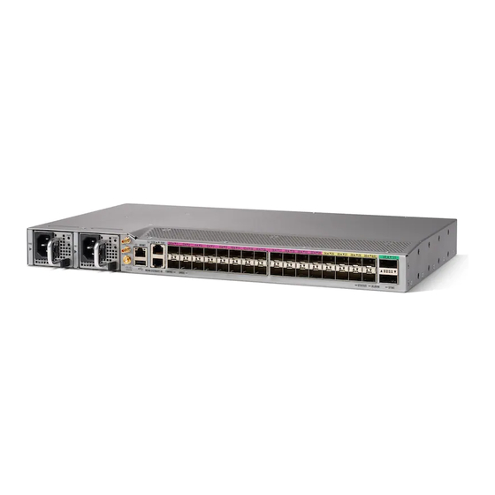
Cisco NCS 540 Small Density Passive Cooled Routers Overview The Cisco NCS 540 Small Density Passive Cooled Router is temperature-hardened, fixed port, 2.5 rack unit form-factor router. An IOS XR based cell site router, the router extends Cisco’s 5G Converged SDN Transport to edge of the networks as a CSR/NID/CPE, with the smallest footprint, ever. -
Page 8: Cisco Ncs 540 Small Density Passive Cooled Router Features
Ports 4 X 1G Copper Ports 1G ports (Ports 4-19) (Ports 0-3) 6 X 10G SFP ports (Ports 1 PPS 20-25) USB Memory ToD and Console Ports Cisco Network Convergence System 540 Passive Cooled Small Density Routers Hardware Installation Guide... -
Page 9: Specification
Cisco NCS 540 Small Density Passive Cooled Routers Overview Specification Specification For information on physical specification, temperature, and other details for the router, see Cisco NCS 540 chassis specification in the Cisco Network Convergence System 540 Small Density Router Data Sheet. -
Page 10: Console
The RS232 console port provides transmission (Tx), reception (Rx), and ground (Gnd). USB Console A single USB 2.0 Type-A receptacle on the front panel of the router provides console access to uboot, Cisco IOS-XR and diagnostics. While it uses the Type-A connector, it operates as a USB peripheral only for connection to an external host computer. -
Page 11: Preparing For Installation
C H A P T E R Preparing for Installation This chapter describe how to prepare for the installation of the Cisco N540-6Z14S-SYS-D router at your site, and contains the following sections: • Safety Guidelines, on page 5 • Site Planning, on page 10... -
Page 12: Safety Guidelines For Personal Safety And Equipment Protection
• Do not work alone if potentially hazardous conditions exist. • Do not perform any action that creates a potential hazard to people or makes the equipment unsafe. Cisco Network Convergence System 540 Passive Cooled Small Density Routers Hardware Installation Guide... -
Page 13: Safety Precautions For Module Installation And Removal
DC-input power source wire extends from the connector(s) or terminal block(s). Statement 122 Warning Do not work on the system or connect or disconnect cables during periods of lightning activity. Statement 1001 Cisco Network Convergence System 540 Passive Cooled Small Density Routers Hardware Installation Guide... - Page 14 This equipment must be grounded. Never defeat the ground conductor or operate the equipment in the absence of a suitably installed ground conductor. Contact the appropriate electrical inspection authority or an electrician if you are uncertain that suitable grounding is available. Statement 1024 Cisco Network Convergence System 540 Passive Cooled Small Density Routers Hardware Installation Guide...
- Page 15 • Before doing the following, disconnect all power: • Working on or near power supplies • Installing or removing a router chassis or network processor module • Performing most hardware upgrades Cisco Network Convergence System 540 Passive Cooled Small Density Routers Hardware Installation Guide...
-
Page 16: Power Supply Considerations
For the safety of your equipment, periodically check the resistance value of the antistatic wrist strap. It should be between 1 and 10 Mohm. Site Planning The following sections describe how to plan for the installation of the router: Cisco Network Convergence System 540 Passive Cooled Small Density Routers Hardware Installation Guide... -
Page 17: General Precautions
The router is designed to meet the industry EMC, safety, and environmental standards described in the Regulatory Compliance and Safety Information for the Cisco NCS 540 Series Router document. Environmental Requirements Environmental monitoring of the router protects the system and components from damage that is caused by excessive voltage and temperature conditions. -
Page 18: Physical Characteristics
Physical Characteristics Be familiar with the physical characteristics of the router to assist you in placing the system in the proper location. For more information, see the Cisco Network Convergence System 540 Small Density Passive Cooled Routers Datasheet. Clearance Guidelines The router is a passive-cooled equipment with no fans. - Page 19 • To ensure thermal performance of the product in a horizontal mounting orientation, an airflow of 1 m/s must be maintained around the product as shown in above figure. Cisco Network Convergence System 540 Passive Cooled Small Density Routers Hardware Installation Guide...
-
Page 20: Floor Loading Considerations
Ensure that the floor under the rack supporting the routers is capable of supporting the combined weight of the rack and all the other installed equipment. To assess the weight of a fully configured routers, see the Cisco Network Convergence System 540 Small Density Passive Cooled Routers Datasheet. -
Page 21: Electrical Circuit Requirements
Install only in accordance with national and local wiring regulations. Note The Cisco N540-6Z14S-SYS-D routers installation must comply with all the applicable codes, and is approved for use with copper conductors only. The ground bond-fastening hardware should be of compatible material and preclude loosening, deterioration, and electrochemical corrosion of hardware and joined material. -
Page 22: Asynchronous Terminal Connections
For information about the electrode magnetic compliance standards supported on the Cisco N540-6Z14S-SYS-D routers, see the Regulatory Compliance and Safety Information for the Cisco NCS 540 Series Router document. Radio Frequency Interference When electromagnetic fields act over a long distance, Radio Frequency Interference (RFI) may be propagated. -
Page 23: Rack-Mounting Guidelines
The placement of a rack can affect personnel safety, system maintenance, and the system’s ability to operate within the environmental characteristics. Choose a proper location for the router by following the guidelines described here. Cisco Network Convergence System 540 Passive Cooled Small Density Routers Hardware Installation Guide... -
Page 24: Installation Checklist
Installation Checklist copied Site Log established and background information entered Site power voltages verified Site environmental specifications verified Required passwords, IP addresses, device names, and so on, available Cisco Network Convergence System 540 Passive Cooled Small Density Routers Hardware Installation Guide... -
Page 25: Creating A Site Log
You need the following tools and equipment to install and upgrade the router and its components: • ESD-preventive cord and wrist strap • Antistatic mat or antistatic foam • Number 1 and Number 2 Phillips-head screwdrivers Cisco Network Convergence System 540 Passive Cooled Small Density Routers Hardware Installation Guide... - Page 26 • Wire-stripping tools for stripping both 6-AWG and 14-AWG wires • Tape measure and level Warning Only trained and qualified personnel should be allowed to install or replace this equipment. Statement 49 Cisco Network Convergence System 540 Passive Cooled Small Density Routers Hardware Installation Guide...
-
Page 27: Unpacking And Verifying The Shipped Contents
Unpacking and Verifying the Shipped Contents Figure 5: Shipping Contents of the Router When you receive your chassis, perform the following steps: 1. Inspect the box for any shipping damage. If there is obvious physical damage, contact your Cisco service representative. 2. Unpack the router. - Page 28 Preparing for Installation Unpacking and Verifying the Shipped Contents Cisco Network Convergence System 540 Passive Cooled Small Density Routers Hardware Installation Guide...
-
Page 29: Install The Cisco N540-6Z14S-Sys-D Routers
The following sections describe how to install the router in a rack. The procedures in this section apply to both horizontal and vertical mounting of the router in a rack. Cisco Network Convergence System 540 Passive Cooled Small Density Routers Hardware Installation Guide... -
Page 30: Install The Chassis Brackets
Install the cable guides along with rackmount brackets to install the router in a 19-inch EIA rack. See Attaching the Cable Guides. To install the router chassis in the equipment rack, perform these steps: 1. Insert the rear of the chassis between the mounting posts. Cisco Network Convergence System 540 Passive Cooled Small Density Routers Hardware Installation Guide... - Page 31 4. Use a tape measure and level to verify that the chassis is installed straight and level. Cisco Network Convergence System 540 Passive Cooled Small Density Routers Hardware Installation Guide...
-
Page 32: Attach The Cable Guides
1. Position the cable guide-left and cable guide-right against the front of the chassis and align the four screw holes, as shown in figure below. Figure 9: Cable Guide Installation For 19-inch Rack Brackets Cisco Network Convergence System 540 Passive Cooled Small Density Routers Hardware Installation Guide... -
Page 33: Connect The Chassis Ground And Power
Before you connect the power or turn on power to the router, you must provide an adequate chassis ground (earth) connection to your router. Ground the Router The router provides a grounding point on either side of the unit for a two-hole lug. Cisco Network Convergence System 540 Passive Cooled Small Density Routers Hardware Installation Guide... - Page 34 The following figure shows one of the grounding points of the router, for ease of installation. The other grounding point is on the front panel, which can also be used for grounding the router. Cisco Network Convergence System 540 Passive Cooled Small Density Routers Hardware Installation Guide...
- Page 35 3. If your ground wire is insulated, use a wire-stripping tool to strip the ground wire to 0.5 inch ± 0.02 inch (12.7 mm ±0.5 mm) for the ring terminal (see the following figure). Cisco Network Convergence System 540 Passive Cooled Small Density Routers Hardware Installation Guide...
-
Page 36: Power Connection Guidelines
7. Connect the other end of the ground wire to a suitable grounding point at your site. Power Connection Guidelines This section provides guidelines for connecting the router power supplies to the site power source. Cisco Network Convergence System 540 Passive Cooled Small Density Routers Hardware Installation Guide... -
Page 37: Assemble And Connect The Dc Power Cable To The Router
1. There is a DC cover over the DC power supply. Remove the screws to remove the DC terminal block protection cover. 2. The four lugs are provided in the accessories kit. The lugs are in turn connected with the wires. Cisco Network Convergence System 540 Passive Cooled Small Density Routers Hardware Installation Guide... - Page 38 3. Crimp the lugs to the wires. Fix the lugs to the terminal block and then fix the terminal block protection cover. Figure 14: Connect the DC Power Cable to the Router Four Lugs DC Terminal Block Protection Cover Screws Cisco Network Convergence System 540 Passive Cooled Small Density Routers Hardware Installation Guide...
- Page 39 If you are connecting a redundant DC power supply, it is recommended that each power supply be connected to a separate power source in order to prevent power loss in the event of a power failure. Cisco Network Convergence System 540 Passive Cooled Small Density Routers Hardware Installation Guide...
-
Page 40: Install And Remove Sfp Modules
Use only Cisco SFP modules on the Cisco router. Each SFP module has an internal serial EEPROM that is encoded with security information. This encoding provides a way for Cisco to identify and validate that the SFP module meets the requirements for the router. - Page 41 Cisco Network Convergence System 540 Passive Cooled Small Density Routers Hardware Installation Guide...
-
Page 42: Connect To The 10/100/1000 Ports
If the port LED turns Yellow, the device at the other end might not be turned on, or there might be a cable problem or a problem with the adapter installed in the attached device. Cisco Network Convergence System 540 Passive Cooled Small Density Routers Hardware Installation Guide... -
Page 43: Connect The Router To The Network
The following sections describe how to connect a router to the network: Note Connect only SELV services to all the router ports. Connect Console Cables The following sections describe how to connect to the router using console cables: Cisco Network Convergence System 540 Passive Cooled Small Density Routers Hardware Installation Guide... - Page 44 This procedure describes how to connect a Mac OS X system USB port to the console using the built-in OS X terminal utility. 1. Use the Finder to choose Applications > Utilities > Terminal. Cisco Network Convergence System 540 Passive Cooled Small Density Routers Hardware Installation Guide...
- Page 45 Tools and Resources Download Software site, USB Console Software category, at: https://software.cisco.com/download/home/286037604/type/282855122/release/3.13 Note To download the driver, you must have a valid service contract associated to your Cisco.com profile. 1. Unzip the file asr-9xx_usbconsole_drivers.zip. 2. Double-click xrusbser_ver2100_installer.exe in the XR21x141x-Win-DriversOnly-Vers2.1.0.0/EXE folder.
- Page 46 1. Connect the USB end of the USB-to RJ-45 cable to the EIA Console port. 2. Connect the RJ-45 end of the DB-9 adapter cable to the USB-to RJ-45 cable, as shown in figure below. Cisco Network Convergence System 540 Passive Cooled Small Density Routers Hardware Installation Guide...
- Page 47 When in a fixed-speed configuration and MDI mode: • Use a crossover cable to connect to an MDI port • Use a straight-through cable to connect to an MDI-X port Cisco Network Convergence System 540 Passive Cooled Small Density Routers Hardware Installation Guide...
- Page 48 The Flash memory module can be inserted only one way, and can be inserted or removed regardless of whether the router is powered up or not. Figure below shows the USB port connector on the router. Figure 20: Router Flash Token Memory Stick Cisco Network Convergence System 540 Passive Cooled Small Density Routers Hardware Installation Guide...
- Page 49 2. Pull the memory stick from the USB port. 3. To replace the Cisco USB Flash memory stick, simply insert the module into the USB port labeled USB MEM, as shown in router Flash Token Memory Stick figure. The Flash memory module can be inserted only one way, and can be inserted or removed regardless of whether the router is powered up or not.
-
Page 50: Install The Front Cover
1. Connect one end of the cable to the Gigabit Ethernet port on the router. 2. Connect the other end to the BTS patch or demarcation panel at your site. Connect Cables to SFP Modules For information on connecting cables to Cisco optical and Ethernet SFP interfaces, see: http://www.cisco.com/en/US/partner/products/hw/modules/ps5455/prod_installation_guides_list.html. Install the Front Cover The front cover protects the system from dust. -
Page 51: Appendix
This section lists the LEDs of the router. Router LEDs All the data port LEDs in the Cisco N540-6Z14S-SYS-D router are at the front panel. There are five LEDs that reflect the different statuses of the system. Table 4: Router LED Descriptions... - Page 52 Time core is synchronized to an external source including IEEE1588. Flashing Green System is in Synchronous Ethernet mode. Amber Acquiring state or Holdover: Time core is in acquiring state or holdover mode. Cisco Network Convergence System 540 Passive Cooled Small Density Routers Hardware Installation Guide...
-
Page 53: Power Status Leds
Table 7: SFP and SFP+ Port LEDs LED Label Color Status STATUS Admin is down Green Link is up in 1G/10G ports. Yellow Fault or Error or Link Down Cisco Network Convergence System 540 Passive Cooled Small Density Routers Hardware Installation Guide... -
Page 54: Management Port Leds
Link is up in full duplex Link is up in half duplex System Specifications Certain troubleshooting aids of the Cisco NCS 540 enable you to perform these tasks that assist the troubleshooting process: Weight and Power Consumption For information on physical specifications and power consumption, see table Cisco NCS 540 chassis... -
Page 55: Transceiver And Cable Specifications
Description 1PPS_N Output or Input 1PPS RS422 signal 1PPS_P Output or Input 1PPS RS422 signal TOD_N Output or Input Time-of-Day character TOD_P Output or Input Time-of-Day character Cisco Network Convergence System 540 Passive Cooled Small Density Routers Hardware Installation Guide... -
Page 56: Console Port Pinouts
Table 11: Alarm Port Pinouts Signal Name Description ALARM1_IN Alarm input 1 ALARM2_IN Alarm input 2 ALARM3_IN Alarm input 3 ALARM4_IN Alarm input 4 ALARM_I_COMMON Alarm input COM Cisco Network Convergence System 540 Passive Cooled Small Density Routers Hardware Installation Guide... -
Page 57: Usb Port Console Pinouts
An SNMP trap is sent for every external alarm that is raised or cleared on the system. USB Port Console Pinouts This table summarizes the USB port console pinouts: Cisco Network Convergence System 540 Passive Cooled Small Density Routers Hardware Installation Guide... -
Page 58: Usb Port Memory Pinouts
Management Ethernet Port Pinouts This table summarizes the management ethernet port pinouts: Table 15: Management Ethernet Port Pinouts Signal Name TRP0+ TRP0– TRP1+ TRP2+ TRP2– TRP1– TRP3+ TRP3– Cisco Network Convergence System 540 Passive Cooled Small Density Routers Hardware Installation Guide... -
Page 59: Gps Port Pinouts
Output— > 2.2 volts p-p Output— > 2.5V Impedance 50 ohms 50 ohms Pulse Width 50% duty cycle 50% duty cycle Rise Time Input—AC coupled Output—5 nanoseconds Cisco Network Convergence System 540 Passive Cooled Small Density Routers Hardware Installation Guide... - Page 60 Appendix GPS Port Pinouts Cisco Network Convergence System 540 Passive Cooled Small Density Routers Hardware Installation Guide...
- Page 61 (warning) preventing overheating coaxial cable commands show environment restricted access (warning) RJ-45 connectors RS-232 asynchronous data electrical wiring requirements show environment command site requirements, rack-mounting Cisco Network Convergence System 540 Passive Cooled Small Density Routers Hardware Installation Guide IN-1...
- Page 62 INDEX Cisco Network Convergence System 540 Passive Cooled Small Density Routers Hardware Installation Guide IN-2...