
Related Manuals for Hitachi EC702MP-BB3


Summary of Contents for Hitachi EC702MP-BB3
- Page 1 E-Compact MP-BB3 Series Operation Manual UHF Digital TV Transmitters ATSC 3.0: 420 Watts RMS ATSC 1.0: 500 Watts RMS E-Compact Medium Power Series EC702MP-BB3 EC704MP-BB3 Read before handling the equipment. 1 | 108...
- Page 2 E-Compact MP-BB3 Series W A R N I N G All rights are reserved to Hitachi Kokusai Electric Comark LLC, thus any reproduction, adaptation, translation, or misuse of this Manual without prior written permission is prohibited, except as permitted by copyright laws.
-
Page 3: Table Of Contents
E-Compact MP-BB3 Series CONTENTS 1. Index CONTENTS ......................3 Index ................................3 Abbreviations ..............................7 About this Manual ............................8 Basic Knowledge Required ........................... 9 Structure ................................9 Section 1 - Care, Warranty, and Service ....................... 10 Care and Safety ............................10 Warranty ................................ - Page 4 3.1. Single drive, Dual drive (optional) and touch screen display (optional) ........24 3.2. EC702MP-BB3 / EC704MP-BB3 ......................25 3.6.1. MP-BB3 1-PSU / AC Mains ........................27 3.6.2. PSU Redundancy, AC mains, RF Output Power (TPO) ..............27 Main Modules ..............................28 4.1.
- Page 5 E-Compact MP-BB3 Series Homepage features ..........................57 Alarms ............................... 58 Log Alarms ..............................58 Setup ................................59 Power Setup ............................59 Transmitter Setup ..........................60 PA Temperature Control ........................60 Time and Date Setup ..........................60 Alarm Mask ............................61 Exciter ..............................
- Page 6 E-Compact MP-BB3 Series Inspection..............................87 Installation Recommendations........................87 3.1. Preventive Protection .......................... 87 3.2. Tower ..............................87 3.3. Fastening of cables, antennas and connectors ................88 3.4. Indoors Equipment Installation......................89 3.5. Equipment Grounding ......................... 89 3.6. Electric Installation Grounding ......................90 3.7.
-
Page 7: Abbreviations
DVB-S Digital Video Broadcasting – Satellite DVB-S2 Digital Video Broadcasting – Satellite – 2nd generation FPGA Field Programmable Gate Array Forward Hitachi Kokusai Linear Internet Protocol ISDB-T Integrated Services Digital Broadcasting Terrestrial (Brazil) ISDB-Tb Integrated Services Digital Broadcasting Terrestrial Liquid Crystal Display... -
Page 8: About This Manual
420 W UHF ATSC 3.0 Transmitter (6-poles filter) 500 W UHF ATSC 1.0 Transmitter (6-poles filter) Hitachi Kokusai Electric Comark LLC recommends that you carefully read this manual before installing or operating the equipment. This manual is intended for use by qualified, trained installers. -
Page 9: Basic Knowledge Required
E-Compact MP-BB3 Series 4. Basic Knowledge Required The mandatory knowledge and skills to operate the equipment are as follows: • Knowledge of RF electronic circuits • Knowledge of electricity and electrical systems • Knowledge of digital electronics • Experience conducting tests and Digital TV signal measurements in ATSC standards •... -
Page 10: Section 1 - Care, Warranty, And Service
Section 1 - Care, Warranty, and Service 1. Care and Safety Never open the device, as there is a risk of electric shock. If necessary, contact Hitachi Service. Before Connecting the Machine to the AC Mains, one must ensure that the grid Voltage meets the equipment’s settings. -
Page 11: Warranty
FCC Bureau(s), including antenna co-location requirements of §1.1307(b)(3). 2. Changes or modifications not expressly approved by Hitachi Kokusai Electric Comark LLC could void the user's authority to operate the equipment. 3. This device complies with part 15 of the FCC Rules. Operation is subject to the following two conditions: (1) This device may not cause harmful interference, and (2) this device must accept any interference received, including interference that may cause undesired operation. -
Page 12: Technical Assistance
Therefore, in case of maintenance please contact: Hitachi Kokusai Electric Comark LLC Phone: (800) 345-9295 / Fax: (413) 998-1194 E-mail: support@comarktv.com While submitting a requestion for assistance, please provide the following information: Customer name, Equipment Part Number, Serial Number, and a brief explanation of the occurrence. -
Page 13: Section 2 - Minimum Installation Requirements
4. Surge suppressors Defects caused by improper installation or failure to comply with the minimum infrastructure requirements for installation and operation of the products will relieve Hitachi Comark of the contractual warranty. 13 | 108... -
Page 14: Introduction
Wire Gauge Wire Gauge Wire Gauge Wire Gauge Typical mm² mm² mm² mm² EC702MP-BB3 4.17 3.31 EC704MP-BB3* 14.3 6.63 4.17 Not available or uncommonly used *EC704MP-BB3 operates on M110 electrical network using two PSUs. The current values specified in the table are according to the load of each phase, which will determine the size of the conductors and protection. -
Page 15: Grounding
E-Compact MP-BB3 Series 2.2. Grounding The grounding system to which the Comark TV transmitter will be attached is suggested to be designed and implemented by a qualified professional. An improper grounding system may jeopardize the equipment as well as the lives-of the professionals working in the shelter. - Page 16 E-Compact MP-BB3 Series Recommendations 1. We recommend that the transmitter "never see" the power grid directly. 2. We recommend the use of online double-conversion UPS and / or Delta- conversion online UPS built with transformer insulation and with power factor correction (PFC). No break example with Isolating Transformer Benefits: These types of UPS bring great protection and insulation to the transmitter due to its design.
- Page 17 E-Compact MP-BB3 Series Nobreak capatibity (cos Φ * η Nobreak Power = PTX * (nobreak) Real Power [W] cos Φ: Transmitter Power Factor Correction η (nobreak) Nobreak efficiency STATIC BYPASS SWITCH RECTIFIER INVERTER BATTERY Double Conversion Online Nobreak STATIC BYPASS SWITCH DELTA TRANSFORMER PRINCIPAL...
-
Page 18: Atmospheric Discharge Protection System
E-Compact MP-BB3 Series 2.5. Atmospheric Discharge Protection System 2.5.1 Lightning rods The Atmospheric Discharge Protection System consists of the lightning rods and their elements. The tower and shelter where the equipment will be installed must be protected against atmospheric discharges by means of lightning arresters. It is important to determine that all ferrous parts and accessories that make up the Atmospheric Discharge Protection System should be galvanized. -
Page 19: Humidity
E-Compact MP-BB3 Series 2.6.2 Humidity Relative air humidity inside the shelter is also considered a critical factor for improved performance and longer equipment life. Comark equipment should operate in dry environments, which can also be achieved using air conditioners. According to the transmission power, the relative humidity inside the shelter should be: •... -
Page 20: Ac Load And Thermal Dissipation Information For Infrastructure Install
E-Compact MP-BB3 Series 2.7 AC Load and Thermal Dissipation Information for Infrastructure Install EC702MP-BB3 1092 2974 EC704MP-BB3 1812 4478 20 | 108... -
Page 21: Section 3 - E-Compact Bb3 Medium Power Series Uhf Digital Tv Transmitters
E-Compact MP-BB3 Series Section 3 – E-Compact BB3 Medium Power Series UHF Digital TV Transmitters 1. Overview The E-Compact High-Power family of air-cooled Doherty solid-state transmitters from Comark was designed specifically for the repack marketplace. Its design is simple, rugged, reliable, and ultra- efficient. -
Page 22: Specifications
⇨ Telemetry through GPRS interface ⇨ Exciter ⇨ GPS time base (exciter's internal module) RF Performance ATSC 3.0 A/300 Modulation Standard ATSC 1.0 A/53 Output Power (Before Filter) EC702MP-BB3 EC704MP-BB3 ATSC 3.0 267 W 508 W ATSC 1.0 321 W 610 W... - Page 23 E-Compact MP-BB3 Series Electrical Features Power Requirement⁴ EC702MP-BB3 EC704MP-BB3 Single-Phase (M110) Single-Phase (M110) for two-PSU (specify configuration at equipment purchase Single-Phase (M220) Single-Phase (M220) order) Biphasic (B220) Biphasic (B220) EC702MP-BB3 EC704MP-BB3 AC Power 100~253VAC (two PSU) For use one or two PSU, see Section 3, topic 3.2.2. PSU...
-
Page 24: Construction
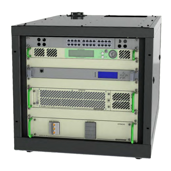
E-Compact MP-BB3 Series 3. Construction The E-Compact family of low power solid-state DTV transmitters provides maximum flexibility for site layout and installation. Transmitters are installed in custom designed 22” wide (19” panel opening) cabinets. Being available in several configurations depending on the output power, the redundancy option implemented, and the number of channels at a given site. -
Page 25: Ec702Mp-Bb3 / Ec704Mp-Bb3
E-Compact MP-BB3 Series 3.2. EC702MP-BB3 / EC704MP-BB3 The transmitter controller is contained in a 1RU chassis and the RF amplifier is contained in a separate 2RU chassis. The digital exciter is 1RU (not provided) for a total of 4RU or 7” of vertical panel space. - Page 26 FBA in ( Exciter ) Control I RF Out Control Module / Exciter Bandpass Filter Lowpass Filter RF Sample block FC6D60C @EC702MP-BB3 MOD 40243 MOD 40 215 FC6D80C @EC702MP-BB3 PA 704 MP Power Amplifier RF Sampl e Comm AC Pow er EIA 1 - 5 / 8 "...
-
Page 27: Mp-Bb3 1-Psu / Ac Mains
OUTPUT POWER OPERATING 100 ~187 VAC 100 ~187 VAC 100% 187 ~253 VAC 187 ~253 VAC 100% EC702MP-BB3 - MAXIMUM PROGRAMMED POWER: 250W (ATSC 1.0) NUMBER OF PSU INPUT VOLTAGE OUTPUT POWER OPERATING 100 ~253 VAC 100% 100 ~253 VAC... -
Page 28: Main Modules
The general structure of an E-Compact transmitter series consists of the following modules: Drawers / Modules: Control Module Power Amplifier MCCB Module CM9001 PA704MP EC702MP-BB3 MOD GV 40288 MOD GV 40335/40336 MOD 40323 EC704MP-BB3 MOD GV 40288 MOD GV 40298/40309... -
Page 29: Control Module Cm9001 (Mod Gv 40288)
E-Compact MP-BB3 Series 4.1. Control Module CM9001 (MOD GV 40288) The E-Compact series of transmitters utilize a dedicated 1RU controller chassis, CM9001. The controller chassis has several functions including: • Access to exciter setup / monitoring • AC mains power monitoring •... -
Page 30: Interfaces
E-Compact MP-BB3 Series 4.6.2. Interfaces Front Panel Description Function Air entrance Air inlet for cooling LCD Display Navigation display Leds Power On Signals power on equipment Up key (▲) Down key (▼) Left key (◀) Display navigation keyboard. Right key (▶) Enter/OK key (OK) Esc key (Esc) On: Indicates the presence of an Alarm. - Page 31 E-Compact MP-BB3 Series AC LINE 90~240VAC (43~63Hz) EXPANSION I/O CONTROL I/O MANAGEMENT RF IN SAMPLE EXCITER CONTROL TERMINAL Description Type Functiom GND Screw Chassis GND connector ON/OFF ON / OFF switch ON/OFF equipment AC LINE INPUT Power Jack AC AC power input EXPANSION 10 pin terminal Expansion to Input / output management and...
-
Page 32: Communication
E-Compact MP-BB3 Series 4.6.3. Communication MAIN EXCITER (not provided) RF: +1dBm Exciter Status CM9001 Communication Control I/O RF OUT EXPANSION I/O 10 pin terminal block +5VCC Analog general purpose Output 0 Analog general purpose Output 1 Analog general purpose input 0 EXPNASION I/O Analog general purpose input 1 Digital general purpose input 0... - Page 33 E-Compact MP-BB3 Series CONTROL I/O 10 pin terminal block External measurement of +8V External measurement of +15V External measurement of +50V External measurement of Forward Power CONTROL I/O External measurement of Reflected Power External RF Power On/Off RS485A for HPA Communication B1 B2 B3 B4 B5 B6 B7 B8 B9 B10 RS485B for HPA Communication A1 A2 A3 A4 A5 A6 A7 A8 A9 A10...
- Page 34 E-Compact MP-BB3 Series 34 | 108...
-
Page 35: Display Interface
E-Compact MP-BB3 Series 4.6.4. Display interface The Control Module CM9001 has a system of configuration, measurements, alarms, and remote management (TELESUPERVISION), that controls all of the transmitter modules. The transmitter configuration can be done either by the front panel of the transmitter or the web interface using a browser of your choice or SNMP. - Page 36 E-Compact MP-BB3 Series DESCRIPTION Current date and time CM9001 IP address for Remote Access (interface WEB) Equipment model controlled by CM9001 Exciter status (OK / Fail) Operation channel Operation digital TV system (ATSC 1.0 / ATSC 3.0) Status CM9001: Single Drive: ---- Dual Drive: (A-active / B-Standby), (A-standby / B-active) Forward power after filter value (Watts) Reflected power value (Watts)
-
Page 37: Equipment Featurings
E-Compact MP-BB3 Series DESCRIPTION Indicates the Submenu to be accessed Functions to access or that are changing in value Select “on” / “off” with the “▶” and“◀” keys. When the function is accessed, to change the value, increase the value with the “▶” key or decrease the value with the “◀” key. Indicates that the Function has been changed and not registered (Not active). -
Page 38: Alarms - Front Panel Signaling And Shortcut Keys
E-Compact MP-BB3 Series RF Power Protection: The reflectometer has accuracy above 10% of the reflected power to react to the equipment reaching or exceeding 20%. Therefore, accuracy in measures of reflected below 10% relative to direct power are not guaranteed. Protection against main voltage variations (Surge): Each part of the equipment has its independent power supply and all feature the same protection characteristics. -
Page 39: System Operation (Display Interface)
E-Compact MP-BB3 Series 4.6.7. System Operation (Display interface) The "Setup" menu allows you to access and change the functions of the equipment's parameter settings: > Equipment > Setup > Measurements > System Alarms / Log > Remote Access > Equipment > Setup: Access to configure equipment parameters >... -
Page 40: Main Menu > Setup > Power
E-Compact MP-BB3 Series > Main Menu > Setup > Power: Control the Equipment Power: MENU PARAMETER DESCRIPTION Mute RF power (on) > RF Mute on / off Enable RF power (off) Power (W) Changes the output power of the Equipment. The >... -
Page 41: Main Menu > Setup > Password Setup
E-Compact MP-BB3 Series > Main Menu > Setup > Password Setup: Set a 5-digit numeric password to access the setup menu by the front panel. MENU PARAMETER DESCRIPTION > Password XXXXX Stores the numeric value of the password > Password ON/OFF On / off Enable or Disable the access password >... -
Page 42: Main Menu > Setup > Temperature
E-Compact MP-BB3 Series MENU PARAMETER DESCRIPTION LDMOS Drain Voltage - The values are pre-set at the > LDMOS Drain Voltage Voltage (V) factory Carrier Amp. Current - The values are pre-set at the > Carrier Amp. Current Current (A) factory Peak Amp. -
Page 43: Main Menu > Measurements
E-Compact MP-BB3 Series Main Menu > Measurements The “Measurements” menu allows access to the equipment's operating parameters (read only). > Measurements > Power > Exciter Status > HPA Drawers > Software > Communication Status > Main Menu > Measurements > Power: Reading of the equipment's power parameters, such as forward power and reflected power, among others: MENU... -
Page 44: Main Menu > Measurements > Hpa Drawers
Identifying HPA Drawers, Power Supplies, and Power Amplifiers (PA) in the menu: Use the ▼ or ▲ keys to toggle between menus Power Supply 2 Power Supply 1 PA IDENTIFICATIONS PA IDENTIFICATIONS DRIVER DRIVER POWER AMPLIFIER DRAWER @EC702MP-BB3 POWER AMPLIFIER DRAWER @EC704MP-BB3 Top View Top View 44 | 108... -
Page 45: Main Menu > Measurements > Hpa Drawers > Rf Power
E-Compact MP-BB3 Series > Main Menu > Measurements > HPA Drawers > RF Power: View the main status of all Power Amplifiers Drawers: Use the ▼ or ▲ keys to toggle between menus MENU PARAMETER DESCRIPTION > Forward Power Power (W) HPA forward output power >... -
Page 46: Main Menu > Measurements > Hpa Drawers > Drain Current
E-Compact MP-BB3 Series MENU PARAMETER DESCRIPTION > Power Supply 1 Voltage (V) Power supply voltage 1 > Power Supply 2 Voltage (V) Power supply voltage 2 > Driver Power Supply Voltage (V) Power supply voltage Driver > Main Menu > Measurements > HPA Drawers > Drain Current: Shows all HPA Drawer drain Currents: Use the ▼... -
Page 47: Main Menu > Measurements > Software
E-Compact MP-BB3 Series > Main Menu > Measurements > Software: Shows the Control Module software version: MENU PARAMETER DESCRIPTION > Software Control Software Control version > Software DIGI Software DIGI version > Main Menu > Measurements > Communication Status: Shows the HPA communication status (ok / fail): MENU PARAMETER DESCRIPTION... -
Page 48: Main Menu > System Alarms/Log
E-Compact MP-BB3 Series Main Menu > System Alarms/Log This menu gives access to information on alarms that are occurring or have occurred in the past, providing a guide for necessary preventive or corrective maintenance. > System Alarms / Log > Current Alarms >... -
Page 49: Main Menu > System Alarms/Log > Alarms/Log
E-Compact MP-BB3 Series See page 49 for the alarms list and their respective meanings. In the absence of alarms, the display will show the following message: > Main Menu > System Alarms/Log > Alarms/Log: Shows the Log alarms list. This function can also be accessed through the “PAST ALARM” key, located on the front panel: The Log Menu has the following structure: DESC. -
Page 50: Main Menu > System Alarms/Log > Drawers Alarms
E-Compact MP-BB3 Series In the absence of alarms, the display will show the following message: > Main Menu > System Alarms/Log > Drawers Alarms: Shows the list of alarms currently occurring. This function can also be accessed through the “FAULT” key located on the front panel: >... -
Page 51: Main Menu > System Alarms/Log > Drawers Alarms > Past Alarms
E-Compact MP-BB3 Series In the absence of alarms, the display will show the following message: > Main Menu > System Alarms/Log > Drawers Alarms > Past Alarms: Shows the Log alarms list. The Log Menu has the following structure: DESC. Amount of existing Logs Log number pointed in order of occurrence - Indicates that the log refers to the start of the alarm... -
Page 52: Main Menu > System Alarms/Log > Drawers Alarms > Clear Past Alarm
E-Compact MP-BB3 Series > Main Menu > System Alarms/Log > Drawers Alarms > Clear Past Alarm: Reset the drawer alarm list. Select “On” to reset the Past Alarms list. Power Amplifiers Drawers (HPA) Alarms List SYSTEM DRAWER ALARM ALARM DESCRIPTION THRESHOLD ACTION PA High Current... -
Page 53: Main Menu > System Alarms/Log > Clear Alarm Log
E-Compact MP-BB3 Series SYSTEM DRAWER ALARM ALARM DESCRIPTION THRESHOLD ACTION Driver Low RF Input Level Driver RF Input is lower than threshold. -8 dBm Notification Driver Temperature is greater than Driver High Temperature 75 ºC (167 °F) Notification threshold. 330W @PA702MP ATSC3.0 HPA Forward Power is greater than 380W @PA702MP ATSC1.0 Critical High Forward Power... -
Page 54: Main Menu > Remote Access
E-Compact MP-BB3 Series Main Menu > Remote Access In this menu the Ethernet network parameters are configured to have remote access via a network connection. All equipment parameters, such as transmit power, source measurements, alarms check, and all possible functional selections can be accessed remotely by a PC Browser or any Smartphone Browser by connecting to the embedded WEB page server inside of the equipment. -
Page 55: Web Interface - Remote Access
E-Compact MP-BB3 Series 4.6.8. WEB Interface – Remote Access Introduction The entire device management and configuration system can be remotely accessed via a browser on any personal computer, tablet, or smartphone. The device embeds an internet server with a dedicated page that allows you to navigate its parameters in an easy way and also make it possible to change its settings in a more friendly graphical environment. - Page 56 E-Compact MP-BB3 Series For ethernet connections, only use static IP settings. For navigation, use a fully updated internet browser. To control the device through the web interface, we recommend Chrome, Firefox Mozilla, and Opera browsers. The equipment can be connected directly to a computer, switcher, or router through the MANAGEMENT port located on its rear panel.
-
Page 57: Homepage Features
E-Compact MP-BB3 Series Homepage features EC704MP-BB3 DESCRIPTION Hides / Displays Side Menu Bar Model Transmitter Equipment name / Channel transmittion Forward Power - Direct Power Monitor in real time Reflected Power - Reflected Power Monitor in real time On / Off Power Section user Exits the WEB Interface Vertical Bar Menu... -
Page 58: Alarms
E-Compact MP-BB3 Series Alarms Shows the list of alarms currently occurring. In the event of alarms, the number of active alarms (Current Alarms) will appear in the sidebar in red. List of alarms Alarm help occurring Log Alarms Shows the list of alarms currently occurring. In the event of alarms, the number of active alarms (Current Alarms) will appear in the sidebar in red. -
Page 59: Setup
E-Compact MP-BB3 Series DESCRIPTION Type alarm (Current / Past alarm) Alarm Description Date / time alarm Clear the entire list. Upon confirming this action, it will no longer be possible to recover the deleted list Download the alarm list to the file named “LogAlarms.csv” in the “Download” folder on your computer Alarm help Indication of the current page and command to switch between the previous or subsequent pages Setup... -
Page 60: Transmitter Setup
E-Compact MP-BB3 Series Transmitter Setup Changes Transmitter Parameters, such as turning the ALC ON or OFF and setting the transmitter name. PA Temperature Control Allows to set the operating temperature of the power amplifiers and set the temperature unit (°C / °F). Time and Date Setup Sets the internal real time clock (RTC) of the equipment: 60 | 108... -
Page 61: Alarm Mask
E-Compact MP-BB3 Series Alarm Mask Sets the reflected power alarm threshold. Exciter Opens the external exciter control and management web. Enter the external exciter IP adress and press connect. Import/Export Import / Export Control Module settings. Press “Download” to save the file “export xx_xx_xx xx_xx_xx.json” in the PC downloads folder. - Page 62 E-Compact MP-BB3 Series Upload a file settings: • Press “Upload” • Select the .json file: • Select the features to import and press save: • Press “OK” when the process is done 62 | 108...
-
Page 63: Measurements
E-Compact MP-BB3 Series Measurements The “Measurements” menu allows the user to access the equipment's operating parameters (read only). Software Version Shows the Control Module’s software version. Power Shows the reading of the equipment's power parameters, such as forward power and reflected power, among others. 4400 4400 2.08... -
Page 64: Communication Status
E-Compact MP-BB3 Series Communication Status Shows the HPA’s communication status. Transistor Bias Shows the transistor DC’s operating voltage or current conditions so that any RF input signal can be amplified correctly by the transistor. Exciter Status Shows the Exciter’s communication status. 64 | 108... -
Page 65: Drawers
E-Compact MP-BB3 Series Drawers View the main status of all Power Amplifiers Drawers (HPA): Drawer Identification: Power Supply 2 Power Supply 1 Individual status of each Drawer (HPA): Power Supply Shows the HPA Power Supply’s status. 65 | 108... -
Page 66: Driver
Shows the HPA Driver’s status. PA IDENTIFICATIONS DRIVER POWER AMPLIFIER DRAWER Top View Power Amplifier Shows the HPA Power Amplifier’s status. PA IDENTIFICATIONS PA IDENTIFICATIONS DRIVER DRIVER POWER AMPLIFIER DRAWER @EC702MP-BB3 POWER AMPLIFIER DRAWER @EC704MP-BB3 Top View Top View 66 | 108... - Page 67 E-Compact MP-BB3 Series Select the status to show Current: 5.89 6.54 6.05 5.99 Temperature: 51.90 50.72 48.81 48.90 VGS Peak: 0.33 0.33 0.33 0.33 67 | 108...
- Page 68 E-Compact MP-BB3 Series VGS Carrier: 1.75 1.70 1.71 1.78 Software Version: 68 | 108...
-
Page 69: Remote
E-Compact MP-BB3 Series Remote Configures the SNMP and Ethernet network parameters to have remote access via a network connection. SNMP Configures SNMP and download MIB table. SNMP Status Download the MIB table (file CMLinearMIB.zip) in PC SNMP download folder Traps config NETWORK Configures the Ethernet connection. -
Page 70: User
E-Compact MP-BB3 Series User Change the password. Software Update Update Sofware Control Modle via *.bin file. 70 | 108... -
Page 71: Power Amplifier Module Pa 702Mp (Mod Gv 40335 / Mod Gv 40336) Pa 704Mp (Mod Gv 40298 / Mod Gv 40309)
E-Compact MP-BB3 Series 4.2. Power Amplifier Module PA 702MP (MOD GV 40335 / MOD GV 40336) PA 704MP (MOD GV 40298 / MOD GV 40309) This is an air-cooled UHF power amplifier drawer composed of an RF block with two (2) or four (4) power transistors that utilize Doherty's high efficiency technology with efficiency between 34% and 41%, depending on the operating channel. -
Page 72: Interfaces
E-Compact MP-BB3 Series 4.6.1. Interfaces Front Panel Rear Panel Signaling LED’s AC power input USB Interface Power Amplifier On/Off Removable front panel RF Input (SMA 50Ω) Fan Air Filter RF Sample (SMA 50Ω) Removable Power Supplies front panel RF Output Power (DIN 7/16” 50Ω) Power Source 1 (PS1) COMM –... -
Page 73: Specifications
E-Compact MP-BB3 Series 4.6.2. Specifications Characteristic Specification PA702MP: 470 to 608MHz (CH14 to 36) @ MOD GV 40335 608 to 701MHz (CH37 to 51) @ MOD GV 40336 Frequency Range PA704MP: 470 to 608MHz (CH14 to 36) @ MOD GV 40298 608 to 701MHz (CH37 to 51) @ MOD GV 40309 Input +8.4dBm (±... -
Page 74: Power Amplifier Drawer Functional Description
E-Compact MP-BB3 Series 4.6.3. Power Amplifier Drawer Functional Description 470 ~ 608MHz PA702MP-BB3 GAIN = +52dB ±4dB POUT: 267 W @ ATSC3.0 USB Comm POUT: 321 W @ ATSC1.0 USB Comm Control Module / Exciter Interface Control Module / Exciter Communication –... -
Page 75: Communication Interface (Comm)
E-Compact MP-BB3 Series 470 ~ 608 MHz @ MOD GV 40298 608 ~ 701 MHz @ MOD GV 40309 PA 704 MP - BB 3 GAIN = + 52 dB POUT : 508 W @ ATSC 3 . 0 USB Comm POUT : 610 W @ ATSC 1 . -
Page 76: Power Amplifier Signaling Led's
E-Compact MP-BB3 Series 4.6.5. Power Amplifier Signaling LED’s Each Power Amplifier Drawer Features an LED bank that indicates its operation status according to the colors as shown below: Green Normal operation Orange Orange light indicates that a failure has occurred Flashing Red light indicates an ongoing failure SHDN FAN/... -
Page 77: Power Supplies Signaling Led's
E-Compact MP-BB3 Series 4.6.6. Power Supplies Signaling LED’s 4.6.7. RPC-1600-48 - 1600 Watts Powers Supplies Use MW model RPC-1600-48, 1600W AC-DC Power Supply The Power Amplifiers Drawers use two 1600 Watt plug-in power supplies. Each one converts 180-240VAC single-phase line voltage to 40-50VDC and feature a quick-connect system that allows the unit to be easily removed through the front of the power amplifier chassis. -
Page 78: Power Supply Redundancy Operation / Power Reduction
50% (see table above) of the nominal output power. Power Supply redundancy operation – ATSC 1.0 – PS Mean-Well RCP1600-48: Number of PS Transmitter Input Voltage Output Power operating 100% EC702MP-BB3 100 ~ 253 VAC 100% 100 ~ 180 VAC 100% EC704MP-BB3 180 ~ 264 VAC 100%... -
Page 79: Eia Low Pass Filter
E-Compact MP-BB3 Series 4.3. EIA Low Pass Filter RF IN RF OUT RF IN RF OUT The Low Pass Filter is installed between the Power Amplifier Drawer RF Output and the Mask Filter, attenuating unwanted harmonic products so that they do not return as a reflected wave to the PA. Low Pass Filter Equipment MOD 40243... -
Page 80: Eia Rf Output Line With Sample Probe
E-Compact MP-BB3 Series 4.4. EIA RF Output Line with Sample Probe MOD 40215 – EIA 1-5/8” The EIA RF Output Line with Sample Probe is a passive coaxial RF sample installed in the Mask Filter RF output and has four independent RF outputs samples. It has two signal samples for use in the non-linear adjustment, a sample for the reflected power monitoring and a direct power monitoring sample. - Page 81 E-Compact MP-BB3 Series MODEL MOD 40215 Operation Frequency 470 to 608MHz CH14 to CH36 Max Power 5500 Watts Insertion Loss -0.13dB (MAX); -0.10dB (MIN) (RF IN – RF OUT) Connection: 1-5/8” EIA Flange RF OUT Return Loss: -36dB (TYPICAL); -31dB (MIN) Impedance: 50Ω...
-
Page 82: Mask Filter
4.5. Mask Filter We recommend using Com-Tech RF Mask Filters: Recommended bandpass filter for ATSC 1.0 Number Transmitter Model Brand Note of Poles EC702MP-BB3 FC6D60C COM-TECH With Heat Sink EC704MP-BB3 FC6D80C COM-TECH With Heat Sink Recommended bandpass filter for ATSC 3.0... -
Page 83: Mccb (Molded Case Circuit Breaker)
Equipment AC Power protection. Provides information to the Control Module regarding power supply conditions and protects the transmitter from power line problems. MCCB has different power capacities according to the respective transmitter models: Equipment MCCB Model Power EC702MP-BB3 MOD 40323 2.0kW EC704MP-BB3 4.6.1. 2.0kW MCCB (MOD 40323) Characteristics: •... - Page 84 B220 E-Compact MP-BB3 Series BIPHASIC 220VAC 2 PHASE (110VAC) + GND 84 | 108...
- Page 85 M220 E-Compact MP-BB3 Series SINGLEPHASE 220VAC 1 PHASE + NEUTRAL + GND 85 | 108...
-
Page 86: Sparkover - Phase Surge Protection Device (Spd)
E-Compact MP-BB3 Series 4.6.2. Sparkover - Phase Surge Protection Device (SPD) It is a device that limits overvoltages in the mains by diverting the current line to the ground in order to limit the amplitude of this overvoltage to a value that is not dangerous to the equipment. It is connected in parallel between the line and the ground and has high impedance. -
Page 87: Section 4 - Installation
Nevertheless, if the equipment does not operate after the start-up and there is no evidence of transportation damage, it might be necessary to send the equipment back to the factory for repair or replacement. In such a case, please get in contact with Hitachi Kokusai Electric Comark LLC's customer support. -
Page 88: Fastening Of Cables, Antennas And Connectors
E-Compact MP-BB3 Series The following information about the tower must be obtained: a) It features a special insulator support for descent of cordage of the lightning rod with a maximum space of 1.5m between them. b) There must be lightning signaling system every 20m along the tower. c) It must be painted with orange and white stripes every 2m with special paint that complies with local regulations. -
Page 89: Indoors Equipment Installation
E-Compact MP-BB3 Series Stacking antennas When using this system, the distance between them depends on the kinds of antenna used and the kind of stacking used. This must be studied thoroughly in order to obtain the best solution for each case. Cables and Connectors All cables must be carefully installed in order not to be twisted during the installation process. -
Page 90: Electric Installation Grounding
E-Compact MP-BB3 Series in a way that the electric field energy is drained away without affecting the equipment. In order to define a system, the characteristics of the soil resistivity must be taken into consideration. To determine the behavior of the soil capacity to drain the currents, its resistivity has to be measured. For an adequate protection this value should not exceed 5, with zero being the ideal value Generally, the grounding method used for TV retransmitters is a system with a single vertical electrode made with copper measuring 2.5 meters or more. -
Page 91: Equipment Assembly
E-Compact MP-BB3 Series 4. Equipment Assembly Only trained personnel should conduct physical assembly on site. Observe the requirements described in this manual in Sections 1 (Care, Warranty and Service) and Section 2 (Minimum Installation Requirements). The following precautions must be taken when positioning the transmitter at the installation site: (1) The air intake (front) and the air outlet (rear) must be completely unobstructed. - Page 92 E-Compact MP-BB3 Series (6) Assembly: Fix the filter hanger clamp on the cabinet rod. Low Pass Filter Fix the filter hanger clamp on the cabinet rod. RF output cable EC704MP-BB3 (rer view) EC704MP-BB3 (rer view) 92 | 108...
- Page 93 E-Compact MP-BB3 Series Drawer Switch Control Module CM9001 Exciter Power Amplifier PA704MP MCCB MOD 40323 2kW RF Low Pass Filter MOD 40243 RF Output cable EC704MP-BB3 (front view) EC704MP-BB3 (rer view) 93 | 108...
- Page 94 E-Compact MP-BB3 Series Equipment RF Output Power BANDPASS FILTER INSTALL EIA RF Output Line with Sample Probe ANTENNA MOD 40215 RF Sample EIA 1-5/8" Bandpass Filter Mask Filter (not provided) MOD 40243 Low Pass Filter 94 | 108...
-
Page 95: Internal Connections
E-Compact MP-BB3 Series 4.2. Internal Connections The following connections must be made: • RF cables • AC power cables and grounding • Control Modules cables • Rejection loads drawer cables • Ethernet Switch • Transport Stream cables (ASI) (7) Loosen all the fixed cables inside the rack by removing yellow clamp ties: 4.3. - Page 96 E-Compact MP-BB3 Series Connection modes according to the Grid Voltage: MOD 40323 – MCCB 2kW (Top View) AC Power Input EC704MP-BB3 (Rear View) SINGLE-PHASE 220V BIFASIC 220V 1-PAHSE (208V) + 2-PAHSE (110V) + NEUTRAL+GND Legend Phase 1 Input Phase 2 Input Neutral Ground Never invert the Neutral with the Phases.
-
Page 97: Section 5 - Initial Activation
E-Compact MP-BB3 Series Section 5 - Initial Activation 1. Overview After finishing the installation, the equipment is ready to be activated. It is important to observe that the transmitter is configured at the factory with the parameters that were supplied by the customer at the time he made the purchase, such as the channel output, power, MER, etc. -
Page 98: Activation
E-Compact MP-BB3 Series 2. Activation The steps of this activation must be followed to avoid damage to the equipment. Before Turn-On, Check if all on/off key Drawers are “off” Trigger the circuit breaker on (01) Power On (Rear Panel) The Exciters and the CM9001 Module Control CM9001 Display Check if both the Exciter (Main and Backup) are... - Page 99 E-Compact MP-BB3 Series Set the Programmed Power in Main Module Control CM9001 to 10% of the total power of the equipment Display Interface >Measurements > Power > Programmed Power Check: • Alarms Occurrences: >System Alarms/Log > Current Alarms No alarms •...
-
Page 100: Main Operations
E-Compact MP-BB3 Series Check if there is any abnormal or differential heating in the connection joints between the transmitter, filter, antenna, and adder’s imbalance load. If there is any abnormal warming in an isolated way, this may indicate some flaw or imperfection in that connection. This must be checked before further increasing the transmitter’s power. -
Page 101: Protections
E-Compact MP-BB3 Series 5. Protections 5.1. Reflected Power If the incidence of reflected power at the transmitter due to any external or internal factor occurs, refer to the measurement screen (MEASUREMENTS) by browsing the software’s navigation Menu, according to instructions given in the Operation Section of the Digital Control System. If the value of the reflected power exceeds the value of 2% of rated power, the control immediately signals through the Current Alarm LED and this triggers the routine protection against reflected power. -
Page 102: Transmitter Operating Temperature Configuration
E-Compact MP-BB3 Series 5.4. Transmitter Operating Temperature Configuration The transmitter’s operating temperature is measured on the power modules’ transistors and is configurable between 50°C (122 °F) and 60°C (140 °F). Configuration is done through the front panel Menu: Setup Menu “PA Temperature Control”. This configuration varies according to room temperature and the transmitter’s efficiency and is necessary to optimize the operating temperature and equipment’s lifespan. -
Page 103: Section 7 - Preventive Maintenance
E-Compact MP-BB3 Series Section 7 – Preventive Maintenance 1. Overview This section is dedicated to the necessary procedures for proper preventive, periodic, and corrective maintenance in order to guarantee a TV transmitter that works properly and for a longer period of time. Only trained and authorized people should be allowed to open the transmitter. -
Page 104: Visual Inspection
E-Compact MP-BB3 Series 4. If you can’t use an air blower, use a brush with soft bristles to avoid scratching the equipment. 5. When you are done cleaning the equipment, put the side covers back in place, redo all RF and power connections, and turn the equipment on. -
Page 105: Power Transistors Againg Adjust
E-Compact MP-BB3 Series 2.4. Power Transistors Againg Adjust We recommend that the first polarization adjustment of the power drawer’s transistors occurs after the 6 month of operation and then annually from then on. This review will compensate for the variation in performance due to the aging of the device. -
Page 106: Section 8 - Attachments
E-Compact MP-BB3 Series Section 8 - Attachments 106 | 108... -
Page 107: Power Amplifier Drawer: Fan Filter Access For Cleaning / Fan Replacement
E-Compact MP-BB3 Series 1. POWER AMPLIFIER DRAWER: Fan Filter Access for Cleaning / Fan Replacement Front Panel Fan Filter Fan protection Fan DC Connector 107 | 108... - Page 108 E-Compact MP-BB3 Series 108 | 108...