
Related Manuals for Hitachi E-Compact Medium Power Series


Summary of Contents for Hitachi E-Compact Medium Power Series
- Page 1 E-Compact Medium Power Operation Manual UHF Digital TV Transmitters ATSC 3.0: 150 to 300 Watts RMS ATSC 1.0: 170 to 350 Watts RMS E-Compact Medium Power Series EC702MP EC704MP Read before handling the equipment. 1 | 106...
- Page 2 E-Compact Medium Power W A R N I N G All rights are reserved to Hitachi Kokusai Linear Electronic Equipment S/A, thus any reproduction, adaptation, translation or misuse of this Manual without prior written permission is prohibited, except as permitted by copyright laws.
-
Page 3: Table Of Contents
E-Compact Medium Power CONTENTS 1. Index CONTENTS ......................3 Index ................................3 About this Manual ............................8 Basic Knowledge Required ........................... 9 Structure ................................9 Section 1 - Care, Warranty, and Service ....................... 10 Care and Safety ............................10 Warranty................................ 11 FCC Compliance. - Page 4 E-Compact Medium Power Block Diagram .............................. 27 Main Modules ..............................29 6.1. CM8001 Control Module (MOD GV 40056) ..................29 6.1.1. RF Input ............................29 6.1.2. Interfaces ............................30 6.1.3. Control System Functional Description ..................31 6.1.4. Control System Operation ......................32 6.1.4.1.
- Page 5 E-Compact Medium Power 3.6. Electric Installation Grounding ......................71 3.7. Power Supply ............................71 Equipment Assembly ........................... 72 4.1. Assembly............................... 72 4.2. Ethernet Connections .......................... 81 4.3. Internal Ground Connections......................81 4.4. AC Electrical Line Connection ......................82 4.4.1. Electrical line connection (EC70xMP) ..................82 Section 5 - Initial Activation ................
- Page 6 E-Compact Medium Power 3.6.3. Past Alarms ........................... 98 3.7. Remote ..............................99 3.8. User ..............................100 Section 7 – Preventive Maintenance ..................... 101 Overview..............................101 Preventive Maintenance ..........................101 2.1. Cleaning .............................. 101 2.2. Visual Inspection ..........................102 2.3. Reading Verification ........................... 102 Section 8 - Attachments ..................
- Page 7 Width x Depth x Height Satellite DVB-S2 Digital Video Broadcasting – Satellite – 2nd generation FPGA Field Programmable Gate Array Forward Hitachi Kokusai Linear Internet Protocol ISDB-T Integrated Services Digital Broadcasting Terrestrial (Brazil) ISDB-Tb Integrated Services Digital Broadcasting Terrestrial Liquid Crystal Display.
-
Page 8: About This Manual
300 W UHF ATSC 3.0 Transmitter (6-poles filter) 350 W UHF ATSC 1.0 Transmitter (6-poles filter) Hitachi Kokusai Linear Electronic Equipment S/A recommends that you carefully read the sections of this manual before installing or operating this equipment. This manual is intended for use by qualified, trained installers. -
Page 9: Basic Knowledge Required
Comprises the minimum infrastructure requirements for installing these devices, such as AC power, protection against lightning and air conditioning. Section 3 –E-Compact Medium Power Series UHF Digital TV Transmitter Present all equipment characteristics, such as description, models, functional description and technical specifications of all models of E-Compact series Medium Power Transmitters. -
Page 10: Section 1 - Care, Warranty, And Service
Section 1 - Care, Warranty, and Service 1. Care and Safety Never open the device: there is a risk of electric shock. If necessary, contact Hitachi Service. Before Connecting the Machine to the AC Mains, one must ensure that the grid Voltage meets the equipment’s settings. -
Page 11: Warranty
FCC Bureau(s), including antenna co-location requirements of §1.1307(b)(3). 2. Changes or modifications not expressly approved by Hitachi Kokusai Electric Comark LLC could void the user's authority to operate the equipment. -
Page 12: Technical Assistance
Therefore, in case of maintenance please contact: Hitachi Kokusai Linear Equipamentos Eletrônicos S/A Phone: 55 35 3473-3473 / Fax: 55 35 3473-3474 E-mail: manutencao@linear.com.br And inform: Customer, Equipment Part Number, Serial Number and a brief explanation of the occurrence. -
Page 13: Section 2 - Minimum Installation Requirements
E-Compact Medium Power Section 2 - Minimum Installation Requirements W A R N I N G MANDATORY CONDITIONS FOR TRANSMITTER INSTALATION, FOR VALIDATING THE WARRANTY TERMS 1. Proper grounding; 2. Proper lightning-rod; 3. Shelter with ventilation, footprint, and temperature in compliance with the transmitter’s standards. -
Page 14: Introduction
The section of the ground conductor has to be the same as the conductors phase. 2.2. Grounding. The grounding system to which the Hitachi Kokusai Linear TV transmitter will be attached must be designed and implemented by a qualified professional. An improper grounding system may jeopardize the equipment as well as the lives-of the professionals working in the shelter. -
Page 15: Stability
TV transmitter from power surges. The voltage stabilizer or UPS design must be of exclusive use to the Hitachi Kokusai Linear TV transmitter, and shall be sized to operate at least 30% above the kVA consumption specified by the TV transmitter. - Page 16 E-Compact Medium Power No break Example with Isolating Transformer Benefits: - These types of UPS bring great protection and insulation to the transmitter due to its mode of operation and design. - The double conversion occurs because the AC network convert to DC and the DC voltage convert back to AC, which eliminates any disturbance in the AC mains when converted to DC, thus protecting the transmitter.
- Page 17 E-Compact Medium Power Static Bypass Switch RECTIFIER INVERTER BATERY Double Conversion Online Nobreak CHAVE DE BYPA TRANSFORMADO R DELTA INVERSOR CONVERSOR PRINCIPAL DELTA BATERI Delta Conversion Online Nobreak 17 | 106...
-
Page 18: Atmospheric Discharge Protection System
• E-COMPACT MEDIUM POWER TV TRANSMITTERS: from 0º to 30ºC • E-COMPACT HIGH POWER TV TRANSMITTERS: 0º to 25ºC If Hitachi Kokusai Linear equipment is damaged by the lack or inefficiency of the HVAC system, it will NOT be covered by the factory warranty. -
Page 19: Humidity
Hitachi Kokusai Linear TV Transmitter. The physical installation of the transmitter should protect a free area around it for better cooling efficiency and access to maintenance. -
Page 20: Section 3 - E-Compact Medium Power Series Uhf Digital Tv Transmitters
Series UHF Digital TV Transmitters 1. Overview. The E-Compact Medium Power family of air cooled Doherty solid-state transmitters from Hitachi Kokusai Linear was designed specifically for the repack market place. Its design is simple, rugged, reliable, and ultra-efficient. Advanced standard features are included to ensure: •... -
Page 21: Specifications
E-Compact Medium Power 2. Specifications ⇨ IP Input ⇨ Control Module present ⇨ Switcher Module present ⇨ Power amplifier drawer (one power module); ⇨ High efficiency with Doherty technology; ⇨ Air cooled; ⇨ Automatic Fan Speed Control providing low noise levels, energy saving and increased lifespan; ⇨... - Page 22 E-Compact Medium Power Interfaces Communication Interfaces USB / Ethernet / SNMP Format Ethernet (IEEE 802.3u) 10Base- T/100Base-TX Environment Features Operation altitude up to 8200ft ASL Environment temperature +32°F to +113ºF (+77°F recommended) range 0ºC to +45ºC (+25°C recommended) Environment humidity 0 to 95% (non-condensing) range Power Amplifier Cooling...
-
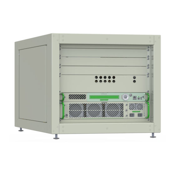
Page 23: Construction
E-Compact Medium Power 3. Construction The E-Compact family of medium power solid-state DTV transmitters provides maximum flexibility for site layout and installation. Transmitters are installed in custom designed 22” wide (19” panel opening) cabinets. Being available in two configurations depending on the output power: EC702MP ATSC Transmitter 170 W and EC704MP ATSC Transmistter 350 W. - Page 24 E-Compact Medium Power DESCRIPTION Cabinet 8RU 1U slot void Ethernet switch Main CM8001 control module Backup CM8001 Control Module PA702MP – Power amplifier (EC702MP) PA704MP – Power amplifier (EC704MP) MOD 40243 - EIA 1-5/8” low pass filter MOD 40215 – RF sample EIA 1+5/8” RF Spliter 1:2 MOD 40090A –...
- Page 25 E-Compact Medium Power DESCRIPTION Cabinet 8RU 1U slot void Ethernet switch Main CM8001 control module PA702MP – Power amplifier (EC702MP) PA704MP – Power amplifier (EC704MP) MOD 40243 - EIA 1-5/8” low pass filter MOD 40215 – RF sample EIA 1+5/8” AC mains protection unit Construction EC702MP / EC704MP SINGLE EXCITER...
-
Page 26: Footprint
E-Compact Medium Power 4. Footprint Footprint EC702MP / EC704MP DOUBLE EXCITER 26 | 106 SINGLE EXCITER... -
Page 27: Block Diagram
E-Compact Medium Power 5. Block Diagram TS IN Mai n ATSC Ex ci ter ANTENNA (NOT INCLUDED) 10dB B. FILTER Attenuator AC in RF OUT (NOT INCLUDED) TS IN Backup ATSC Exciter (NOT INCLUDED) 10dB Attenuator AC in B. FILTER RF OUT (NOT INCLUDED) Ethernet Switch... - Page 28 E-Compact Medium Power ANTENNA TS IN ATSC Exciter (NOT INCLUDED) B. FILTER Exciter AC in RF OUT Ethernet Switch AC in CM8001 Control Module RF IN MOD 40243 AC in EIA 1-5/8" Low Pass Filter RF OUT Before Filter Exciter PA702MP / PA704MP RF SAMPLE (+10dBm)
-
Page 29: Main Modules
E-Compact Medium Power 6. Main Modules 6.1. CM8001 Control Module (MOD GV 40056) The E-Compact series of transmitters utilize a dedicated 1RU controller chassis, CM8001. The controller chassis has several functions including: Access to exciter setup / monitoring AC mains power monitoring •... -
Page 30: Interfaces
E-Compact Medium Power 6.1.2. Interfaces Front Panel Rear Panel LCD Display (2 Lines x 40 Coluns) USB 2.0 Port Type B Jack Signaling LEDs USB 2.0 Port Type A Jack Power On Key Up Key (▲) AC Input Down Key (▼) NOT USED / NOT APPLY Left Key (◀) “Tuner IN”... -
Page 31: Control System Functional Description
E-Compact Medium Power 6.1.3. Control System Functional Description MAIN EXCITER (NOT INCLUDED) BACKUP EXCITER (NOT INCLUDED) RF: +1dBm RF: +1dBm Exciter Status Exciter Status COAXIAL RELAY MAIN CM8001 BACKUP CM8001 CONTROL MODULE CONTROL MODULE (OPTIONAL) Communication Control I/O PA702MP / PA704MP POWER AMPLIFIER +8Vcc from MCCB (NOT USED TO MEDIUM POWER SERIES) +15VCC - MCCB Source Monitor... -
Page 32: Control System Operation
E-Compact Medium Power 6.1.4. Control System Operation 6.1.4.1. Navigation The Control Module CM8001 has a system of configuration, measurements, alarms and remote management (TELESUPERVISION), that controls all the modules of the transmitter. The configuration of the transmitter might be done either by its front panel, of the transmitter or the web interface using a browser of your choice or SNMP. - Page 33 E-Compact Medium Power When navigating through the different functions (status and setup), take into consideration the keyboard symbols and the descriptions below (See 5.1.1 Interfaces): ▲ Moves the arrow UP to the next function shown on LCD screen ▶ Moves the arrow to the next RIGHT position ▼...
-
Page 34: System Structure
E-Compact Medium Power 6.1.4.2. System Structure The system consists of the Root Menu "Main Menu" that gives access to four categories of Menu: ⇨ Main Menu ⇨Setup Menu: Access to configure the equipment parameters. ⇨ Main Menu ⇨Measurements: Access to consult the parameters of the equipment. ⇨... -
Page 35: Main Menu ⇨ Measurements
E-Compact Medium Power Parameter Position Description / Functionality Power Setup 1100 Changes the output power of the Equipment. Automatic Level Control: On/Off Transmitter Setup 1200 Ctr Mode: Active / Standby Change the date, time and date format (dd/mm/yy or Time and Date Setup 1300 mm/dd/yy) Enable / Choose new password... - Page 36 E-Compact Medium Power The [2300] Drawers Measurements parameter allows to view the main status of all Power Amplifiers Drawers: DRAWERS IDENTIFICATIONS PA IDENTIFICATIONS PA IDENTIFICATIONS PA702MP - POWER AMPLIFIER PA704MP - POWER AMPLIFIER Top View Top View Power Amplifier Drawer Power Supply 1 Power Supply 2 1/3 Power Supply: Voltage measure of all Power Amplifier Drawers Sources...
- Page 37 E-Compact Medium Power 2/3 Current: Current measure (Amper) in all Power Amplifier Drawers Transistors and Drive (Eight Power Transistors and one Drive per Power Amplifier Drawer): Position Description / Functionality I1: [A] I2: [A] - Transistor 1 and Transistor 2 Current 2320 I3: [A] I4: [A]...
-
Page 38: Main Menu ⇨ System Alarms/Log
E-Compact Medium Power Parameter Position Description / Functionality +3,3V : OK - Check de +3,3Vcc Ctrl Module Power Supply +15V : OK - Check de +15Vcc Ctrl Module Power Supply Control Module 2400 Power Supply +5V : OK - Check de +5Vcc Ctrl Module Power Supply +28V : OK - Check de +28Vcc Ctrl Module Power Supply Drawers Communication Status (OK / Fail / -- “not present”) P01 / P02 / P03 / P04 –... -
Page 39: Equipment Alarms
Check the RS485 cable connections in the rear panel of the excitation Drawer Comm. drawer and power drawers. Check the internal interconnections of Failure connectors. Get in contact with Hitachi Kokusai Linear's technical support service. Check the power drawers for proper operation using the HyperTerminal. Drawers Alarms Failure in any of the Power Drawers. - Page 40 Reflected Power whole. Check the connections of the equipment to filter and filter the antenna. Get in contact with Hitachi Kokusai Linear's technical support service. Remote Ctrl Failure Indicates communication failure in the Remote Control Drawer.
-
Page 41: Power Amplifiers Drawers Alarms
E-Compact Medium Power POWER AMPLIFIERS DRAWERS ALARMS This list is directly related to the alarms that occur in the Power Drawers. When there is an alarm LED lit (see item 5.2.6 - Signaling Leds - Power Amplifier Module) the alarm detail is displayed when accessing the "System Alarms / Log"... - Page 42 E-Compact Medium Power ALARM ALARM DESCRIPTION Power Amplifier Drawer forward output power is greater than 1300Watts. Critical High Forward Power Default system action: Shutdown. Drawer reflected output power is greater than 184Watts. Critical High Reflected Power Default system action: Shutdown. Ambient air temperature used in the reflow of the equipment is greater than 48°C (118,4ºF).
- Page 43 E-Compact Medium Power ALARM ALARM DESCRIPTION VGS (Voltage Gate Source) of the indicated PA is less than 2/3 of the programmed VGS. PA__ Failure Default system action: Shutdown. No communication with the indicated PA. PA__ Comm Failure Gain in the driver is less than 30dB. Driver Low Gain Default system action: Notification Voltage in the driver is less than 5.0V of programmed.
- Page 44 E-Compact Medium Power ALARM ALARM DESCRIPTION AC Voltage at PSU is less than 170Vac PSU __ Critical Low AC Line Voltage Default system action: Shutdown Power at PSU indicate exceeds 1300Watts PSU __ Critical High Current Default system action: Shutdown Temperature at PSU is greater than 60°C (140ºF).
-
Page 45: Browser Alarms Status
E-Compact Medium Power BROWSER ALARMS STATUS Parameter Position Description / Functionality Current Alarms 3100 Show the list of currents Alarms in the Equipment. 01 Number of Alarm of Total Alarms 02 ▲ or ▼ to view the Alarms List When there is no alarm, it will display: “Alarm List Empy” Parameter Position Description / Functionality... -
Page 46: Main Menu ⇨ Remote Access
E-Compact Medium Power Indicates which Drawer/Module indication 02 Indicates “Current Alarms [3310] or “past Alarms [3320] 03 Number of Alarm of Total Alarms 04 Alarm List Press ▲ or ▼ to browse in the Alarm List. Parameter Position Description / Functionality Clear Alarm Log Show the list of past Alarms Select this option to clear all alarm logs. -
Page 47: Frontal Led Alarms
E-Compact Medium Power 6.1.5. Frontal Led Alarms CURRENT ALARM: When a fault occurs, the equipment will automatically take containment and protection actions (Power Off or Power Reduce) and signal by the "CURRENT ALARM" led on the front panel. These may be checked via the display in the menu: [3000] System Alarms / Log. -
Page 48: Pa704Mp / Pa702Mp Power Amplifier Module
E-Compact Medium Power 6.2. PA704MP / PA702MP Power Amplifier Module This is an air-cooled UHF power amplifier drawer composed of an RF block with until four power transistors that utilize Doherty's high efficiency technology. Each Drawer can provide up to 450 Watts RMS (ATSC 1.0) or up to 400 Watts RMS (ATSC 3.0) with efficiency between 34% and 41% depending on the operating channel. -
Page 49: Interfaces
Interfaces PA702MP / PA704MP E-Compact Medium Power POWER AMPLIFIERS FRONT / REAR VIEW 6.2.1. Interfaces DESCRIPTION Signaling LEDs USB Interface Removable front panel Fan Air Filter Power Source 1 (PS1) On/Off Power Source 1 (PS1) Slot for Redundant Power Source (Only PA702MP) AC Power input GND connector Front Panel –... -
Page 50: Specifications
E-Compact Medium Power 6.2.2. Specifications Specification Characteristic PA702MP PA704MP Frequency 470 to 806 MHz Range See PA702MP / PA704MP Channel Range Table Level 0.0 to 8.0 dBm (±1dB) Input Connector / SMA female / 50 Ohms Impedance Return Loss -20dB typical ( -18dB Max ) Frequency 470 to 806 MHz... -
Page 51: Power Amplifier Block Diagram
E-Compact Medium Power 6.2.3. Power Amplifier Block Diagram 470 ~ 806MHz PA702MP GAIN = +52dB ±4dB POUT: 215 W @ ATSC3.0 USB Comm POUT: 225 W @ ATSC1.0 USB Comm Control Module / Exciter Int erface Control Module / Exciter Communication –... - Page 52 E-Compact Medium Power CHANEL RANGE PA702MP DOHERTY COMBINER PA702MP COMBINER 1:1 14 ~ 17 HKL1001100 - MOD CIM 30238 470-494MHZ MP HKL1003777 - MOD 40176 SOM 1:1 470-570MHZ MP 18 ~ 21 HKL1001101 - MOD CIM 30239 494-518MHZ MP HKL1003777 - MOD 40176 SOM 1:1 470-570MHZ MP 22 ~ 24 HKL1001102 - MOD CIM 30240 518-534MHZ MP HKL1003777 - MOD 40176 SOM 1:1 470-570MHZ MP...
- Page 53 E-Compact Medium Power 470 ~ 806MHz PA704MP GAIN = +52dB ±4dB POUT: 400 W @ ATSC3.0 USB Comm POUT: 450 W @ ATSC1.0 USB Comm Control Module / Exciter Interface Control Module / Exciter Communication – Drawer Address Comm. – Drawer Address Alarms Led Alarms Led +5Vcc...
- Page 54 E-Compact Medium Power CHANEL RANGE PA704MP DOHERTY COMBINER 14 ~ 17 HKL1000524 - MOD CIM 30146 470-494MHZ MP 18 ~ 21 HKL1000525 - MOD CIM 30147 494-518MHZ MP 22 ~ 24 HKL1000526 - MOD CIM 30148 518-534MHZ MP 25 ~ 26 HKL1000527 - MOD CIM 30149 534-550MHZ MP 27 ~ 29 HKL1000528 - MOD CIM 30161 550-566MHZ MP...
-
Page 55: Signaling Leds
E-Compact Medium Power 6.2.4. Signaling LEDs Each Power Amplifier Drawer Features a LED bank that indicates the situation of its operation according to the color As shown below:: Green Normal operation. Orange Orange light indicates That a failure has occurred. Flashing Red light indicates an ongoing failure. -
Page 56: Communication Interface (Comm)
E-Compact Medium Power 6.2.5. Communication interface (COMM) COMM 6.2.6. 1200 Watts Powers Supplies The Power Amplifiers Drawers use two 1200 Watts plug-in power supplies. Each of the power supplies in the power amplifier converts 180-240VAC single-phase line voltage to 40-50VDC to power the RF pallets. - Page 57 E-Compact Medium Power Power Supply Replacement PA702MP / PA704MP 57 | 106...
-
Page 58: Power Supply 1200Watts - Mod 40241
E-Compact Medium Power 6.2.7. Power Supply 1200Watts – MOD 40241: AC/DC Converter - PFC DC/DC Converter AC Mains Input 180 ~240 VAC DC Input 350 ~400vdc AC Mains Frequency 50 ~ 60Hz Switching Frequency 50kHz Switching Frequency 100kHz 40 ~50vdc DC Output 375VDC DC Output... -
Page 59: Eia 1-5/8" Low Pass Filter
E-Compact Medium Power 6.3. EIA 1-5/8” low pass filter RF OUT RF IN The Low Pass Filter is installed between the Power Amplifier Drawer RF Output and the Mask Filter attenuating unwanted harmonic products so that they do not return as reflected wave to the PA. Low Pass Filter Frequency Range and Models: CHANNEL RANGE MODEL... -
Page 60: Mod 40215 Eia Rf Output Line With Sample Probe
E-Compact Medium Power 6.4. MOD 40215 EIA RF Output Line with Sample Probe The 4.5. EIA RF Output Line with Sample Probe is a passive coaxial RF sample installed in the Mask Filter RF output and has four independent RF outputs samples. It has two signal samples for use in the non-linear adjustment, a sample for the reflected power monitoring and a direct power monitoring sample. - Page 61 E-Compact Medium Power Use for Non-Linear Correction A – FWD Sample Forward Power Sample Connection: N Coupling: -52dB (MAX); -61dB (MIN) B – FWD Sample Impedance: 50Ω To monitor Reflected Power Output. Reflected Power Sample C – REF Sample Connection: N Coupling: -52dB (MAX);...
-
Page 62: Ac Mains Protection Unit
E-Compact Medium Power 6.5. AC Mains Protection Unit The AC Protection Unit is responsible for the AC Power distribution and Equipment AC Power protection. Characteristics: ⇨ Surge Protection Device (SPD). ⇨ Circuit Breaker. ⇨ AC Line Input. ⇨ AC Mains Internal distribution. ⇨... - Page 63 About AC MAINS TYPE, see Section 8 – Attachments, USA AC Mains Types for E- Compact Series. Never open the device: there is a risk of electric shock. If necessary, contact Hitachi Service. Before Connecting the Machine to the AC Mains, one must ensure that the grid Voltage meets the equipment’s settings.
-
Page 64: M208 Mains Protection Unit - 208Vac Wild Leg
E-Compact Medium Power 6.5.2. M208 Mains Protection Unit – 208VAC WILD LEG 1 Φ 208VAC Neutral Neutral (Grey) Phase (Red) Ground (yelow/green) Bipolar Circuit Breaker 25A 5SL1 225-7MB Sparkler F-MS 12 ST- TVS 260 VAC Varistor VAL-MS 230 ST - 275Vac GND / Neutral Input Connector GND / Neutral Protection Connector 64 | 106... -
Page 65: B240 Mains Protection Unit -Single Phase 240 Vac
E-Compact Medium Power 6.5.3. B240 Mains Protection Unit –SINGLE PHASE 240 VAC 2 Φ 240VAC Phase (Grey) Phase (Red) Ground (yelow/green) Bipolar Circuit Breaker 25A 5SL1 225-7MB Varistor VAL-MS 120 ST - 150Vac Varistor VAL-MS 120 ST - 150Vac GND / Neutral Input Connector GND / Neutral Protection Connector 65 | 106... -
Page 66: Changing Ac Mains
See 6.5.2 For Not Available cases, it is necessary to replace the complete AC Mains Module for the compatible electrical grid. Contact Hitachi Kokusai Linear Service. When replacing the AC Mains type, pay attention to circuit breakers, varistors and sparklers models for their characteristics. Each type of AC Mains uses different values of these protection components. -
Page 67: Exciter Interface
E-Compact Medium Power 6.6. Exciter Interface The transmitters of the E-Compact Medium Power family have a monitoring interface for external exciters to communicate with the CM8001 Control Module. There are two interfaces, one for the main driver and one for the backup: Control I/O In Parameters Status... -
Page 68: Section 4 - Installation
In such a case, please get in contact with Hitachi Kokusai Linear Equipamentos Eletrônicos S/A's Technical Support Department. -
Page 69: Fastening Of Cables, Antennas And Connectors
E-Compact Medium Power a) It feature of special insulator supports for descent of cordage of lightning rod, with a space of 1,5m maximum between them. b) There must be a lightning signaling system in every 20m along the tower. c) It must be painted with orange and white stripes in every 2m with a special paint that complies with local regulations. -
Page 70: Indoors Equipment Installation
E-Compact Medium Power Stacking antennas When using this system, the distance between them depends on the kinds of antenna used and the kind of stacking used. This must be studied thoroughly in order to obtain the best solution for each case. Cables and Connectors All cables must be carefully installed in order not to be twisted during the installation process. -
Page 71: Electric Installation Grounding
E-Compact Medium Power To determine the behavior of the soil capacity to drain the currents, its resistivity has to be measured. For an adequate protection this value should not exceed 5 , being zero the ideal value Generally, the grounding method used for TV retransmitters is a system with a single vertical electrode made with copper measuring 2.5 meters or more. -
Page 72: Equipment Assembly
E-Compact Medium Power 4. Equipment Assembly Only trained and trained personnel should conduct physical assembly on site. Observe the requirements described in this manual in Sections 1 (Care, Warranty and Service) and Section 2 (Minimum Installation Requirements). The following precautions must be taken when positioning the transmitter at the installation site: (1) The air intake (front) and the air outlet (rear) must be completely unobstructed. - Page 73 E-Compact Medium Power (5) Remove the cabinet rear and side housings to facilitate equipment mount. Cabinet 8RU mount: Unlock When finalizing the assembly and the Equipment is operating normally, close the cabinet whit the housings. 73 | 106...
- Page 74 E-Compact Medium Power Double Exciter Single Exciter DESCRIPTION Cabinet 8RU Main Exciter (NOT INCLUDED) Backup Exciter (NOT INCLUDED) Screw in all rack drawers: Ethernet switch Main CM8001 control module Backup CM8001 Control Module PA702MP – Power amplifier (EC702MP) PA704MP – Power amplifier (EC704MP) EC702MP / EC704MP CABINET DRAWERS MOUNT 74 | 106...
- Page 75 E-Compact Medium Power Screw in the filter on the cabinet top. DESCRIPTION MOD 40243 - EIA 1-5/8” low pass filter Fix the filter hanger clamp on the cabinet rod. EC702MP / EC704MP LOW PASS FILTER INSTAL 75 | 106...
- Page 76 E-Compact Medium Power AC IN Mai n E xciter AC IN B ackup Exciter Use 10dB attenuator MOD 400 90A Flayback 15/8V 25W to connect Power Amplifier RF Sample to Feedback Before AC IN E the rnet Filter Exciter. Switch CM800 1 RF Spl iter 1:2 Main Control Mod ule...
- Page 77 E-Compact Medium Power AC IN E xciter Use 10dB attenuator to connect Power Amplifier RF Sample to Feedback Before Filter Exciter. AC IN E the rnet Switch CM800 1 Control Mo dule TUNER IN RF OU T AC IN CONTROL I/O RF SAMPLE RF IN COMM.
- Page 78 E-Compact Medium Power ANTENNA MOD 40215 RF Sample EIA 1-5/8" Mask Filter (NOT INCLUDED) MOD 40243 Low Pass Filter Connect the Power Amplifier RF OUT to the MOD 40243 Low Pass Filter EC702MP / EC704MP RF OUTPUT CONNECTIONS 78 | 106...
- Page 79 E-Compact Medium Power GROUND GROUNDING GRID Main Exciter Connect all drawers on cabinet grounding grid GROUND Backup Exciter CM800 1 Main Control Mod ule RF OU T CM800 1 Backup Co ntr ol Mod ule COMM. PA702MP / PA704MP – Power Amplifier SCREW GROUNDING CABINET GROUND...
- Page 80 E-Compact Medium Power AUXILIARY AC CONNECTOR MAX: 250VAC – 10A USE PROTECTIVE DEVICES (Circuit Breakers / Fuses) AC OUT PHASE PHASE AC MAINS INPUT AC MAINS INPUT 180 to 254VAC 43 to 63 Hz AC MAINS EC702MP / EC704MP AC MAINS CONNECTIONS AC INPUT AC MAINS M208...
-
Page 81: Ethernet Connections
E-Compact Medium Power 4.2. Ethernet Connections Connect between the switch module and Telesupervision Module, Exciter 1, Exciter 2, Control Module 1, Control Module 2. Use Cat5 Cable whit RJ45 Connector. Main Exciter (Not Included) Backup Exciter (Not Included) Switch Module Main Control Module Drawer –... -
Page 82: Ac Electrical Line Connection
E-Compact Medium Power 4.4. AC Electrical Line Connection Prior to energizing the transmitter, one must make sure that the circuit breaker and the power switch (ON / OFF) are switched off or disabled.. 4.4.1. Electrical line connection (EC70xMP) The Electrical Line is connected to the AC Unit: Before Connecting the Machine to the AC Mains, one must ensure that the grid Voltage meets the equipment’s settings. -
Page 83: Section 5 - Initial Activation
E-Compact Medium Power Section 5 - Initial Activation 1. Overview. After finishing the installation, the equipment is ready to be activated. It is important to observe that the transmitter is configured at the factory with the parameters that were supplied by the customer at the time he made the purchase, such as the channel output, power, MER, etc. -
Page 84: Activation
E-Compact Medium Power 2. Activation. The steps of this activation must be followed to avoid damage to the equipment. Before Turn-On, Check if all on/off key Drawers it’s “off” Trigger the circuit breaker on (01) Check if both the Exciter (Main and Backup) are configured for the correct channel, the same as the Mask Filter and the Antenna. - Page 85 E-Compact Medium Power Set the Programmed Power in Main Module Control CM8001 to 10% of the total power of the equipment Display Interface >Measurements [2000] > Power [2100] > Programmed Power [1/3] Check: Alarms Occurrences: >System Alarms/Log [3000]> Current Alarms [3100] •...
-
Page 86: Main Operations
E-Compact Medium Power Check if there is any abnormal or differential heating, in the connection joints between the transmitter, filter, antenna and adder’s imbalance load. If there is any abnormal warming in an isolated way, this may indicate some flaw or imperfection in that connection. This must be checked before further increasing the transmitter power. -
Page 87: Protections
E-Compact Medium Power 5. Protections 5.1. Reflected Power If the incidence of reflected power at the transmitter due to any external or internal factor occurs, refer to the measurement screen (MEASUREMENTS [2000]) by browsing the software’s navigation Menu, according to instructions given in the Operation Section of the Digital Control System. If the value of the reflected power exceeds the value of 2%* of rated power, the control will immediately signal Through the Current Alarm LED, and this will trigger the routine protection against reflected power. -
Page 88: Transmitter Operating Temperature Configuration
E-Compact Medium Power 5.4. Transmitter Operating Temperature Configuration The transmitter’s operating temperature is measured on the power modules’ transistors, and is configurable between 50°C e 60°C. Configuration is done through the front panel Menu: Setup Menu “PA Temperature Control” (Setup Menu [1M00]). This configuration varies according to room temperature and the transmitter’s efficiency, and it is necessary to optimize operating temperature and equipment’s lifespan. -
Page 89: Section 6 - Web Interface
If the multicast stream is on the same network that will be used for WEB interface access, a Managed PoE Ethernet Switch must be used to isolate this access from the multicast stream. For more information contact Hitachi Technical Assistance. 89 | 106... -
Page 90: Configuring The System
E-Compact Medium Power 2. Configuring the System The WEB interface can be accessed through the Main or the Backup Control ModuleCM8001 via a web browser through one of the IP addresses configured in the Control Module itself. For navigation, you must use a recent internet browser, updated in its latest version. To control the device through the web interface, we recommend Chrome or Firefox Browsers,. -
Page 91: Startup
E-Compact Medium Power 3.2. Startup The equipment management interface is subdivided into six (6) tabs as shown below: ⇨ Alarms – Verification of existing alarms (System Alarms). ⇨ Setup – Power Setup, import and export files. ⇨ Measurements – Verification of system measures. ⇨... -
Page 92: Alarm Log
E-Compact Medium Power 3.3.2. Alarm Log View the list of alarms that ran during the Machine operating period. The symbol ‘[!]’ before log indicates the date and time when the alarm occurred are recorded. The symbol ‘[#]’ before the log indicates the date and time when the alarm stopped to happen are recorded. 92 | 106... -
Page 93: Download Alarm Log
E-Compact Medium Power 3.3.3. Download Alarm Log Through this screen you can save the list of alarms generated for further analysis. To save the file, click the right button Download. 93 | 106... -
Page 94: Setup
E-Compact Medium Power 3.4. Setup To set the power level of the transmitter, it is necessary to access the item “Setup” starting from the home screen. 3.4.1. Power Setup Changes the output power of the Equipment. 94 | 106... -
Page 95: Transmitter
E-Compact Medium Power 3.4.2. Transmitter This screen allows you to restart the transmitter. 3.4.3. Exciter CM8001 is a control Module, the Exciter is installed by the customer. One should always check the third party exciter’s manual for remote access. This menu has no functionality. 3.4.4. -
Page 96: Measurements
E-Compact Medium Power 3.5. Measurements This screen displays information: System identification, standard, channel and equipment, model, software versions and hardware, programmed Power, direct and reflected; ALC voltage; Status of the voltages source of digital exciter; communications status and status of the voltages of system. To access it, just select the Measurements item. -
Page 97: Power
E-Compact Medium Power 3.6. Power 3.6.1. Measurements This screen allows one to view power drawer information. To verify this information, select Power on the home screen. 97 | 106... -
Page 98: Cur. Alarms
E-Compact Medium Power 3.6.2. Cur. Alarms Visualize the alarms that are occurring of the Power Amplifiers Drawer. The alarm significance table is found in Section 5.1.4.2 - System Structure of Section 3. 3.6.3. Past Alarms View the list of alarms that ran during the Power Amplifier Drawer operating period. 98 | 106... -
Page 99: Remote
E-Compact Medium Power 3.7. Remote This screen allows to read system information and configure the machine for operation in remote mode. Through this configuration, it can be monitored all parameters and measures as well as from the front panel through the WEB server. To do this it is necessary to configure the IP / Mask / Gateway selecting the Remote option. -
Page 100: User
E-Compact Medium Power 3.8. User Through the User interface is possible to change the password. To access it, select the User item. Current password: Field for entering the current password system. New Password: It allows the user to enter the new password. Confirm New Password: It allows the user to type the new password for confirmation. -
Page 101: Section 7 - Preventive Maintenance
E-Compact Medium Power Section 7 – Preventive Maintenance 1. Overview This section is dedicated to the necessary procedures for proper preventive, periodic and corrective maintenance in order to guarantee an TV transmitter that works properly and for a longer period of time. Only trained and authorized people should be allowed to open the transmitter. -
Page 102: Visual Inspection
E-Compact Medium Power (4) If you can’t use an air blower, use a brush with soft bristles to avoid scratching the equipment. (5) When you are done cleaning the equipment, put the side covers back in place, redo all RF and power connections and turn the equipment on. -
Page 103: Section 8 - Attachments
E-Compact Medium Power Section 8 - Attachments 1. USA AC Mains Types for E-Compact Series Common Electrical Services AC Mains Single Phase 240Vac (B240) AC Input PHASE A NEUTRAL (Not Used) PHASE B Chassis GROUND 103 | 106... - Page 104 E-Compact Medium Power AC Mains Wye Three-Phase 208Vac (T208) AC Input PHASE A PHASE B Chassis NEUTRAL (Not Used) PHASE C GROUND Uncommon Electrical Services AC Mains Delta Three-Phase 240Vac (T240) AC Input PHASE B Chassis PHASE A NEUTRAL (Not Used) PHASE C GROUND 104 | 106...
- Page 105 E-Compact Medium Power AC Mains Single Phase 208Vac Wild Leg (M208) - using Delta Three-Phase 240Vac PHASE B AC Input (Wild Leg) Chassis PHASE A (Not Used) NEUTRAL PHASE C (Not Used) GROUND AC Mains Wye Three-Phase 380Vac (T380) AC Input PHASE A PHASE B Chassis...
- Page 106 E-Compact Medium Power 106 | 106...