Advertisement
Available languages
Available languages
Quick Links
Time Code
Input/Output Board
取扱説明書
2
ページ
Operating Instructions
Mode d'emploi
Bedienungsanleitung
Istruzioni per l'uso
お買い上げいただきありがとうございます。
電気製品は、安全のための注意事項を守らないと、火
警告
災や人身事故になることがあります。
• ご使用にあたっては、デジタルビデオカセットレコーダー本体に付
属の取扱説明書の「安全のために」と「
お読みください。お読みになったあとは、いつでも見られるところ
に必ず保管してください。
• 本基板の取り付けは、必ずお買い上げ店またはソニーのサービス窓
口にご依頼ください。
DSBK-130/130P
© 1996 by Sony Corporation
Page 9
Page 15
Seite 21
Pagina 27
3-858-534-04(1)
警告」 、 「
注意」をよく
J
EN
F
D
I
Advertisement

Related Manuals for Sony DSBK-130

Summary of Contents for Sony DSBK-130
- Page 1 取扱説明書 ページ Operating Instructions Page 9 Mode d’emploi Page 15 Bedienungsanleitung Seite 21 Istruzioni per l’uso Pagina 27 お買い上げいただきありがとうございます。 電気製品は、安全のための注意事項を守らないと、火 警告 災や人身事故になることがあります。 • ご使用にあたっては、デジタルビデオカセットレコーダー本体に付 属の取扱説明書の「安全のために」と「 警告」 、 「 注意」をよく お読みください。お読みになったあとは、いつでも見られるところ に必ず保管してください。 • 本基板の取り付けは、必ずお買い上げ店またはソニーのサービス窓 口にご依頼ください。 DSBK-130/130P © 1996 by Sony Corporation...
- Page 2 日本語 警告表示の意味 取扱説明書および製品では、次のような表示をしています。表示の内容をよ く理解してから本文をお読みください。 警告 この表示の注意事項を守らないと、火災や感電などにより死亡や大けがなど 人身事故につながることがあります。...
- Page 3 目次 取り扱い説明 概要 ..............設置説明 警告 ............... 取り付け ............. 日 本 語...
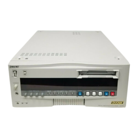
- Page 4 概要 取り付け タイ ムコー ドイ ンプッ ト/アウ ト プッ ト ボー ドDSBK-130は、 DSR-85/80/60な どのソニーデジタルビデオカセッ ト レコーダー/プレーヤー(以下 「VTR」 と 言います) のためのオプシ ョ ン基板です。 本基板をVTRに取り付ける こ と によ り、 SMPTEフ ォーマッ ト に準拠したタイ ムコー ド (LTC) 信号の入出力 が可能になり ます。 本基板を取り付けたあとの接続や入出力信号の仕様については、 VTRの 取扱説明書をご覧く ださい。...
- Page 5 取り付け VTRの天板を取り外し、 次に基板押さ え (1) および (2) を取り外す。 基板押さえ 天板 ネジ ネジ ネジ 基板押さえ DSR-85 の場合は SY-220 基板を、 DSR-80/60 の場合は SY-241 基板 を取り外す。 それぞれのSY基板は、 VTRの前面から見て下記の位置のスロ ッ ト に 装着されています。 スロ ッ ト フ レームの刻印 ←SY で確認してく ださ い。 DSR-85 の SY-220 基板:一番右のスロ ッ ト DSR-80 の...
- Page 6 取り付け DSBK-130 基板のコネクターを、 SY-220または SY-241 基板のコネク ターにしっかり と差し込む。 DSBK-130 基板 SY-220 基板または の方向から見て、 SY-241 基板 コネクター間にすき間 ができないように完全 に結合させる。 すき間がない。 すき間がある。 DSBK-130に付属のネジ 2 本で、 DSBK-130 基板と SY-220または SY-241 基板を互いに固定する。 SY-220 SY-241 または 基板の 金属カバー 金属カバーに開いている穴 の中を見て、周囲に白い斜 線が見えるネジ穴を選ぶ。 DSBK-130...
- Page 7 SY-220または SY-241 基板を、 VTR の基板スロ ッ ト に戻す。 両端のレバーを倒し、両手で確実に 奥まで押し込む。 手順 で取り外した基板押さ え (1) および (2)を取り付け、 次にVTR の天板を取り付ける。 基板押さ え (1) には 7 対のツメがあ り ます。 これらのツメが対応の基 板の上縁をはさむよう に取り付けてく ださい。 基板押さえ ネジ ネジ ネジ 基板押さえ...
- Page 9 English For the customers in the USA This equipment has been tested and found to comply with the limits for a Class A digital device, pursuant to Part 15 of the FCC Rules. These limits are designed to provide reasonable protection against harmful interference when the equipment is operated in a commercial environment.
- Page 10 Overview The DSBK-130/130P Time Code Input/Output Board is an option for the Sony DSR-85/85P/80/80P/60/60P or other digital videocassette recorder/player (hereafter referred to as “VCR”). When this option is fitted in the VCR, it becomes possible to input and output an SMPTE- or EBU-format analog time code (LTC) signal.
-
Page 11: Installation
Installation Remove the top cover from the VCR, then remove the board retainers (1) and (2). Board retainer (1) Top cover Screw Screw Screw Installing the Driver Software Board retainer (2) Remove the SY-220 board from the DSR-85/85P VCR, or remove the SY-241 board from the DSR-80/80P/60/60P VCR. - Page 12 Installation Plug the connector of the DSBK-130/130P board firmly into the connector on the SY-220/241 board. Push the connector completely in, so that there is no gap DSBK-130/130P board between the two connectors as seen SY-220/241 along the direction of board arrow (A).
- Page 13 Return the SY-220/241 board to the slot in the VCR. Push down the levers at both ends, and with both hands press the board firmly into position. Reattach the board retainers (1) and (2) removed in step 1, then the top cover of the VCR. The board retainer (1) has seven pairs of tongues.
- Page 15 Français Pour les utilisateurs au Canada Cet appareil numérique de la classe A est conforme à la norme NMB-003 du Canada. Sommaire Aperçu ................16 Installation ..............17...
- Page 16 Aperçu La carte d’entrée/sortie de temps codé DSBK-130/130P est une option destinée au DSR-85/85P/80/80P/60/60P ou à tout autre magnétoscope enregistreur/lecteur numérique Sony (appelé par la suite “magnétoscope”). Son insertion dans le magnétoscope permet l’entrée et la sortie de signaux de temps codé...
- Page 17 Installation Retirer le cache supérieur du magnétoscope, puis les retenues de carte (1) et (2). Cache Retenue de carte (1) supérieur Magnétoscope Retenue de carte (2) Retirer la carte SY-220 du magnétoscope DSR-85/85P, ou la carte SY-241 du magnétoscope DSR-80/80P/60/60P. Vu de l’avant du magnétoscope, la carte SY-220/241 se trouve dans le logement indiqué...
- Page 18 Carte SY-220/241 (A). Dans ce sens Pas dans ce sens Avec les deux vis fournies avec la carte DSBK-130/130P, fixer la carte DSKB-130/130P à la carte SY-220/241. Couvercle métallique de la carte SY-220/241 Regarder dans les trous du couvercle métallique pour...
- Page 19 Remettre la carte SY-220/241 dans le logement du magnétoscope. Pousser les manettes des deux extrémités vers le bas, puis des deux mains, presser fermement la carte en place. Réattacher les retenues de carte (1) et (2) déposées à l’étape 1, puis le cache supérieur du magnétoscope. La retenue de carte (1) est dotée de sept paires de lames de contact.
- Page 21 Deutsch Für Kunden in Deutschland Dieses Produkt kann im kommerziellen und in begrenztem Maße auch im industriellen Bereich eingesetzt werden. Dies ist eine Einrichtung, welche die Funk-Entstörung nach Klasse B besitzt. Inhaltsverzeichnis Kurzbeschreibung ............22 Installation ..............23...
- Page 22 Die Time Code Input/Output Board DSBK-130P ist eine optionale Leiterplatte für den Einbau in einen DSR-85P/80P/ 60P oder einen anderen digitalen Videorecorder/Player von Sony. Die Installation dieser Leiterplatte ermöglicht die Ein- und Ausgabe von analogen Zeitcodesignalen (LTC) im EBU- Format.
- Page 23 Installation Entfernen Sie die obere Abdeckung vom Videorecorder, und entfernen Sie die Leiterplattenhalterungen (1) und (2). Leiterplattenhalterung (1) Abdeckung Schraube Schraube Schraube Videorecorder Leiterplattenhalterung (2) Entfernen Sie die Leiterplatte aus dem DSR-85P bzw.die Leiterplatte SY-241 aus dem DSR-80P/60P. Von der Frontseite des Videorecorders/Players betrachtet sitzt die Leiterplatte SY-220/241 je nach Modell in dem nachfolgend aufgeführten Steckschlitzen.
- Page 24 Installation Stecken Sie die Leiterplatte DSBK-130P fest auf die Leiterplatte SY-220/241. Für festen Steckanschluß sorgen, so daß bei DSBK-130P Leiterplatte Betrachtung in Leiterplatte Pfeilrichtung (A) kein SY-220/241 Zwischenraum verbleibt. Richtig: Falsch: Sichern Sie die DSBK-130P mit den zwei mitgelieferten Schrauben an der SY-220/241 festschrauben. Metallabdeckung der SY-220/241 Die weiß...
- Page 25 Stecken Sie die Leiterplatte SY-220/241 wieder in ihren Steckschlitz im Videorecorder ein. Die Hebel nach unten drücken, und die Leiterplatte fest eindrücken. Bringen Sie die in Schritt 1 entfernten Leiterplattenhalterungen (1) und (2) wieder an, und schließen Sie wieder die Abdeckung des Videorecorder. Die Leiterplattenhalterung (1) verfügt über sieben Greiferpaare.
- Page 27 Italiano Indice Presentazione ..............28 Installazione ..............29...
- Page 28 Presentazione La scheda di ingresso/uscita codici temporali DSBK-130P è un accessorio opzionale per il DSR-85P/80P/60P Sony e altri videoregistratori/videoriproduttori a videocassette digitali (d’ora in poi citati come “videoregistratore”). Quando questa scheda opzionale è installata nel videoregistratore, diventa possibile immettere ed emettere segnali analogici di codice temporale (LTC) nel formato EBU.
-
Page 29: Installazione
Installazione Rimuovere il coperchio superiore del videoregistratore e quindi rimuovere i fermi delle schede (1) e (2). Fermo delle schede (1) Coperchio superiore Vite Vite Vite Installing the Driver Software Videoregistratore Fermo delle schede (2) Rimuovere la scheda SY-220 dal videoregistratore DSR- 85P, o rimuovere la scheda SY-241 dal videoregistratore DSR-80P/60P. - Page 30 Installazione Inserire il connettore della scheda DSBK-130P saldamente nel connettore sulla scheda SY-220/241. Inserire il connettore fino in fondo, in modo che non ci sia alcuno Scheda DSBK-130P spazio fra i due connettori guardando Scheda SY-220/ lungo la direzione della freccia (A). Così...
- Page 31 Reinserire la scheda SY-220/241 nella fessura sul videoregistratore. Abbassare le levette ad entrambe le estremità e con ambedue le mani premere la scheda in modo da fissarla saldamente in posizione. Riapplicare i fermi delle schede (1) e (2) rimossi al punto 1 e quindi il coperchio superiore del videoregistratore.
- Page 32 お問い合わせは 「ソニー業務用製品ご相談窓口のご案内」 にある窓口へ ソニー株式会社 〒141-0001 東京都品川区北品川6-7-35 ソニーマーケティング株式会社 情報システム営業本部 〒108-0074 東京都港区高輪4-10-18 Printed in Japan...