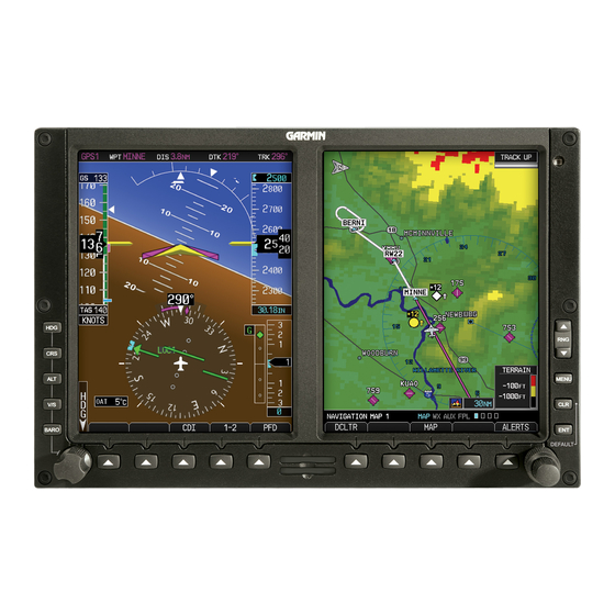
Garmin G500 Instructions Manual
Hide thumbs
Also See for G500:
- Pilot's manual (410 pages) ,
- Instructions manual (334 pages) ,
- Reference manual (104 pages)
Table of Contents
Advertisement
Instructions for Continued Airworthiness
Reg. No.____________
Rev.
Date
E
12/23/09
F
12/16/10
G
03/21/11
H
08/31/11
J
10/12/12
K
09/30/13
L
03/18/15
G500/G600 PFD/MFD System
as installed in
_____________________________
(Make and Model Airplane)
Dwg. Number:
190-00601-00 Rev. L
Garmin International, Inc.
1200 E. 151st Street
Olathe, Kansas 66062 USA
Record of Revision
Update referenced publications and revision procedures
Updated referenced publications. Clarified periodic maintenance
instructions. Added new special inspection requirements.
Update referenced IM. Specify overbraid, bonding strap, foil, corrosion
inspections; periodic bonding test. Clarify TVS test. Foil check annual.
Include GDC 74( ). TVS replace required after lightning.
Remove "FAA Approved" language. Update IM rev. Add additional
instructions for Mid-Continent standby attitude indicator installations.
Added GAD 43e. Removed reference to Pilot's Guide. Revised lightning
strike inspection.
Added RVSM support for TBM700(850).
Added support for G500 part numbers.
S/N_______________
Description of Change
Advertisement
Table of Contents

Summary of Contents for Garmin G500
- Page 1 Remove “FAA Approved” language. Update IM rev. Add additional 08/31/11 instructions for Mid-Continent standby attitude indicator installations. Added GAD 43e. Removed reference to Pilot’s Guide. Revised lightning 10/12/12 strike inspection. 09/30/13 Added RVSM support for TBM700(850). 03/18/15 Added support for G500 part numbers.
-
Page 2: Table Of Contents
2.17 Implementation and Record Keeping ..............11 3. APPENDIX A ......................... 12 System ........................12 LRU Locations ...................... 12 Wire Routing – Single-Engine ................13 Wire Routing – Twin-Engine ................. 14 G500/G600 PFD/MFD System 190-00601-00 Rev. L Instructions for Continued Airworthiness Page 2 of 14... -
Page 4: Introduction
2.1 Introduction Content, Scope, Purpose and Arrangement: This document identifies the Instructions for Continued Airworthiness for the modification of the aircraft by installation of the Garmin G500/G600 PFD/MFD System. Applicability: Applies to aircraft altered by installation of the Garmin G500/G600 PFD/MFD System. -
Page 5: Description Of Alteration
A and B (i.e. PFD 1A and PFD 1B). The GDU 620 has a PFD and MFD display and front panel controls for performing all G500/G600 normal and configuration operations. Knobs at the lower left and right corners are used for selecting and entering data on each screen. -
Page 6: Servicing Information
LRU. The electro-mechanical and electronic standby indicator (if installed) may have a TVS located at the indicator and/or at the power bus. See G500/G600 AML STC Installation Manual Table K-2 to help locate TVS installations. These components must be tested every 24 calendar months in accordance with section 8.3.1 of the G500/G600 AML STC Installation Manual. - Page 7 2.5.2 Aluminum Foil Tape (non-metallic aircraft only) Any aluminum foil tape used in the G500/G600 installation (see section 3.1 of this document) must be inspected every 12 calendar months in accordance with section 8.3.2 of the G500/G600 AML STC Installation Manual.
- Page 8 Otherwise maintenance of the Mid-Continent Instruments attitude indicator is ‘on condition’ only. 2.5.10 Electrical Bonding Test G500/G600 LRU electrical bonding must be tested every 2000 flight hours or ten (10) years, whichever is first. During the test, any cables normally attached to the LRU must be disconnected from the LRU. If measured resistance is greater than applicable values in the following table, bonding must be improved to meet applicable requirements for a new installation in accordance with section 3.8 of the G500/G600...
-
Page 9: Troubleshooting Information
GAD 43e Adapter Replacement If the GAD 43e is used with an analog navigation receiver, the GAD 43e calibration specified in 5.5.11.3 of the G500/G600 AML STC Installation Manual must be performed whenever the GAD 43e and/or the analog navigation receiver is replaced. -
Page 10: Diagrams
Aircraft specific LRU locations and wire routing diagram are recorded during installation using the forms in Appendix A of this document. Refer to the G500/G600 AML STC Installation Manual (listed under reference documentation in Section 2.1 of this document) for drawings applicable to this installation and for instructions to complete the forms in Appendix A. -
Page 11: Additional Instructions
The system does not require overhaul at a specific time period. Power on self-test and continuous BIT will monitor the health of the G500/G600 system. If any LRU indicates an internal failure, the unit may be removed and replaced. See the troubleshooting section contained in the G500/G600 AML STC Installation Manual, listed under reference documentation in paragraph 2.1 of this document. -
Page 12: System
3.1 System System Installed Single Dual G500 Single Dual G600 3.2 LRU Locations The following table describes the locations of the G500/G600 LRUs: Aluminum included in foil tape Description of Location this used for installation? grounding? ... -
Page 13: Wire Routing - Single-Engine
3.3 Wire Routing – Single-Engine The following diagram depicts the wire routing for the G500/G600 LRUs throughout the aircraft structure for a single-engine aircraft: G500/G600 PFD/MFD System 190-00601-00 Rev. L Instructions for Continued Airworthiness Page 13 of 14... -
Page 14: Wire Routing - Twin-Engine
3.4 Wire Routing – Twin-Engine The following diagram depicts the wire routing for the G500/G600 LRUs throughout the aircraft structure for a twin-engine aircraft: G500/G600 PFD/MFD System 190-00601-00 Rev. L Instructions for Continued Airworthiness Page 14 of 14...


