Table of Contents
Advertisement
Quick Links
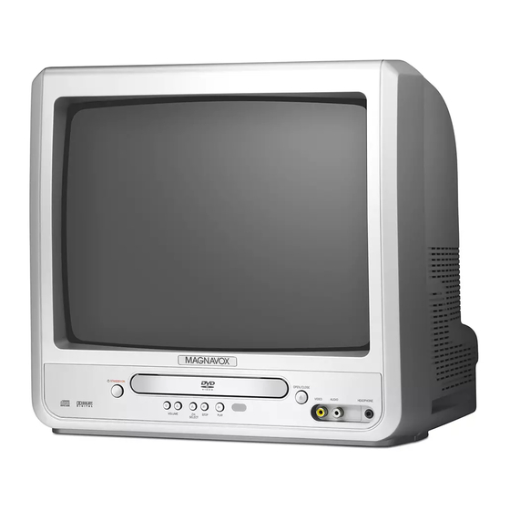
Color TV with Built-In DVD Player
Color TV with Built-In DVD Player
Service
Service
Service
Service
Service
Service
Service Manual
Service Manual
Contents
Contents
Chapter
Chapter
Adjustment Procedures
Adjustment Procedures
Schematic Diagrams and CBA's
Schematic Diagrams and CBA's
Exploded Views
Exploded Views
Mechanical and Electrical Parts Lists
Mechanical and Electrical Parts Lists
c Copyright 2006 Philips Consumer Electronics B.V. Eindhoven, The Netherlands.
c Copyright 2006 Philips Consumer Electronics B.V. Eindhoven, The Netherlands.
All rights reserved. No part of this publication may be reproduced, stored in a retrieval
All rights reserved. No part of this publication may be reproduced, stored in a retrieval
system or transmitted, in any form or by any means, electronic, mechanical, photocopying,
system or transmitted, in any form or by any means, electronic, mechanical, photocopying,
or otherwise without the prior permission of Philips.
or otherwise without the prior permission of Philips.
Published by FU-KC 0613 Service AV Systems
Published by FU-KC 0612 Service AV Systems
All manuals and user guides at all-guides.com
Survey of versions:
Survey of versions:
/37
/37
NTSC
NTSC
Printed in The Netherlands
Printed in The Netherlands
13MC3206/
20MC4206/
CLASS 1 LASER PRODUCT
CLASS 1 LASER PRODUCT
KLASSE 1 LASER PRODUKT
KLASSE 1 LASER PRODUKT
KLASS 1 LASER APPARAT
KLASS 1 LASER APPARAT
CLASSE 1 PRODUIT LASER
CLASSE 1 PRODUIT LASER
Subject to modification
Subject to modification
37
37
EN 3139 785 31820
EN 3139 785 31830
Advertisement
Table of Contents

Related Manuals for Philips 13MC3206/37


Summary of Contents for Philips 13MC3206/37
- Page 1 Mechanical and Electrical Parts Lists Mechanical and Electrical Parts Lists c Copyright 2006 Philips Consumer Electronics B.V. Eindhoven, The Netherlands. c Copyright 2006 Philips Consumer Electronics B.V. Eindhoven, The Netherlands. All rights reserved. No part of this publication may be reproduced, stored in a retrieval All rights reserved.
-
Page 2: Table Of Contents
All manuals and user guides at all-guides.com TABLE OF CONTENTS LASER BEAM SAFETY PRECAUTIONS ........... . 1-1-1 IMPORTANT SAFETY PRECAUTIONS. -
Page 3: Laser Beam Safety Precautions
All manuals and user guides at all-guides.com LASER BEAM SAFETY PRECAUTIONS This DVD player uses a pickup that emits a laser beam. Do not look directly at the laser beam coming from the pickup or allow it to strike against your skin. -
Page 4: Important Safety Precautions
All manuals and user guides at all-guides.com IMPORTANT SAFETY PRECAUTIONS Prior to shipment from the factory, our products are strictly inspected for recognized product safety and electrical codes of the countries in which they are to be sold. However, in order to maintain such compliance, it is equally important to implement the following precautions when a set is being serviced. - Page 5 All manuals and user guides at all-guides.com may be called “horizontal disable” or “hold regardless of the AC plug polarity. This chassis down.”) Read and apply the high voltage limits can be safety-serviced only with an isolation and, if the chassis is so equipped, the X- transformer inserted in the power line between radiation protection circuit specifications given the receiver and the AC power source, for both...
- Page 6 All manuals and user guides at all-guides.com Precautions during Servicing A. Parts identified by the # symbol are critical for safety. Replace only with part number specified. B. In addition to safety, other parts and assemblies are specified for conformance with regulations applying to spurious radiation.
- Page 7 All manuals and user guides at all-guides.com Safety Check after Servicing Examine the area surrounding the repaired location for damage or deterioration. Observe that screws, parts and wires have been returned to original positions. Afterwards, perform the following tests and confirm the specified values in order to verify compliance with safety standards.
-
Page 8: Standard Notes For Servicing
Due to lead-free technology some rules have to be respected by the workshop during a repair: Pin 1 • Use only lead-free solder alloy Philips SAC305 with order code 0622 149 00106. If lead-free solder- paste is required, please contact the manufacturer Instructions for Connectors of your solder-equipment. - Page 9 All manuals and user guides at all-guides.com • Mix of lead-free solder alloy / parts with leaded How to Remove / Install Flat Pack-IC solder alloy / parts is possible but PHILIPS recommends strongly to avoid mixed solder alloy 1. Removal types (leaded and lead-free).
- Page 10 All manuals and user guides at all-guides.com With Soldering Iron: With Iron Wire: 1. Using desoldering braid, remove the solder from 1. Using desoldering braid, remove the solder from all pins of the flat pack-IC. When you use solder all pins of the flat pack-IC. When you use solder flux which is applied to all pins of the flat pack-IC, flux which is applied to all pins of the flat pack-IC, you can remove it easily.
- Page 11 All manuals and user guides at all-guides.com 2. Installation Instructions for Handling Semi- conductors 1. Using desoldering braid, remove the solder from the foil of each pin of the flat pack-IC on the CBA Electrostatic breakdown of the semi-conductors may so you can install a replacement flat pack-IC more occur due to a potential difference caused by easily.
-
Page 12: Operating Controls And Functions
All manuals and user guides at all-guides.com OPERATING CONTROLS AND FUNCTIONS 1-4-1 T8201IB... - Page 13 All manuals and user guides at all-guides.com 1-4-2 T8201IB...
- Page 14 All manuals and user guides at all-guides.com 1-4-3 T8201IB...
- Page 15 All manuals and user guides at all-guides.com 1-4-4 T8201IB...
-
Page 16: Cabinet Disassembly Instructions
All manuals and user guides at all-guides.com CABINET DISASSEMBLY INSTRUCTIONS 1. Disassembly Flowchart desoldered. S=Screw, P=Spring, L=Locking Tab, CN=Connec- This flowchart indicates the disassembly steps for the tor, *=Unhook, Unlock, Release, Unplug, or Desol- cabinet parts, and the CBA in order to gain access to item(s) to be serviced. - Page 17 All manuals and user guides at all-guides.com [1] Rear Cabinet Fig. D1 Anode Cap CRT CBA [3] CRT Fig. D2 1-5-2 T8201DC...
- Page 18 All manuals and user guides at all-guides.com [2] Tray Chassis Unit Desolder [4] Sub CBA Desolder [5] DVD Main CBA Unit [6] DVD Mechanism [7] Main CBA Fig. D3 1-5-3 T8201DC...
- Page 19 All manuals and user guides at all-guides.com DVD Mechanism Short the three short lands by soldering. (Either of two places.) View for A FPC Cable Fig. D4 1-5-4 T8201DC...
- Page 20 All manuals and user guides at all-guides.com ANODE CRT CBA SCREEN FOCUS CN2505 CL2501 CN301 DVD MAIN CN201 CBA UNIT CN002 CN001 SUB CBA CN9102 CN9101 MAIN CBA T1571 CL1501 CN601 CN1102 CN1101 CN1571 CN2801 TO SPEAKER CL2801 CN1801 JUNCTION CBA Fig.
-
Page 21: Electrical Adjustment Instructions
All manuals and user guides at all-guides.com ELECTRICAL ADJUSTMENT INSTRUCTIONS General Note: How to enter the Service mode: "CBA" is abbreviation for "Circuit Board Service mode: Assembly." 1. Use the service remote control unit. NOTE: 2. Turn the power on. Electrical adjustments are required after replacing 3. - Page 22 All manuals and user guides at all-guides.com 2. Setting for BRIGHT, CONTRAST, 3. C-Trap Adjustment COLOR, TINT, V-TINT and Purpose: To get minimum leakage of the color signal SHARP Data Values carrier. Symptom of Misadjustment: If C-Trap Adjustment is General incorrect, stripes will appear on the screen.
- Page 23 All manuals and user guides at all-guides.com 4. V. Size Adjustment 6. H. Position Adjustment Purpose: To obtain correct vertical height of screen Purpose: To obtain correct horizontal position of image. screen image. Symptom of Misadjustment: If H. Position is incor- Symptom of Misadjustment: If V.
- Page 24 All manuals and user guides at all-guides.com 7. White Balance Adjustment 8. Sub-Brightness Adjustment Purpose: To mix red, green and blue beams correctly Purpose: To get proper brightness. for pure white. Symptom of Misadjustment: If Sub-Brightness is incorrect, proper brightness cannot be obtained by Symptom of Misadjustment: White becomes bluish adjusting the Brightness Control.
- Page 25 All manuals and user guides at all-guides.com 9. Focus Adjustment 10. H f Adjustment Purpose: To get correct horizontal frequency. Purpose: Set the optimum Focus. Symptom of Misadjustment: If Focus Adjustment is Symptom of Misadjustment: If H f adjustment is incorrect, blurred images are shown on the display.
- Page 26 All manuals and user guides at all-guides.com 11. Cut-off Adjustment The following 2 adjustments normally are not attempted in the field. They should be done Purpose: To adjust the beam current of R, G, B, and only when replacing the CRT then adjust as a screen voltage.
- Page 27 All manuals and user guides at all-guides.com 13. Convergence Adjustment Purpose: To obtain proper convergence of red, green and blue beams. Symptom of Misadjustment: If Convergence Adjust- ment is incorrect, the edge of white letters may have color edges. Test point Adj.
- Page 28 All manuals and user guides at all-guides.com Adjustment Points and Test Points Main CBA UPPER FOCUS VR LOWER R1583 SCREEN VR H-ADJ J1124 +B ADJ VR1601 +B ADJ J1080 TP.BLUE 1-6-8 T8201EA...
-
Page 29: How To Initialize The Tv/Dvd
All manuals and user guides at all-guides.com HOW TO INITIALIZE THE TV/DVD To put the program back at the factory-default, initialize the TV/DVD as the following procedure. < DVD Section > < TV Section > 1. Press [1], [2], [3], [4], and [DISPLAY] buttons on the 1. -
Page 30: Firmware Renewal Mode
All manuals and user guides at all-guides.com FIRMWARE RENEWAL MODE 1. Turn the power on and press [SELECT] button on 5. After programming is finished, the tray opens auto- the remote control unit to put the TV/DVD into DVD matically. Fig. e appears on the screen and the mode. -
Page 31: Block Diagrams
All manuals and user guides at all-guides.com BLOCK DIAGRAMS < TV Section > System Control Block Diagram T8201BLS 1-9-1... - Page 32 All manuals and user guides at all-guides.com IF/Video Block Diagram T8201BLIF 1-9-2...
- Page 33 All manuals and user guides at all-guides.com Audio Block Diagram T8201BLA 1-9-3...
- Page 34 All manuals and user guides at all-guides.com CRT/H.V. Block Diagram T8201BLCRT 1-9-4...
- Page 35 All manuals and user guides at all-guides.com Power Supply Block Diagram T8201BLP 1-9-5...
- Page 36 All manuals and user guides at all-guides.com BLOCK DIAGRAMS < DVD Section > DVD System Control / Servo Block Diagram T8201BLSD 1-9-6...
- Page 37 All manuals and user guides at all-guides.com Digital Signal Process Block Diagram T8201BLD 1-9-7...
-
Page 38: Schematic Diagrams / Cba's And Test Points
Under no circumstances should the original design be Distinction Area AREA B1 modified or altered without written permission from Line Number Philips Consumer Electronics Company. Philips (1 to 3 digits) 1-D3 assumes no liability, express or implied, arising out of any unauthorized modification of design. Servicer Examples: assumes all liability. - Page 39 All manuals and user guides at all-guides.com Main 1/4 Schematic Diagram Parts Location Guide Ref No. Position Ref No. Position Ref No. Position Ref No. Position CAPACITORS CAPACITORS RESISTORS RESISTORS C1204 C1348 R1225 R1328 C1205 C1352 R1229 R1330 C1206 C1613 R1230 R1334 C1207...
- Page 40 All manuals and user guides at all-guides.com Main 1/4 Schematic Diagram < TV Section > Voltage indications for TV and DVD modes on the Schematic Diagrams are as shown below: TV mode (Power on) TV mode (power off) “ “ = SMD (2.5) DVD mode <...
- Page 41 All manuals and user guides at all-guides.com Main 2/4 & Junction Schematic Diagram < TV Section > Voltage indications for TV and DVD modes on the Schematic Diagrams are as shown below: TV mode (Power on) TV mode (power off) “...
- Page 42 All manuals and user guides at all-guides.com Main 2/4 Schematic Diagram Parts Location Guide Ref No. Position Ref No. Position Ref No. Position CAPACITORS CONNECTORS RESISTORS C1002 CN1801 R1019 C1003 DIODES R1022 C1006 D1001 R1030 C1008 D1002 R1031 C1009 D1650 R1037 C1033 D1801...
- Page 43 All manuals and user guides at all-guides.com Main 3/4 & CRT Schematic Diagram Parts Location Guide MAIN 3/4 SCHEMATIC DIAGRAM PARTS LOCATION GUIDE Ref No. Position Ref No. Position Ref No. Position Ref No. Position CAPACITORS DIODES RESISTORS RESISTORS C1552 D1572 R1558 R1584...
- Page 44 All manuals and user guides at all-guides.com Main 3/4 & CRT Schematic Diagram < TV Section > Voltage indications for TV and DVD modes on the Schematic Diagrams are as shown below: TV mode (Power on) TV mode (power off) “...
- Page 45 All manuals and user guides at all-guides.com Main 4/4 Schematic Diagram < TV Section > CAUTION ! Fixed voltage (or Auto voltage selectable) power supply circuit is used in this unit. NOTE: If Main Fuse (F1601) is blown , check to see that all components in the power supply Voltage indications for TV and DVD modes on the The voltage for parts in hot circuit is measured using circuit are not defective before you connect the AC plug to the AC power supply.
- Page 46 All manuals and user guides at all-guides.com Main 4/4 Schematic Diagram Parts Location Guide Ref No. Position Ref No. Position Ref No. Position Ref No. Position CAPACITORS DIODES TRANSISTORS RESISTORS C1601 D1613 Q1609 R1637 C1602 D1614 Q1614 R1638 C1605 D1617 Q1616 R1639 C1607...
- Page 47 All manuals and user guides at all-guides.com CRT CBA Parts Location Guide Ref No. Position Ref No. Position CAPACITORS RESISTORS C2501 R2515 C2511 R2516A C2521 R2526A C2531 R2517 CONNECTORS R2520 CL2501 R2521 CN2505 R2522 COIL R2525 L2501 R2527 TRANSISTORS R2530 Q2511 R2531 Q2521...
- Page 48 All manuals and user guides at all-guides.com CRT CBA Top View < TV Section > CRT CBA Bottom View < TV Section > WF14 WF15 Q2521 Q2521 Q2511 Q2511 Collector Base Collector Base WF13 Q2531 Collector Q2531 Base BT9200F01012-C Junction CBA Top & Bottom View < TV Section > BT9200F01012-D 1-10-11...
- Page 49 All manuals and user guides at all-guides.com Main CBA Parts Location Guide Ref No. Position Ref No. Position Ref No. Position Ref No. Position Ref No. Position Ref No. Position Ref No. Position Ref No. Position Ref No. Position CAPACITORS CAPACITORS CAPACITORS DIODES...
- Page 50 All manuals and user guides at all-guides.com Main CBA Top View < TV Section > CAUTION ! Fixed voltage (or Auto voltage selectable) power supply circuit is used in this unit. NOTE: CAUTION ! : For continued protection against risk of fire, If Main Fuse (F1601) is blown , check to see that all components in the power supply The voltage for parts in hot circuit is measured using replace only with same type 4 A, 125V fuse.
- Page 51 All manuals and user guides at all-guides.com Main CBA Bottom View < TV Section > CAUTION ! Fixed voltage (or Auto voltage selectable) power supply circuit is used in this unit. NOTE: CAUTION ! : For continued protection against risk of fire, If Main Fuse (F1601) is blown , check to see that all components in the power supply The voltage for parts in hot circuit is measured using replace only with same type 4 A, 125V fuse.
- Page 52 All manuals and user guides at all-guides.com Sub Schematic Diagram < TV Section > Voltage indications for TV and DVD modes on the Schematic Diagrams are as shown below: TV mode (Power on) TV mode (power off) “ “ = SMD (2.5) DVD mode <...
- Page 53 All manuals and user guides at all-guides.com Sub CBA Top View < TV Section > SUB CBA PARTS LOCATION GUIDE Ref No. Position Ref No. Position CAPACITORS RESISTORS C9634 R9613 C9635 R9614 C9637 R9646 C9662 R9651 C9664 R9652 C9670 R9655 CONNECTORS R9656 CN001...
- Page 54 All manuals and user guides at all-guides.com DVD Main 1/3 Schematic Diagram < DVD Section > Voltage indications for PLAY and STOP modes on the Schematic Diagrams are as shown below: PLAY mode STOP mode (2.5) “ “ = SMD The same voltage for Indicates that the voltage both PLAY &...
- Page 55 All manuals and user guides at all-guides.com DVD Main 2/3 Schematic Diagram < DVD Section > Voltage indications for PLAY and STOP modes on the Schematic Diagrams are as shown below: PLAY mode STOP mode (2.5) The same voltage for Indicates that the voltage “...
- Page 56 All manuals and user guides at all-guides.com DVD Main 3/3 Schematic Diagram < DVD Section > Voltage indications for PLAY and STOP modes on the Schematic Diagrams are as shown below: PLAY mode STOP mode (2.5) “ “ = SMD The same voltage for Indicates that the voltage both PLAY &...
-
Page 57: Waveforms
All manuals and user guides at all-guides.com WAVEFORMS 1-11-1 T8200WF... -
Page 58: Wiring Diagram
All manuals and user guides at all-guides.com WIRING DIAGRAM 1-12-1 T8201WI... -
Page 59: System Control Timing Charts
All manuals and user guides at all-guides.com SYSTEM CONTROL TIMING CHARTS Tray Close ~ Play / Play ~ Tray Open Tray Disc Disc Tray Play Close Rotation Stop Open 3.3V Tray IN (TL221) 1.65V Sled Drive (TP303) 1.65V Disc Drive (TP301) 1.65V Focus Drive... -
Page 60: Ic Pin Function Descriptions
All manuals and user guides at all-guides.com IC PIN FUNCTION DESCRIPTIONS IC1201 (TV Micro Controller) Signal Name Function Signal Name Function 35 NU Not Used 36 NU 37 V RAMP F/B Vertical Ramp Feed Back Not Used 38 V RAMP OUT Vertical Ramp Output Not Used 39 V RAMP CAP... - Page 61 All manuals and user guides at all-guides.com Signal Name Function Power Supply Failure 73 P-SAFETY 1 Detection 1 Power Supply Failure 74 P-SAFETY 2 Detection 2 Power Supply Failure 75 P-SAFETY 3 Detection 3 76 P-ON-H Power On Signal at High 77 NU Not Used Speaker Amp.
-
Page 62: Lead Identifications
All manuals and user guides at all-guides.com LEAD IDENTIFICATIONS 2SC2785(F,H,J) 2SA1175(F) AT24C02N-10SU-1.8SL KTC3199-GR-AT/P 2SA950-(O,Y)(TE2 F T) BR24L02F-WE2 KTA1267-GR-AT/P 2SA1015-GR(TE2 F T) CAT24WC02WI-TE13 2SC1627-Y(TE2.F.T) M24C02-WMN6P 2SC2120-(O,Y)(TE2 F T) M24C02-WMN6TP 2SC2482 2SC1815-GR(TE2 F T) KTA1271-Y-AT/P KTA-1266-GR-AT/P KTC3198-GR-AT/P KTC3207-AT/P E C B E C B 2SK3563 AN15524A KIA431-AT/P... -
Page 63: Electrical Parts List
All manuals and user guides at all-guides.com ELECTRICAL PARTS LIST PRODUCT SAFETY NOTE: Products marked with a # have special characteristics important to safety. Before replacing any of these components, read carefully the product safety notice in this service manual. Don't degrade the safety of the product through improper servicing. - Page 64 All manuals and user guides at all-guides.com ELECTRICAL PARTS LIST Pos.No. # 12 NC Description TP1307 PCB JUMPER D0.6-P5.0 TP1731 PCB JUMPER D0.6-P12.5 TU1001 TUNER UNIT TEFH9-001A VR1601 # CARBON P .O.T. VZ067TL1 B103 PB(F) W1601 AC CORD PB8B2F9110A-055 W1601 AC CORD A0A0280-005 LEAD CLAMPER LEAD CLAMPER GT-80M...
- Page 65 All manuals and user guides at all-guides.com ELECTRICAL PARTS LIST Pos.No. # 12 NC Description C1302 CHIP CERAMIC CAP .(1608) B K 0.01UF/50V C1304 ELECTROLYTIC CAP . 100UF/10V M C1304 ELECTROLYTIC CAP . 100UF/10V M C1304 ELECTROLYTIC CAP . 100UF/10V M C1306 CHIP CERAMIC CAP .
- Page 66 All manuals and user guides at all-guides.com ELECTRICAL PARTS LIST Pos.No. # 12 NC Description C1580 P .P . CAP 0.0082UF/1.6K J C1580 PP CAP . 0.0082UF/1.6KV J C1580 METALIZED FILM CAP . 0.0082UF/1.6KV J C1580 POLYPROPYLENE FILM CAP . 0.0082UF/1.6KV C1584 ELECTROLYTIC CAP .
- Page 67 All manuals and user guides at all-guides.com ELECTRICAL PARTS LIST Pos.No. # 12 NC Description C1640 ELECTROLYTIC CAP . 1000UF/16V M C1640 ELECTROLYTIC CAP . 1000UF/16V M C1640 ALUMINUM ELECTROLYTIC CAP 1000UF/16V M C1650 STACKED FILM CAP . 0.47UF/50V J C1650 TF CAP .
- Page 68 All manuals and user guides at all-guides.com ELECTRICAL PARTS LIST Pos.No. # 12 NC Description D1604 DIODE 1N5399-B/P D1604 RECTIFIER DIODE ERB12-06 D1604 DIODE 1N5399BE D1605 DIODE 1N5399-B/P D1605 RECTIFIER DIODE ERB12-06 D1605 DIODE 1N5399BE D1606 DIODE 1N5399-B/P D1606 RECTIFIER DIODE ERB12-06 D1606 DIODE 1N5399BE D1607...
- Page 69 All manuals and user guides at all-guides.com ELECTRICAL PARTS LIST Pos.No. # 12 NC Description IC1801 IC AUDIO SA7412 IC1801 IC AN17812B COILS L1031 PCB JUMPER D0.6-P5.0 L1033 INDUCTOR 18UH-J-26T L1041 PCB JUMPER D0.6-P5.0 L1043 PCB JUMPER D0.6-P5.0 L1301 PCB JUMPER D0.6-P5.0 L1302 PCB JUMPER D0.6-P5.0 L1559...
- Page 70 All manuals and user guides at all-guides.com ELECTRICAL PARTS LIST Pos.No. # 12 NC Description Q1605 TRANSISTOR 2SC1815-GR(TE2 F T) Q1606 TRANSISTOR 2SA950-O (TE2 F T) Q1606 TRANSISTOR 2SA950-Y(TE2 F T) Q1606 TRANSISTOR (PB FREE) KTA1271-Y-AT/P Q1607 TRANSISTOR 2SC2785(F) Q1607 TRANSISTOR 2SC2785(H) Q1607 TRANSISTOR 2SC2785(J)
- Page 71 All manuals and user guides at all-guides.com ELECTRICAL PARTS LIST Pos.No. # 12 NC Description R1242 CHIP RES. 1/10W J 1K OHM R1243 CHIP RES. 1/10W J 1K OHM R1244 CHIP RES. 1/10W J 220K OHM R1290 CHIP RES. 1/10W J 47K OHM R1291 CHIP RES.
- Page 72 All manuals and user guides at all-guides.com ELECTRICAL PARTS LIST Pos.No. # 12 NC Description R1587 CARBON RES. 1/4W J 100K OHM R1588 CARBON RES. 1/4W J 100K OHM R1589 CARBON RES. 1/4W J 1K OHM R1590 CARBON RES. 1/4W J 1K OHM R1592 CARBON RES.
- Page 73 All manuals and user guides at all-guides.com ELECTRICAL PARTS LIST Pos.No. # 12 NC Description R1701 CHIP RES. 1/10W J 75 OHM R1704 CHIP RES. 1/10W J 18K OHM R1706 CHIP RES. 1/10W J 15K OHM R1801 CHIP RES. 1/10W J 2.7K OHM R1802 CHIP RES.
- Page 74 All manuals and user guides at all-guides.com ELECTRICAL PARTS LIST Pos.No. # 12 NC Description IC9602 VOLTAGE REGULATOR LM1117S-ADJ IC9603 IC SHUNT REGULATOR KIA431-AT/P COIL L9615 INDUCTOR 10UH-K-5FT TRANSISTORS Q9608 TRANSISTOR 2SC2785(F) Q9608 TRANSISTOR 2SC2785(H) Q9608 TRANSISTOR 2SC2785(J) Q9608 TRANSISTOR KTC3199-GR-AT/P Q9608 TRANSISTOR KTC3198-GR-AT/P Q9608...
- Page 75 All manuals and user guides at all-guides.com ELECTRICAL PARTS LIST Pos.No. # 12 NC Description Q2531 NPN TRANSISTOR 2SC2482(T6FUNAIF M) Q2531 NPN TRANSISTOR KTC3207-AT/P RESISTORS R2510 METAL OXIDE FILM RES. 1W J 15K OHM R2510 METAL OXIDE FILM RES. 1W J 15K OHM R2511 CHIP RES.
-
Page 76: Exploded Views
All manuals and user guides at all-guides.com EXPLODED VIEWS Cabinet Details for L551 SHINWHA and surrounding parts TAPE SGT-730 (BLACK) V501-2 SHINWHA TAPE SGT-730 V501-1 (WHITE) L551 Sub CBA CLN551 DVD Mechanical Parts L551 TB12 CRT CBA DVD Main CBA Unit SP1802 Junction CBA DG601... - Page 77 All manuals and user guides at all-guides.com Packing X2-1 X2-2 X2-3 X25-1 X25-2 X25-3 Packing Tape TAPE Packing Tape 1-17-2 T8201PEX...
-
Page 78: Mechanical Parts List
All manuals and user guides at all-guides.com MECHANICAL PARTS LIST PRODUCT SAFETY NOTE: Products marked with a # have special characteristics important to safety. Before replacing any of these components, read carefully the product safety notice in this service manual. Don't degrade the safety of the product through improper servicing. - Page 79 All manuals and user guides at all-guides.com MECHANICAL PARTS LIST Pos.No. 12 NC Description V501-1 CPM E-225-F02 V501-2 WEDGE FT-00110W CRT TYPE B L551 DEFLECTION YOKE LLBY00ZSY002 L551 DEFLECTION YOKE KDY3GCE83X L551 DEFLECTION YOKE (PB FREE) CDY-BM1426A1 V501 CRT A34JQQ093X V501-1 C.P .MAGNET JH225-FN-00 V501-1...