
Related Manuals for Kenwood TK-D348R


Summary of Contents for Kenwood TK-D348R
- Page 1 TK-D240 TK-D240V TK-D340 TK-D340U TK-D348R VHF DIGITAL TRANSCEIVER UHF DIGITAL TRANSCEIVER USER MANUAL B5A‑0933‑00/02...
-
Page 2: Table Of Contents
CONTENTS PREPARATION ........................4 INSTALLING THE CHANNEL STOPPER ................4 INSTALLING THE ANTENNA .................... 4 INSTALLING/ REMOVING THE BATTERY PACK ............. 5 INSTALLING THE BELT CLIP ................... 5 INSTALLING THE CAP OVER THE SPEAKER/ MICROPHONE JACKS ......6 INSTALLING THE OPTIONAL SPEAKER/ MICROPHONE (OR HEADSET) ....7 ORIENTATION ........................ - Page 3 ADVANCED OPERATIONS ....................17 EMERGENCY CALLS ..................... 17 Lone Worker Mode ...................... 17 SCRAMBLER ........................17 MONITOR/ SQUELCH OFF ..................... 18 DMR ............................. 19 INDIVIDUAL/ GROUP CALLS ..................19 Receiving ........................19 BACKGROUND OPERATIONS ................... 20 TIME-OUT TIMER (TOT) ....................20 BATTERY SAVER ......................
-
Page 4: Preparation
PREPARATION INSTALLING THE CHANNEL STOPPER You can set the channel stopper position for channels 2, 4, 6, 8, 10, 12, and 14. Inserting the Channel stopper prevents unnecessarily selecting channels which do not exist. • Selecting a channel which does not exist causes a continuous error tone to sound. -
Page 5: Installing/ Removing The Battery Pack
INSTALLING/ REMOVING THE BATTERY PACK The battery pack is not charged at the factory; charge it before use. CAUTION ◆ Do not short the battery terminals or dispose of the battery by fire. ◆ Never attempt to remove the casing from the battery pack. 1 Align the battery pack with the back of the transceiver, then press the battery pack and transceiver firmly together until the release latch on... -
Page 6: Installing The Cap Over The Speaker/ Microphone Jacks
INSTALLING THE CAP OVER THE SPEAKER/ MICROPHONE JACKS Install the cap over the speaker/ microphone jacks when not using an optional speaker/ microphone or headset. Note: ◆ To keep the transceiver water resistant, you must cover the speaker/ microphone jacks with the supplied cap. -
Page 7: Installing The Optional Speaker/ Microphone (Or Headset)
INSTALLING THE OPTIONAL SPEAKER/ MICROPHONE (OR HEADSET) Note: ◆ The transceiver is not fully water resistant when using a speaker/ microphone or headset. 1 Insert the speaker/ microphone (or headset) plugs into the speaker/ microphone jacks of the transceiver. 2 Place the locking bracket over the speaker/ microphone (or headset) plugs so that the locking tabs insert into the transceiver grooves. -
Page 8: Orientation
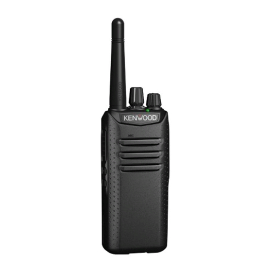
ORIENTATION Microphone Speaker Antenna Battery pack a Selector Rotate to change the operating channel. b LED indicator For the LED indicator status, refer to page 13. c Power switch/ Volume control Turn clockwise to switch ON the transceiver. To switch OFF the transceiver, turn counterclockwise until a click sounds. -
Page 9: Programmable Functions
PROGRAMMABLE FUNCTIONS The Selector, Side 1 and Side 2 keys can be programmed with the functions listed below. Ask your dealer for details on these functions. Note: ◆ The duration of pressing a key to activate a function is dependent on your dealer setting. - Page 10 n Emergency Places the transceiver into Emergency mode. Emergency mode is used to carry out emergency actions. Note: ◆ This function can be programmed only on the Side 1 key. n Home Channel Press this key to immediately select your home channel (pre-programmed by your dealer).
- Page 11 Scrambler Toggles the Scrambler function ON and OFF. Note: ◆ This function cannot be used in certain countries. Contact your KENWOOD dealer for further information. n Squelch Off Press to hear background noise. Press this key again to return to normal operation.
-
Page 12: Basic Operation
BASIC OPERATION SWITCHING POWER ON/OFF Turn the Power switch/ Volume control clockwise to switch the transceiver ON. Turn the Power switch/ Volume control counterclockwise fully to switch the transceiver OFF. Transceiver Password If your transceiver is password protected, the LED will light blue when you turn the transceiver ON. -
Page 13: Receiving
• For best sound quality at the receiving station, hold the microphone approximately 1.5 inches (3 cm to 4 cm) from your mouth. RECEIVING Select the desired zone and channel. If signaling has been programmed on the selected channel, you will hear a call only if the received signal matches your transceiver settings. -
Page 14: Voice Operated Transmission (Vox)
VOICE OPERATED TRANSMISSION (VOX) VOX operation allows you to transmit hands-free. This feature must first be activated by your dealer, and can only be used if you are using a supported headset. VOX can be turned off for specific channels by your dealer. To activate VOX and set the VOX Gain level, perform the following steps: 1 Connect a headset to the transceiver. -
Page 15: Fleetsync: Alphanumeric 2-Way Paging Function
FleetSync: ALPHANUMERIC 2-WAY PAGING FUNCTION FleetSync is an Alphanumeric 2-way Paging Function and is a protocol owned by JVC KENWOOD Corporation. SELCALL (SELECTIVE CALLING) A Selcall is a voice call to a particular station or to a group of stations. -
Page 16: Scan
SCAN Scan monitors for signals on the transceiver channels. While scanning, the transceiver checks for a signal on each channel and only stops if a matching signal is present. To start/ stop scanning, press the key programmed as [Scan]. • When a signal is detected, Scan pauses at that channel. -
Page 17: Advanced Operations
ADVANCED OPERATIONS EMERGENCY CALLS If your transceiver has been programmed with the Emergency function, you can make emergency calls. 1 Press and hold the key programmed as [Emergency]. • Ask your dealer for the length of time necessary to hold this key before the transceiver enters Emergency mode. -
Page 18: Monitor/ Squelch Off
MONITOR/ SQUELCH OFF You can use the key programmed as [Monitor] or [Squelch Off] to listen to weak signals that you cannot hear during normal operation and to adjust the volume when no signals are present on your selected channel. Your dealer can program a key with one of 4 functions: •... -
Page 19: Dmr
DMR is a generic name for a digital communication system protocol utilizing 4-level FSK. In a DMR Conventional system, communications are realized by sending and receiving digital signals on a DMR digital channel. Using a DMR ID (Unit ID or Group ID) allows the various communications INDIVIDUAL/ GROUP CALLS Each channel is set up with an individual or group ID list number. -
Page 20: Background Operations
BACKGROUND OPERATIONS TIME-OUT TIMER (TOT) The Time-out Timer is used to prevent you from using a channel for an extended duration. If you continuously transmit for a preset time, the transceiver will stop transmitting and a warning tone will sound. Release the PTT switch to stop the tone. -
Page 21: Ptt Id
PTT ID PTT ID is the transceiver unique ID code which is sent each time the PTT switch is pressed and/or released. Note: ◆ PTT ID can be made only in analog operation. SIGNALING QT/ DQT The Encoder/Decoder function uses QT/ DQT to segregate talk groups, so users only hear calls from their own group. - Page 22 © 2017...