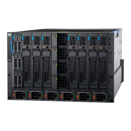
Dell EMC PowerEdge MX7000 Quick Start Manual
Hide thumbs
Also See for EMC PowerEdge MX7000:
- Installation and service manual (68 pages) ,
- Manual (48 pages) ,
- Field service manual (89 pages)

Related Manuals for Dell EMC PowerEdge MX7000


Summary of Contents for Dell EMC PowerEdge MX7000
- Page 1 Dell EMC PowerEdge MX7000 Enclosure Cabling Instruction for –48 V DC Power Supply Regulatory Model: E44S Regulatory Type: E44S001 October 2021 Rev. A00...
- Page 2 A WARNING indicates a potential for property damage, personal injury, or death. © 2021 Dell Inc. or its subsidiaries. All rights reserved. Dell, EMC, and other trademarks are trademarks of Dell Inc. or its subsidiaries. Other trademarks may be trademarks of their respective owners.
- Page 3 Contents Chapter 1: About this document....................4 Chapter 2: Input requirement......................5 Chapter 3: Assembling the -48V DC power input connector and cables......... 6 Contents...
- Page 4 Damage due to servicing that is not authorized by Dell is not covered by your warranty. Read and follow the safety instructions that are shipped with your product.
- Page 5 ● Current consumption: 83.2 A maximum ● Kit Contents: 1. DC-IN connector (1) per each PSU - Dell Part # PXNKY NOTE: Each PXNKY includes 2 pieces of Panduit 2 AWG straight, 2-hole lug # LCC2-14AW-Q, for use in crimping lug to each 2 AWG power input cable (customer provided).
- Page 6 Assembling the -48V DC power input connector and cables About this task NOTE: This product is intended to be used in CBN (Common Bonding Network) applications. NOTE: Each MX7000 chassis requires 2 earth-ground cable assemblies. Steps 1. Install the chassis into the rack by using rails, and then attach the strain-relief bar. For more information, see the Rail Installation Guide shipped with rail kit.
- Page 7 Figure 2. Removing the two 1.5 mm hex screws and separate the housing 9. Use 10 mm socket or wrench to remove four M6 nuts, and then remove two Panduit straight 2-hole lugs to assemble the power cables. 10. Strip insulation 1.25 inches (31.75 mm) from ends of 2 AWG -48V DC red and black stranded power cables. 11.
- Page 8 15. Slide the 3 piece housing components in place, and then using the 1.5 mm hex wrench tighten the screws on the RTN side. Figure 4. Attaching each -48V and RTN housing, tightening the screws on the RTN side 16. Repeat the same process for each PSU. 17.
- Page 9 Figure 6. Tighten the threaded screw on the -48V side 20. Open the clamp-on ferrite (like a clam-shell), wrap it around both “-48V” and “RTN” cables. 21. Place the ferrite as close as possible to the strain-relief bar, and then close the ferrite. Ensure the latch snaps into locked position.