Dell PowerEdge MX7000 Manual
Hide thumbs
Also See for PowerEdge MX7000:
- Installation and service manual (68 pages) ,
- Quick start manual (9 pages) ,
- Field service manual (89 pages)
Table of Contents
Advertisement
Quick Links
Advertisement
Table of Contents

Related Manuals for Dell PowerEdge MX7000


Summary of Contents for Dell PowerEdge MX7000
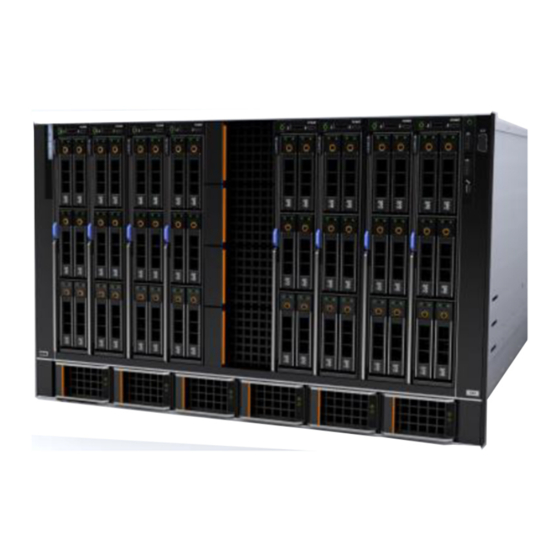
- Page 1 Technical Guide Dell PowerEdge MX7000 Next Generation Modular Platform, the Dell EMC Poweredge MX7000 hosts flexible blocks of server and storage resources while providing outstanding efficiencies through shared power, cooling, networking, I/O, and management within the chassis itself.
- Page 2 © 2018 Dell Inc. or its subsidiaries. All rights reserved. Dell, EMC, and other trademarks are trademarks of Dell Inc. or its subsidiaries. Other trademarks may be trademarks of their respective owners. 2018 - 08 Rev. A00...
-
Page 3: Table Of Contents
Contents 1 System overview ......................6 ..................................6 Introduction ................................7 New technologies 2 System features......................8 ................................8 Product comparison ..................................9 Specifications 3 Chassis view and features....................10 .............................. 10 Front view of the enclosure .................................11 Left control panel .............................. - Page 4 ..................................20 Storage Sled ..................................21 I/O Modules .................................21 Power Supplies ....................................21 Fans 8 Rail kit........................... 22 9 Power, thermal, and acoustics ..................23 ....................................23 Power ................................23 Power Supply .................................... 24 Thermal ...........................24 Ambient Temperature Requirements ..................................25 Acoustics ............................25 Deployment Environment .............................
- Page 5 ............................47 ProSupport One for Data Center ............................... 47 Support Technologies ................................47 SupportAssist .................................. 48 TechDirect ............................48 Additional professional services ..............................48 Dell Education Services ......................48 Dell EMC Global Infrastructure Consulting Services ............................48 Dell EMC Managed Services...
-
Page 6: System Overview
System overview The PowerEdge MX portfolio delivers a fully managed, high performance system that will free up valuable IT resources and personnel so you can focus on innovation. Break free from the bounds of technology silos and routine, daily and time consuming operational management to realize your IT and digital business transformations. -
Page 7: New Technologies
New technologies The following are the new technologies featured on the PowerEdge MX7000: Table 1. New technologies New technology Detailed description Form factor The MX7000 has all new chassis, sled and I/O module form factors I/O Fabrics The MX7000 support flexible I/O Fabrics... -
Page 8: System Features
System features The MX7000 enclosure has the following features: • Sleds – 8 single wide or 4 double wide sleds – Double wide sleds in slots 1-2, 3-4, 5-6, 7-8 • Power supply units – Up to 6 front loading power supply units •... -
Page 9: Specifications
Specifications Table 3. Technical specifications Features Specifications Form factor 7U rack Sled orientation Vertical Sled support Up to 8 standard-height, or 4 double-wide, or 16 half-height sleds I/O modules 3+3 (A/B/C). A and B direct I/O Ethernet interconnect. C is midplane-based fibre channel or SAS interconnect. -
Page 10: Chassis View And Features
Chassis view and features The MX740c is a full-height, two socket compute sled for the MX7000 chassis. Front view of the enclosure Figure 1. Front view of the enclosure Left control panel Single-width compute sled Sled blank Front fan (4) Double-width compute sled Single-width storage sled Right control panel... -
Page 11: Left Control Panel
Left control panel Figure 2. Left control panel - Status LED Table 4. Left control panel - LED indicator description Indicator Description Status System health Blinks amber for 2 seconds and is OFF for 1 second when the chassis health has degraded. By default, the LED is unlit. - Page 12 Figure 3. Left control panel - LCD options Table 5. Left control panel - LCD panel description Indicator Description Status LCD with Quick LCD enabled with Quick Sync module Sync LCD without LCD without Quick Sync module Quick Sync System ID This option is a button/indicator on the LCD panel to identify the chassis, or choose specific indicator on LCD sleds to identify.
-
Page 13: Right Control Panel
Indicator Description Status System ID Indicator status Description indicator/ Identification Blinking blue System ID is active. indicator Blinking amber Chassis alerts are present. Error indicator The error indicator is displayed on the LCD when there are any critical/warning alerts on the enclosure. -
Page 14: Back View Of The Enclosure
Back view of the enclosure Figure 5. Back view of the enclosure Slot for Fabric A1 Slot for Fabric A2 Rear fans (5) Slot for Fabric B1 Slot for Fabric B2 Slot for Fabric C2 Power cord connection status LED Power supply input sockets (6) Management Module 2 Management Module 1... -
Page 15: Internal Architecture
Internal Architecture The following sections contain information about the internal architecture of Dell EMC PowerEdge MX7000 system. The following diagram is a simplified view of the MX7000 system, showing some of the modules and their interconnection. Figure 6. Internal Architecture... -
Page 16: System Interconnection
System interconnection Power supply AC connection The PSUs are accessed from the front, however the AC power cable connection is at the rear of the chassis. There are six C22 inlet connectors, three on the rear left, and three on the rear right side. Each PSU has an associated AC good LED located next to its associated plug. -
Page 17: Input Output Fabrics
Input output fabrics The following sections contain information about Dell EMC PowerEdge MX7000 Input output fabrics. Input output fabrics The internal connection of the main I/O subsystem in MX7000 enclosure is referred to as fabric A and B. These fabrics are connected using a direct orthogonal connection between sleds in the front of the chassis and I/O fabric modules in the rear. -
Page 18: Other I/O Modules
Compute sled IOM x1 (top) IOM x2 (bottom) Table 7. Compute sleds with quad-port mezzanine cards mapping Compute sled IOM x1 (top) IOM x2 (bottom) 1, 9 1, 9 2, 10 2, 10 3, 11 3, 11 4, 12 4, 12 5, 13 5, 13 6, 14... -
Page 19: Storage Fabrics
Storage fabrics The following sections contain information about Dell EMC PowerEdge MX7000 storage fabrics. Storage fabric Power distribution The internal connection of the storage subsystem in the MX7000 enclosure is referred to as Fabric C. This fabric is connected on the Main DB between sleds in the front of the MX7000 enclosure and I/O modules in the rear. -
Page 20: System Modules
System Modules The following sections contain information about Dell EMC PowerEdge MX7000 system modules. Management Module (MM) The MX9002m Management Module (MM), or MM, essentially controls the overall chassis power, cooling, and physical user interfaces such as the front panel. It also contains the Ethernet switch used by the management network (Fab-D) and external Ethernet ports. -
Page 21: I/O Modules
I/O Modules The I/O Modules (IOMs) support either a Fabric A/B interconnect or a Fab-C interconnect. The Fab A/B IOMs span the entire width of the chassis, using direct orthogonal connections to the compute sleds. When installing these, the IOM will engage simultaneously with the Vertical PDB and the sleds. -
Page 22: Rail Kit
Rail kit A static rail kit will be supported for the chassis. Due to the overall weight, there is no support for 2-post racks. A strain relief bar will be provided for power cables. This bar adds 95mm of additional depth to the system, and therefore works best in 1200mm depth racks. -
Page 23: Power, Thermal, And Acoustics
Power, thermal, and acoustics Power Power Supply The MX7000 Power Supplies will utilize a new front-loading form factor developed for the MX portfolio. Up to six PSUs plug into the front of the chassis. These mate directly with connectors on the Main DB. The AC connections come from the rear of the chassis cabling to connections on the PDB. -
Page 24: Thermal
Ambient Temperature Requirements In general the EMC PowerEdge MX7000 shall support an ambient operating temperature of 10° C to 35° C Some module configurations (e.g., compute sleds with special high wattage CPU SKU's) aren't able to support 35° C ambient with full performance. -
Page 25: Acoustics
MX7000 infrastructure is designed for use in unattended data center environments; its acoustical output will be too loud for office areas in all configurations. Dell EMC provides options for the customer to reduce or limit acoustical output for attended data center applications, including: configuration restrictions, sound cap profile (iDRAC), and a hardware acoustical baffle. -
Page 26: Acoustical Baffle
NOTE: Sled Configuration Details Minimum: Each MX740c is configured with 2x 85W CPUs, 12x 16 GB DIMMs, 2x 2.5” SATA HDDs, 1x 25Gb Mezz card, 1x H740 PERC Typical: Each MX740c is configured with 2x 145W CPUs, 12x 32 GB DIMMs, 6x 1600 GB SAS SSD, 2x 25GB Mezz cards, 1x H740P PERC, 1x Fiber-channel mini Mezz Each MX840c is configured with 4x 165W CPUs, 48x 16 GB DIMMs, 8x 1600 GB NVMe SSD, 4x 25GB Mezz cards, 2x Fiber-channel mini Mezz, 1x H740P PERC... -
Page 27: Openmanage Systems Management
The integrated Dell Remote Access Controller (iDRAC) with Lifecycle Controller provides embedded management in every Dell EMC PowerEdge server. It provides functionality that helps you deploy, update, monitor and maintain Dell EMC PowerEdge servers with or without a systems management software agent, and because it is embedded, iDRAC doesn’t need an operating system or hypervisor to start working. - Page 28 performed within a single console that unifies management of tower, rack, and modular platforms. OpenManage Enterprise helps in standardizing and supporting IT management policies and practices. The OpenManage Enterprise console simplifies and strengthens the current capability of OpenManage Essentials in the following areas: •...
- Page 29 Dell EMC. Configuration compliance policies Configuration compliance policies allow IT Enables a simple method to monitor the Administrators to establish one or more...
-
Page 30: Openmanage Enterprise - Modular Edition
It runs on the PowerEdge M9002m management module (MM) firmware. OME-Modular facilitates configuration and management of a stand-alone PowerEdge MX7000 chassis or group of MX7000 chassis from one Graphical User Interface (GUI). You can use OME-Modular to deploy servers and update firmware. You can also manage the overall health of the chassis and the chassis components such as compute sleds, networks, input or output modules (IOMs), and storage devices. -
Page 31: Openmanage Console
The central console in a systems management solution is often referred to as the one-to-many console. The central console provides a rapid view and insight into the overall health of all systems in the IT environment. The Dell EMC systems management portfolio includes several powerful consoles, depending upon your needs, including the following: •... -
Page 32: Openmanage Integrations
OpenManage Ansible Modules OpenManage Connections With OpenManage Connections, you can extract rich information about the health and behavior of Dell EMC servers and storage to more effectively monitor, manage and troubleshoot Dell EMC systems in multi-vendor hardware, OS, hypervisor and Open Source environments. -
Page 33: Appendix A. Additional Specifications
Appendix A. Additional specifications The following sections contain information about additional system specifications. Population rules System modules must be populated as described in the following table: Table 12. MX7000 population rules Category Maximum population Blanks All the empty slots in the MX7000 enclosure must be populated with blanks (Sled, IOM, EC, and PSU). This is required for proper cooling of the enclosure and components. -
Page 34: Psu Redundancy And Population Rules
Category Maximum population The second processor must be installed on the compute node to support Fabric-B Mezzanine / IOM and Fabric-C Mezzanine / IOM. PSU redundancy and population rules The number of PSUs required depends on the enclosure configuration and redundancy required. The minimum requirement is two PSUs. -
Page 35: Chassis Dimensions
Chassis dimensions Figure 8. Dimensions of the PowerEdge MX7000 Table 14. Dimensions of the PowerEdge MX7000 Description Dimension 482 mm (18.98 inches) 445 mm (17.52 inches) 307.4 mm (12.11 inches) 816.6 mm (32.15 inches) 811.6 mm (31.96 inches) Chassis weight Table 15. -
Page 36: Fan Specifications
Fan specifications The PowerEdge MX7000 enclosure supports four front accessible hot-swap cooling fans and five rear accessible hot-swap cooling fans. The cooling fan assembly ensures that the key components of the server such as the sleds, Fabrics, and I/O modules get adequate air circulation to keep them cool. -
Page 37: Poweredge Mx Modules Ports And Connectors
NOTE: You must use a mini DP dongle to connect the enclosure to a VGA display. PowerEdge MX modules ports and connectors PowerEdge MX740c Table 18. PowerEdge MX740c externally accessible connectors Connector Description • One USB 3.0-compliant port on the front of the sled. USB ports •... -
Page 38: Poweredge Mx5108N
Connector Description – 1 x 100 GbE – 2 x 50 GbE – 4 x 10 GbE – 4 x 25 GbE – 8 x 8/ 16/ 32 GbE Fibre Channel mode PowerEdge MX5108n Table 22. PowerEdge MX5108n externally accessible connectors Connector Description •... -
Page 39: Environmental Specifications
8, 16, 32 NOTE: 1920 x 1080 and 1920 x 1200 resolutions are only supported in reduced blanking mode. Environmental specifications NOTE: For additional information about environmental measurements for specific system configurations, see Dell.com/ poweredgemanuals. Table 27. Temperature specifications Temperature... -
Page 40: Standard Operating Temperature
Table 31. Maximum altitude specifications Maximum altitude Specifications Operating 3048 m (10,000 ft) Storage 12,000 m (39,370 ft) Table 32. Operating temperature derating specification Operating temperature Specifications derating Up to 35°C (95°F) Maximum temperature reduces by 1°C/300 m (1°F/547 ft), above 950 m (3,117 ft). 35°C to 40°C (95°F to Maximum temperature reduces by 1°C/175 m (1°F/319 ft), above 950 m (3,117 ft). -
Page 41: Particulate And Gaseous Contamination Specifications
• Redundant power supplies are required. Expanded operating temperature restrictions For more information about the expanded operating temperature restrictions, see the Installation and Service Manual for the PowerEdge MX sleds at Dell.com/poweredgemanuals. Table 35. Expanded operating temperature restrictions System C40E45... -
Page 42: Appendix B. Standards Compliance
Appendix B. Standards compliance Table 38. Industry standard documents Standard URL for information and specifications ACPI Advance Configuration and Power Interface Specification, acpi.info v2.0c Ethernet IEEE 802.3-2005 standards.ieee.org/getieee802/802.3.html HDG Hardware Design Guide Version 3.0 for Microsoft Windows microsoft.com/whdc/system/platform/pcdesign/desguide/ Server serverdg.mspx IPMI Intelligent Platform Management Interface, v2.0 intel.com/design/servers/ipmi DDR4 Memory DDR4 SDRAM Specification... -
Page 43: Appendix C. Additional Resources
This document ships with the system, is also available in PDF Dell.com/Support/Manuals format online, and provides information on system updates. Energy Smart Solution Advisor The Dell online ESSA enables easier and more meaningful Dell.com/calc (ESSA) estimates to help you determine the most efficient configuration possible. -
Page 44: Appendix D. Support And Deployment Services
From simple to the most complex server installations and software integration, we take the guess work and risk out of deploying your new server technology. Who's better suited to implement the latest Dell EMC servers than the Dell EMC elite deployment engineers who do it every day? Figure 9. -
Page 45: Residency Services
Remote Consulting Services When you are in the final stages of your PowerEdge server implementation, you can rely on Dell Remote Consulting and our certified technical experts to help you optimize your configuration with best practices for your software, virtualization, server, storage, networking, and systems management. -
Page 46: Prosupport Plus
• Access to senior ProSupport engineers for faster issue resolution • Personalized, preventive recommendations based on analysis of support trends and best practices from across the Dell EMC customer base to reduce support issues and improve performance • Predictive analysis for issue prevention and optimization enabled by SupportAssist •... -
Page 47: Prosupport One For Data Center
This offering is built on standard ProSupport components that leverage our global scale but are tailored to your company's needs. While not for everyone, it offers a truly unique solution for Dell EMC's largest customers with the most complex environments. -
Page 48: Techdirect
• Request technical support • Integrate APIs into your help desk Or, access all your Dell EMC certification and authorization needs. Train your staff on Dell EMC products as TechDirect allows you to: • Download study guides • Schedule certification and authorization exams •...