Advertisement
INSTRUCTION MANUAL
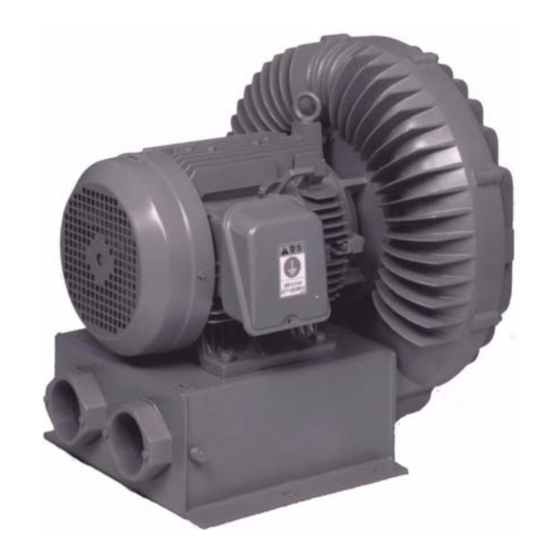
Thank you for the recent purchase of a
HITACHI Vortex Blower. Please read this
instruction
manual
installation, maintenance and inspection
guidelines of the HITACHI Vortex Blower.
After reading this instruction manual,
please
keep
it
on
reference.
REQUEST
This
instruction
delivered to the personnel operating the
HITACHI Vortex Blower.
Chapter
Description
1. SAFETY INFORMATION -------------------------------------------------------------------------------------- 2
2. PRE-INSTALLATION PROCEDURE----------------------------------------------------------------------- 7
3. INSTALLATION --------------------------------------------------------------------------------------------------- 9
4. WIRING ------------------------------------------------------------------------------------------------------------ 13
5. START UP --------------------------------------------------------------------------------------------------------- 17
6. OPERATION AND DAILY INSPECTION --------------------------------------------------------------- 18
7. SECTION DRAWING OF VORTEX BLOWER -------------------------------------------------------- 19
8. TROUBLESHOOTING ---------------------------------------------------------------------------------------- 21
HITACHI
VORTEX BLOWER
E-U
E2
carefully
for
hand
for
future
manual
should
be
CONTENTS
SERIES
SERIES
- 1 -
VB-060-E2
Page
NA201X
Advertisement

Related Manuals for Hitachi E-U Series


Summary of Contents for Hitachi E-U Series
-
Page 1: Table Of Contents
INSTRUCTION MANUAL HITACHI VORTEX BLOWER SERIES SERIES Thank you for the recent purchase of a HITACHI Vortex Blower. Please read this instruction manual carefully installation, maintenance and inspection guidelines of the HITACHI Vortex Blower. After reading this instruction manual, please... -
Page 2: Safety Information
1. SAFETY INFORMATION Safety is extremely important. To ensure safe operation, many important safety messages are provided in this instruction manual and on the Vortex Blower. Please read and follow all safety messages carefully. = SAFETY ALERT SYMBOL The safety alert symbol is used to alert personnel of hazards of extreme danger. The safety alert symbol and the word “WARNING”... - Page 3 Using a damaged Vortex Blower can lead to personal injury, fire to the machinery, etc. Do not make any modifications to the Vortex Hitachi does not take any responsibility for Blower. any modifications made to the Vortex Blower. Do not place any obstacles in front of the...
- Page 4 WARNING UNPACKING Concern/Alarm Possible Consequences Improper handling of the packing box may Before handling the packing box or crate of the lead to personal injury. Vortex Blower, verify that the packing box or crate is right side up. Verify that the Vortex Blower is the correctly Installing the wrong type of Vortex Blower can ordered product.
- Page 5 WARNING PIPING & WIRING Concern/Alarm Possible Consequences Connect the power supply cable correctly. If the power supply is installed incorrectly, (see page 13) electric shock or fire to the machinery can occur. Do not bend or pull the power supply cable or Bending or pulling wires can lead to electric lead wires of the Vortex Blower.
- Page 6 WARNING MAINTENANCE & INSPECTION Concern/Alarm Possible Consequences Connect the power supply cable correctly. If the power supply is installed incorrectly, electric shock or fire to the machinery can occur. Do not touch the terminals during Touching the terminals can lead to electric measurement of the motor insulation shock.
-
Page 7: Pre-Installation Procedure
High starting frequency will lead to motor damage. (NOTE: The permissible starting frequency varies depending on the operating conditions. Please contact the local Hitachi distributor for more details). 3. Operable Range (Do not use the Vortex Blower if scheduled performance is not... - Page 8 5. High Discharge Air Temperature Take precautions against high discharge air temperature especially in a small flow application. (Please see the chart below.) Excessive Heat Rise in Discharge temperatures Chart of the Vortex Blower. (138.9) VB-004(S)E-U 60 Hz VB-019(S)E-U VB-030E-U (111.1) (83.3) (55.6)
-
Page 9: Installation
3. INSTALLATION 1. Lifting the Vortex Blower To lift the Vortex Blower by crane, please review the table and illustration below. Vortex Blower Hangar Construction Table Model Motor Blower Proper Lifting Procedure VB-001SE-U, VB-002SE-U, VB-002SE-U, No hanger No hanger By Hand VB-004(S)E-U, VB-007(S)E-U VB-019(S)E-U,... - Page 10 Less than 60° Eyebolt Eyebolt Do not use motor hooks. Do not use motor hooks. Fig.3.2 VB-040 to 080-E2 fig.3.3 VB-110-E2 2. Installation Direction • In order to keep the shaft of the Vortex Blower level, mount the Vortex Blower horizontally (see Horizontal Installation below).
- Page 11 4. Installation Piping Install a filter if • Use lightweight, flexible pipes Install a pressure gauge in foreign objects, such if possible. order to check the maximum • If steel pipes are used, install as granules, dirt or operating static pressure.
- Page 12 During unavoidable intermittent operation, a changeover valve system can be installed to prevent this event from occurring (see the illustrations below). To operate the Vortex Blower without the changeover valve system, please contact the local Hitachi distributor. Intermittent air requirements Intermittent suction or discharge requirements...
-
Page 13: Wiring
4. WIRING 1. Be sure to use the proper wiring equipment and tools. Follow the electrical equipment standards, internal wiring regulations and regulations of the local power utilities company. All wiring must conform to local and national electric codes. Please contact a certified electrician. 2. - Page 14 1 Phase Wiring Reference Data (60Hz) Full Load Motor Output Standard Locked Minimum AMPS Model No. Insulation Phase Voltage Rotor Wire Size (Vacuum) AMPS(A) VB-001SE-U AWG14 VB-002SE-U AWG14 10.6 VB-003SE-U AWG14 20.0 VB-004SE-U AWG14 10.0 44.0 VB-007SE-U 0.75 AWG14 22.0 100.0 VB-019SE-U 2 1/2...
- Page 15 3 Phase Wiring Reference Data (60Hz) Full Load Motor Output Standard Locked Minimum AMPS Model No. Insulation Phase Voltage Rotor Wire Size (Vacuum) AMPS(A) VB-004E-U AWG14 0.85 15.0 VB-007E-U 0.75 17.0 AWG14 45.0 VB-019E-U 2 1/2 AWG14 54.0 27.0 VB-030E-U AWG14 VB-040-E2 AWG9...
- Page 16 Motor control wiring diagram for 3 Phase models for standard connection Electromagnetic Earth leakage Switch Breaker Class 3 Ground Example of protection equipment NOTES: (1) Indicate the minimum wiring size range. (2) Automatic thermal protection In models VB-001SE-U thru VB-007SE-U, the thermal protector is in direct line with the power to the motor windings.
-
Page 17: Start Up
5. START UP Follow the steps below during start up of the Vortex Blower. 1. Power Supply Check Check: If current does not flow through the • Switch Capacity wire because of a break in the power • Ground supply or a contact defect in a •... -
Page 18: Operation And Daily Inspection
6. OPERATION AND DAILY INSPECTION OPERATION 1. Continuous Operation Limitations • Continuous operation should be maintained on or within the solid line of the performance curve. • Maximum operating pressure is indicated on the Vortex Blower nameplate. • Check the maximum operating pressure by using a pressure gauge. •... -
Page 19: Section Drawing Of Vortex Blower
7. SECTION DRAWING OF VORTEX BLOWER Models VB-001SE-U thru VB-003SE-U Fig. 7.1 Models VB-004E-U thru VB-040-E2 Fig. 7.2 - 19 -... - Page 20 Models VB-060-E2 thru VB-110-E2 Fig. 7.3 - 20 -...
-
Page 21: Troubleshooting
Type of Problem Cause Corrective Action Terminal short circuit Repair or replace the wiring. Power switch turns off Contact the local Hitachi Stator coil short circuit distributor for repair. Contact defect in switch Replace the contact or switch. Power supply has been Inspect and fix the power as damaged. - Page 22 Voltage has dropped or Contact the local power utilities become unbalanced company. Foreign objects have been Contact the local Hitachi Motor has overheated inhaled, causing restriction distributor for repair. to the impeller. Ambient temperature in the Improve the ventilation to the...
- Page 23 - 23 -...
- Page 24 Note the Vortex Blower’s specifications below for future reference. Model Vortex Blower MFG.No. Installation Date month year Start Up Date month year Local Hitachi Distributor Phone Primary Contact: - 24 -...