Table of Contents
Advertisement
Quick Links
S9360B, S9361B, S9370B, S9371B,
S9380B, S9381B
Integrated Water Heater Controllers
APPLICATION
These integrated water heater control modules
provide ignition sequence, flame monitoring and
safety shutoff for either intermittent pilot spark
ignition or direct hot surface ignition heating
systems. They also provide limit rated water
temperature control and display interface capability
for either "on-board" or remote user interface
applications. Cover shown is optional.
• S9360B—Spark Ignition, Intermittent Pilot, Remote
Display, Water Heater Applications.
• S9361B—Spark Ignition, Intermittent Pilot, "On
board" Display, Water Heater Applications.
• S9370B—Hot Surface Ignition, Remote Display,
Water Heater Applications.
• S9371B—Hot Surface Ignition, "On board" Display,
Water Heater Applications.
• S9380B—Direct Spark Ignition, Remote Display,
Water Heater Applications
• S9381B—Direct Spark Ignition, "On board" Display,
Water Heater Applications
• All models are enabled with EnviraCOM™
communication capability to support remote
monitoring and diagnostics.
• Limit-rated Temperature Sensing Probe.
• One or Two Sensor Models.
INSTALLATION INSTRUCTIONS
SPECIFICATIONS
IMPORTANT:
The specifications given in this publication do
not include normal manufacturing
tolerances. Therefore, an individual unit may
not match the listed specifications exactly.
Also, this product is tested and calibrated
under closely controlled conditions, and some
minor differences in performance can be
expected if those conditions are changed.
Model Numbers
S—Switching Control
9
3—Integrated Hydronic Control Platform
6—Spark Ignition
7—Hot Surface Ignition
8—Direct Spark Ignition
0—Remote Display Required
1—Integrated On-Board Display
A—Boiler Control
B—Water Heater Control
C—Pool Heater Control
S
9
3
6
0
A
Dimensions:
See Fig. 1.
1—No Circulator
2—On/Off Circulator
3—Variable Speed Circulator
1
000
69-1792-09
Advertisement
Table of Contents

Related Manuals for Honeywell S9360B


Summary of Contents for Honeywell S9360B
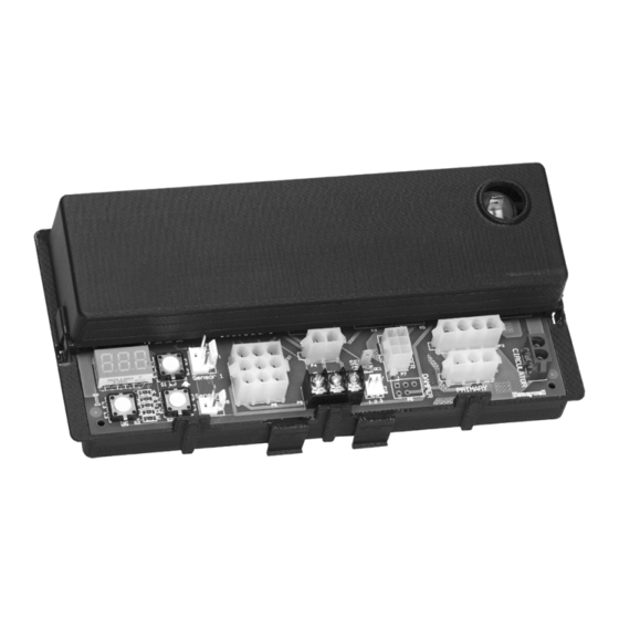
- Page 1 1—Integrated On-Board Display for either “on-board” or remote user interface applications. Cover shown is optional. A—Boiler Control B—Water Heater Control • S9360B—Spark Ignition, Intermittent Pilot, Remote C—Pool Heater Control Display, Water Heater Applications. • S9361B—Spark Ignition, Intermittent Pilot, “On 1—No Circulator board”...
- Page 2 S9360B, S9361B, S9370B, S9371B, S9380B, S9381B INTEGRATED WATER HEATER CONTROLLERS 4-3/8 (111) 2-25/64 (61) [2] 3-11/32 (85) [2] 19/32 8-45/64 (15) [2] (221) 19/32 (15) [2] 1-3/8 (35) (16) M24217A Fig. 1. S936X Integrated Water Heater Controller, dimensions in in. (mm).
-
Page 3: Planning The Installation
S9360B, S9361B, S9370B, S9371B, S9380B, S9381B INTEGRATED WATER HEATER CONTROLLERS Table 1. Recommended ignition cables. Approvals: Varies with control model. Voltage Temperature Rating ANSI Z21.20 Automatic Gas Ignition Systems and Rating Components. Cable Type (rms) °C °F ANSI Z21.23 Gas Appliance Thermostats. - Page 4 S9360B, S9361B, S9370B, S9371B, S9380B, S9381B INTEGRATED WATER HEATER CONTROLLERS Heat shielding, and air circulation may be necessary to protect the controls. Proper insulation or shielding The controls can be damaged by excessively high should b provided by the appliance manufacturer;...
-
Page 5: Installation And Checkout
S9360B, S9361B, S9370B, S9371B, S9380B, S9381B INTEGRATED WATER HEATER CONTROLLERS INSTALLATION AND CHECKOUT When Installing This Product… Maintenance Requirements in Severe Environments 1. Read these instructions carefully. Failure to follow them could damage the product or cause Regular preventive maintenance is important in any a hazardous condition. -
Page 6: Wire The System
S9360B, S9361B, S9370B, S9371B, S9380B, S9381B INTEGRATED WATER HEATER CONTROLLERS WATER HEATER CONTROL M24229 Fig. 2. Align module with slots in control box. Wire the System 3-15/16 (100) WARNING 5/32 (4) Electrical Shock Hazard. 5/8 (16) Can cause severe injury, death or property damage. - Page 7 S9360B, S9361B, S9370B, S9371B, S9380B, S9381B INTEGRATED WATER HEATER CONTROLLERS IMPORTANT 1. Use wire suitable for the temperatures near the 1. All wiring must comply with applicable local HSI igniter. electrical codes and ordinances. 2. Use wire suitable for the voltage ratings of the 2.
- Page 8 S9360B, S9361B, S9370B, S9371B, S9380B, S9381B INTEGRATED WATER HEATER CONTROLLERS Transformer: Add current ratings of module, gas control, vent damper and any other components of the control system to determine transformer size requirements. 69-1792—09...
-
Page 9: Wiring Diagrams
S9360B, S9361B, S9370B, S9371B, S9380B, S9381B INTEGRATED WATER HEATER CONTROLLERS Wiring diagrams (see Fig. 4 to 6.) FLAME SPARK SENSE IGNITER CIRCULATOR INDUCER 24 VAC TRANSFORMER DAMPER ENVIRACOM DIAGNOSTIC ENVIRACOM DISPLAY CONTROL PRESSURE SWITCH LIMIT SWITCH SENSOR 1 SENSOR 2... - Page 10 S9360B, S9361B, S9370B, S9371B, S9380B, S9381B INTEGRATED WATER HEATER CONTROLLERS SPARK FUME IGNITER SENSE INDUCER 24 VAC TRANSFORMER DAMPER ENVIRACOM DIAGNOSTIC E-COM PRESSURE SWITCH LIMIT SWITCH CONTROL TSTAT SWITCH SENSOR 1 SENSOR 2 OPTIONAL DEPENDING ON CONFIGURATION M27380 Fig. 5. Direct spark ignition (S938X).
- Page 11 S9360B, S9361B, S9370B, S9371B, S9380B, S9381B INTEGRATED WATER HEATER CONTROLLERS CIRCULATOR INDUCER HOT SURFACE IGNITER FLAME SENSE 24 VAC TRANSFORMER ENVIRACOM DIAGNOSTIC ENVIRACOM DISPLAY CONTROL PRESSURE SWITCH LIMIT SWITCH SENSOR 1 SENSOR 2 M24218A Fig. 6. Hot surface ignition wiring (S937X).
-
Page 12: Common Connectors
S9360B, S9361B, S9370B, S9371B, S9380B, S9381B INTEGRATED WATER HEATER CONTROLLERS Common Connectors Table 3. Connectors common to both spark-to-pilot and hot surface ignition options. Connection/Color Mating Plug Description Flame Sense 1 of 1 3/16 in. female quick- Connection to Flame Rod... -
Page 13: Temperature Control
S9360B, S9361B, S9370B, S9371B, S9380B, S9381B INTEGRATED WATER HEATER CONTROLLERS Table 5. Spark model specific connectors. Connection Mating Plug Description Line Voltage 1 of 4 ® Molex 50-81-1040 Input/White 2 of 4 Earth Ground 3 of 4 Earth Ground 4 of 4... -
Page 14: Location And Mounting
S9360B, S9361B, S9370B, S9371B, S9380B, S9381B INTEGRATED WATER HEATER CONTROLLERS CHECKOUT “SP_” Setpoint. “Df_” Setpoint Differential (select models). “°F_” Degrees Fahrenheit Put the system into operation and observe operation Then press the UP or DOWN button until the through at least one complete cycle to make sure that parameter has reached the desired value. -
Page 15: Operation And Checkout
S9360B, S9361B, S9370B, S9371B, S9380B, S9381B INTEGRATED WATER HEATER CONTROLLERS Mounting Sensor and OPERATION AND Thermowell CHECKOUT The remote upper temperature sensor is installed in an immersion well (Fig. 9) that extends into the tank to Operation help prevent stacking. - Page 16 S9360B, S9361B, S9370B, S9371B, S9380B, S9381B INTEGRATED WATER HEATER CONTROLLERS START CALL FOR HEAT ACTIVE (Temperature low) PREPURGE STAGE 1 Draft source energized PREPURGE (Combustion blower or damper) STAGE 2 SPARK GENERATOR POWERED Pilot valve opens. TRIAL FOR IGNITION PILOT BURNER OPERATION Pilot burner does not light.
- Page 17 S9360B, S9361B, S9370B, S9371B, S9380B, S9381B INTEGRATED WATER HEATER CONTROLLERS START IDLE ALL OUTPUTS OFF CALL FOR HEAT CHECK LEAKAGE/ CALL FOR SET FLAME BIAS HEAT LOST BIAS DONE WAIT LIMIT SWITCH CLOSE TIME OUT OR LIMIT MANUAL RESET LIMIT SWITCH CLOSE...
-
Page 18: Ignition System Checks
S9360B, S9361B, S9370B, S9371B, S9380B, S9381B INTEGRATED WATER HEATER CONTROLLERS TROUBLESHOOTING WARNING IMPORTANT The ignition circuit generates over 10,000 volts and electrical shock can result. 1. The following service procedures are provided as a general guide. Follow appliance manufac- Energize the module and listen for the audible turer’s service instructions if available. - Page 19 S9360B, S9361B, S9370B, S9371B, S9380B, S9381B INTEGRATED WATER HEATER CONTROLLERS Table 7. Error codes. Segment Display Definition Communication between the PWB and the display is corrupted. Pressure Switch failed to open (contacts stuck closed). Flame sensed out of normal sequence (before opening gas valve or after closing gas valve).
-
Page 20: Security Notice
S9360B, S9361B, S9370B, S9371B, S9380B, S9381B INTEGRATED WATER HEATER CONTROLLERS CAUSE APPEARANCE SMALL BLUE FLAME CHECK FOR LACK OF GAS FROM: • CLOGGED ORIFICE FILTER • CLOGGED PILOT FILTER • LOW GAS SUPPLY PRESSURE • PILOT ADJUSTMENT AT MINIMUM LAZY YELLOW FLAME CHECK FOR LACK OF AIR FROM: •...