Table of Contents
Advertisement
Spyder Model 5
COMPACT VAV CONTROLLER
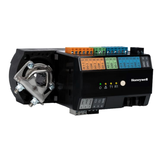
WEB-VA423B24N
Fig. 1. WEB-VA423B24N
TABLE OF CONTENTS
Trademark Information ........................................................ 1
Product description ............................................................... 1
Safety instructions ................................................................. 1
Dimensions ................................................................................ 2
Specifications ........................................................................... 3
Terminals .................................................................................... 4
Installation ................................................................................. 5
Piping ............................................................................................ 8
Power supply ............................................................................. 9
Wiring ............................................................................................ 9
Communication .................................................................... 10
Commissioning ..................................................................... 13
Operator interface LEDs ................................................... 14
Schematic Diagram ............................................................ 15
Typical VAV application - Example wiring ............... 16
Replacing actuator .............................................................. 17
Approvals, Certifications, etc. ......................................... 18
Related Technical Literature .......................................... 19
Appendix .................................................................................. 19
TRADEMARK INFORMATION
Sylk™ is a trademark of Honeywell International Inc.
BACnet®is a registered trademark of ASHRAE Inc
® U.S. Registered Trademark
Copyright © 2020 Honeywell Inc. • All Rights Reserved
PRODUCT DESCRIPTION
The WEB-VA423B24N controller is part of the
Honeywell WEBs Spyder Model 5 family. The
Honeywell Spyder Model 5 (WEB- VA423B24N)
family of unitary controllers provide flexible, freely
programmable, demand-led control that delivers
tangible benefits to reduce energy spends while
driving new levels of functionality and efficiency in
today's buildings. These scalable and freely
programmable BACnet MS/TP-based unitary
controllers utilize smart engineering and
commissioning tools and Sylk™ bus technology.
Multiple flexible configurations can be achieved to
address specific applications.
WEB-VA423B24N and replacement parts are
described in Table 1 and Table 2 on pg.2.
SAFETY INSTRUCTIONS
•
While performing any work (installation,
mounting, startup), all instructions given
by the manufacturer and the safety
instructions provided in this document
must be followed.
•
The WEB-VA423B24N compact VAV
controller must be installed and mounted
only by authorized and trained personnel.
•
If the unit is modified in any way, except by
the manufacturer, all warranties
concerning operation and safety become
invalid.
•
Make sure that applicable local standards
and regulations are always observed.
•
Use only Honeywell supplied or approved
accessories.
•
Before the system is dismantled,
disconnect the power supply by either
removing the power terminal block from
the controller, or by means of local
isolation. Read the following caution note
.
carefully.
INSTALLATION INSTRUCTIONS
CAUTION
Disconnect the power supply
before installing the WEB-
VA423B24N controller. Do not
reconnect the power supply until
you have completed the
installation.
31-00362-01
Advertisement
Table of Contents

Related Manuals for Honeywell Spyder 5


Summary of Contents for Honeywell Spyder 5
-
Page 1: Table Of Contents
BACnet®is a registered trademark of ASHRAE Inc carefully. CAUTION Disconnect the power supply before installing the WEB- VA423B24N controller. Do not reconnect the power supply until you have completed the installation. ® U.S. Registered Trademark Copyright © 2020 Honeywell Inc. • All Rights Reserved 31-00362-01... -
Page 2: Dimensions
COMPACT VAV CONTROLLER WEB-VA423B24N – INSTALLATION INSTRUCTIONS Table 1. Ordering Information Total Integrated Controller Power Digital Description no. of flow Actuator / Remarks Model supply Outputs I/Os sensor Declutch Spyder Model 5 Compact 72 hours WEB- VAV with data VA423B24N integrated retention actuator... -
Page 3: Specifications
COMPACT VAV CONTROLLER WEB-VA423B24N – INSTALLATION INSTRUCTIONS SPECIFICATIONS Real Time Clock General Operating Range: 24 hour, 365 day, multi-year For a complete list of all terminals and their calendar including day of week and configuration description of their functions, see Table 4 on pg.4. for automatic daylight savings time adjustment to occur at 2:00 a.m. -
Page 4: Terminals
COMPACT VAV CONTROLLER WEB-VA423B24N – INSTALLATION INSTRUCTIONS TERMINALS Table 4. WEB-VA423B24N: Overview of the terminals and functions Fig. 3. WEB-VA423B24N: Overview of terminals and functions Details Terminal Printing Supply Voltage (24 V) 24 V~ Supply Voltage (GND), internally connected with terminal 10, 13 & 16 24 V0 20 VDC 20 VDC power out... -
Page 5: Installation
COMPACT VAV CONTROLLER WEB-VA423B24N – INSTALLATION INSTRUCTIONS 3. Determine the direction in which the damper INSTALLATION shaft rotates to open the damper (CW or CCW) Before mounting the controller on damper shaft, (see Fig. 5). Typically, there is an etched line review the power, inputs and output specification on the end of the damper shaft that indicates on pg.3. - Page 6 COMPACT VAV CONTROLLER WEB-VA423B24N – INSTALLATION INSTRUCTIONS Mounting Actuator onto Damper Shaft WEB-VA423B24N compact VAV controller can be mounted in any orientation but should be mounted in a position that allows clearance for wiring, servicing, removal, connection of the BACnet connector and access to the service button.
- Page 7 COMPACT VAV CONTROLLER WEB-VA423B24N – INSTALLATION INSTRUCTIONS 2.3. Tighten the two mechanical end-limit rotation travel. Each “hash mark” indicator screws (Phillips #2 screwdriver; (26.5-31 on the bracket represents approximately lb.-in. [3.0-3.5 Nm] torque). 6.5° of rotation per side. • The Declutch button, when pressed, allows 2.4.
-
Page 8: Piping
COMPACT VAV CONTROLLER WEB-VA423B24N – INSTALLATION INSTRUCTIONS Best practice for zero calibration of air flow PIPING sensor Connect the air flow pickup to the two restrictor The controller must be powered up for a minimum ports on the controller. of 1 hour before performing the zero calibration for Note: the air flow sensor. -
Page 9: Power Supply
COMPACT VAV CONTROLLER WEB-VA423B24N – INSTALLATION INSTRUCTIONS POWER SUPPLY or other means for disconnecting from the power supply must have the means of General Information disconnection incorporated in the fixed To prevent a risk of injury due to electrical shock wiring. -
Page 10: Communication
COMPACT VAV CONTROLLER WEB-VA423B24N – INSTALLATION INSTRUCTIONS CAUTION Controller configurations are not necessarily limited to three devices, but the total power draw, including accessories, cannot exceed 100 VA when powered by the same transformer (U.S. only) Fig. 12. Power wiring details for one controller per transformer. Fig. - Page 11 COMPACT VAV CONTROLLER WEB-VA423B24N – INSTALLATION INSTRUCTIONS Physical limitation: NOTE 1: 32 loads as per TIA/EIA-485 standard. One • If any of the devices are electrically Spyder Model 5 controller represents ¼ load. isolated, it is recommended that those The physical limitation is important in case 3rd devices be connected to signal ground.
- Page 12 COMPACT VAV CONTROLLER WEB-VA423B24N – INSTALLATION INSTRUCTIONS Sylk Bus™ BACnet connections to the RS485 interfaces must comply with the RS485 standard. Thus, it is Sylk™ Bus capable wall modules such asTR40x / recommended that each end of every bus should T42x can be connected to the controller's Sylk™...
-
Page 13: Commissioning
COMPACT VAV CONTROLLER WEB-VA423B24N – INSTALLATION INSTRUCTIONS Wiring Method COMMISSIONING Automatic MAC Addressing NOTES: • When attaching two or more wires to the In contrast to other controllers the WEB- same terminal, other than 14 AWG (2.0 mm VA423B24N controller features automatic MAC be sure to twist them together. -
Page 14: Operator Interface Leds
Stays OFF Operation (0.5 Hz) *Please return the controller for repair. Contact Honeywell WEBs Customer Care for assistance. The ON/OFF frequencies listed in Table 8 above can be converted from "Hz" (i.e., "ON/OFF per second") to "ON/OFF per minute" by multiplying them by 60. -
Page 15: Schematic Diagram
COMPACT VAV CONTROLLER WEB-VA423B24N – INSTALLATION INSTRUCTIONS SCHEMATIC DIAGRAM Fig. 17. Schematic diagram for WEB-VA423B24N UI wiring All UI Pulse Meter (UI-1 only) 31-00362-01... -
Page 16: Typical Vav Application - Example Wiring
COMPACT VAV CONTROLLER WEB-VA423B24N – INSTALLATION INSTRUCTIONS TYPICAL VAV APPLICATION – EXAMPLE WIRING Fig. 18. WEB-VA423B24N Example wiring 31-00362-01... -
Page 17: Replacing Actuator
COMPACT VAV CONTROLLER WEB-VA423B24N – INSTALLATION INSTRUCTIONS REPLACING ACTUATOR 3. Remove the 4-pin connector that links the The integrated actuator of compact VAV can be actuator to the controller, by pulling away from replaced. To replace the actuator, follow the steps the actuator circuit board. -
Page 18: Approvals, Certifications, Etc
• FCC part 15B-compliant: This equipment has been tested and found to comply with the limits Honeywell takes compliance with REACH very for a Class B digital device, pursuant to part 15 seriously. of the FCC Rules. These limits are designed to provide reasonable protection against harmful According to Article 33 “Duty to communicate... -
Page 19: Related Technical Literature
COMPACT VAV CONTROLLER WEB-VA423B24N – INSTALLATION INSTRUCTIONS RELATED TECHNICAL LITERATURE NOTE: Table 9. Related Technical Literature • This is the accuracy of the internal sensor input (hardware + software Title Product [linearization]), only. This table does not Literature include the characteristics of the Number sensors, themselves (see section “Sensor Spyder Model 5 WEB- Compact... - Page 20 COMPACT VAV CONTROLLER WEB-VA423B24N – INSTALLATION INSTRUCTIONS NTC 20 kΩ Temp. Resistance Terminal Temp. Resistance Terminal Temp. Resistance Terminal Temp. Resistance Terminal °F (°C) [kΩ] voltage °F (°C) [kΩ] voltage °F (°C) [kΩ] voltage °F (°C) [kΩ] voltage -58 (-50) 1659 8.78 39.2 (4)
- Page 21 COMPACT VAV CONTROLLER WEB-VA423B24N – INSTALLATION INSTRUCTIONS PT 1000 Temp. Resistance Terminal Temp. Resistance Terminal Temp. Resistance Terminal °F (°C) [Ω] voltage [V] °F (°C) [Ω] voltage [V] °F (°C) [Ω] voltage [V] Temp. Resistance Terminal 50 (10) 1039 0.401 161.6 (72) 1278 0.488...
- Page 22 662 (350) 2297 0.845 476.6 (247) 1930 0.719 570.2 (299) 2117 0.784 663.8 (351) 2300 0.846 Honeywell Building Technologies Honeywell International Inc. 1985 Douglas Drive North © 2020 Honeywell International Inc. Golden Valley, MN 55422 31-00362-01 | Rev. 05-20 customer.honeywell.com...