Table of Contents
Advertisement
Quick Links
Advertisement
Table of Contents

Related Manuals for janitza MRG 512-PRO PQ Flex


Summary of Contents for janitza MRG 512-PRO PQ Flex
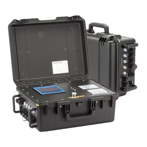
- Page 1 Mobile universal measurement device MRG 512-PRO PQ Flex Supplementary description to the operation manual UMG 512-PRO Janitza electronics GmbH Vor dem Polstück 6 D-35633 Lahnau Support tel. +49 6441 9642-22 Fax +49 6441 9642-30 E-mail: info@janitza.com Internet: http://www.janitza.com...
-
Page 2: Table Of Contents
Scope of supply - basic device Connecting the measurement case Reading out recordings MRG 512-PRO PQ Flex views Measurement transformer settings Example connection - voltage measurement Example connection - current measurement Schematic diagram: MRG 512-PRO PQ Flex design Technical data - 2 -... -
Page 3: Safety Information
Safety information Please read the operating instructions enclosed Do not use the measurement case in diligently, as well as all other publications that wet or moist environments or in the must be drawn upon for working with this vicinity of explosive gases or vapours. measurement case and the accessories. -
Page 4: Concerning This Operation Manual
PRO, please contact the support department • Keep this description and the operation manual of Janitza electronics GmbH (Tel. no. +49 6441- throughout the complete service life of the 9642-22). product and have them readily available for reference. -
Page 5: Reading Out Recordings
PC via the Ethernet connection (10) . The read-out is implemented via the GridVis software. ® MRG 512-PRO PQ Flex views LED Network OK Green: Supply UMG 512-PRO voltage is present Netz Ok Net Ok Batt. -
Page 6: Measurement Transformer Settings
Measurement transformer settings Set the following parameters at the integrated measurement transducer: • Compensate for the influence of the coil lengths through the potentiometer switching (1). To do so, set the parameters according to the table: Setting Rogowski coil 600 mm Flex-CT-1A-600 mm DIP switch •... -
Page 7: Example Connection - Voltage Measurement
Example connection - voltage measurement Voltage pickoffs with fuse Locking sleeve with bayonet catch for accommodating a fuse Max. 20mm Example connection - current measurement Voltage measurement terms Rogowski coil RCM measurement cable connections Residual current transformer not included in the scope of deliverables - 7 -... -
Page 8: Schematic Diagram: Mrg 512-Pro Pq Flex Design
Schematic diagram: MRG 512-PRO PQ Flex design Settings, parametrisation and safety information apply in accordance with the installation and operating instructions enclosed. Up to 2 residual current DIFF measurements can be selected! 0-30 MRG 512-PRO PQ Flex Switch Strommessung 1-4...