Mitsubishi Electric FR-E700 Series Installation Manualline
Hide thumbs
Also See for FR-E700 Series:
- Instruction manual (608 pages) ,
- Basic instruction manual (149 pages) ,
- Installation manuallines (38 pages)
Advertisement
INVERTER
FR-E700
INSTALLATION GUIDELINE
FR-E740-016(SC) to 300(SC)-EC
FR-E720S-008(SC) to 110(SC)-EC
Thank you for choosing this Mitsubishi Inverter.
Please read through this Installation Guideline and a CD-ROM enclosed to operate this inverter correctly.
Do not use this product until you have a full knowledge of the equipment, safety information and
instructions.
Please forward this Installation Guideline and the CD-ROM to the end user.
PRODUCT CHECKING AND PARTS IDENTIFICATION ..........1
1
OUTLINE DIMENSION DRAWINGS ........................................3
2
WIRING ..................................................................................4
3
PRECAUTIONS FOR USE OF THE INVERTER .....................12
4
5
PARAMETER LIST ...............................................................15
6
TROUBLESHOOTING...........................................................19
7
CONTENTS
700
Advertisement

Related Manuals for Mitsubishi Electric FR-E700 Series


Summary of Contents for Mitsubishi Electric FR-E700 Series
-
Page 1: Table Of Contents
INVERTER FR-E700 INSTALLATION GUIDELINE FR-E740-016(SC) to 300(SC)-EC FR-E720S-008(SC) to 110(SC)-EC Thank you for choosing this Mitsubishi Inverter. Please read through this Installation Guideline and a CD-ROM enclosed to operate this inverter correctly. Do not use this product until you have a full knowledge of the equipment, safety information and instructions. - Page 2 This Installation Guideline provides handling information and precautions for use of the equipment. Please forward this Installation Guideline to the end user. 2. Fire Prevention This section is specifically about safety matters CAUTION Do not attempt to install, operate, maintain or inspect the Inverter must be installed on a nonflammable wall without inverter until you have read through the Installation holes (so that nobody touches the inverter heatsink on the...
- Page 3 (2) Wiring (5) Emergency stop CAUTION CAUTION Do not install a power factor correction capacitor or surge A safety backup such as an emergency brake must be suppressor/capacitor type filter on the inverter output provided to prevent hazardous condition to the machine side.
-
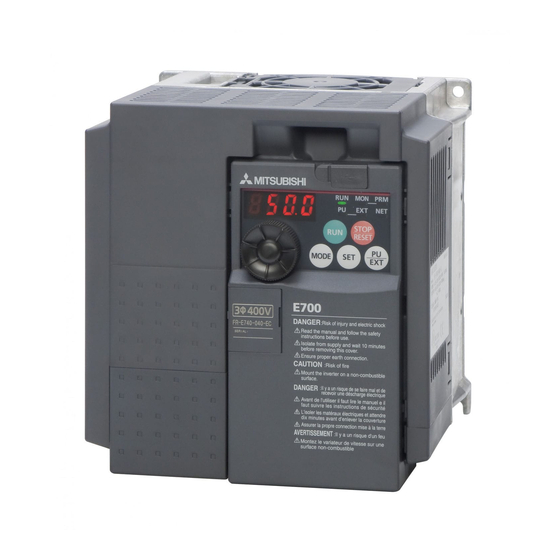
Page 4: Product Checking And Parts Identification
1 PRODUCT CHECKING AND PARTS IDENTIFICATION Unpack the inverter and check the capacity plate on the front cover and the rating plate on the inverter side face to ensure that the product agrees with your order and the inverter is intact. Inverter model - EC E740... - Page 5 PRODUCT CHECKING AND PARTS IDENTIFICATION General Precaution The bus capacitor discharge time is 10 minutes. Before starting wiring or inspection, switch power OFF, wait for more than 10 minutes, and check for residual voltage between terminal P/+ and N/- with a meter etc., to avoid a hazard of electrical shock. Environment Before installation, check that the environment meets following specifications.
-
Page 6: Outline Dimension Drawings
2 OUTLINE DIMENSION DRAWINGS When used with the plug-in option * When the FR-A7NC E kit is mounted, a terminal block protrudes making the depth approx. 2mm greater. (Unit:mm) Standard control circuit terminal model • Three-phase 400V class Inverter Model FR-E740-016 129.1 FR-E740-026... -
Page 7: Wiring
Terminal connection diagram 3 WIRING Terminal connection diagram (1) Standard control circuit terminal model Source logic 1. DC reactor (FR-HEL) Main circuit terminal When connecting a DC reactor, remove the Control circuit terminal jumper across P1 and P/+. Single-phase power input Brake unit *6 A brake transistor is not built-in to the (Option) - Page 8 Terminal connection diagram Safety stop function model Source logic 1. DC reactor (FR-HEL) Main circuit terminal When connecting a DC reactor, remove the Control circuit terminal jumper across P1 and P/+. Single-phase power input Brake unit *6 A brake transistor is not built-in to the (Option) MCCB FR-E720S-008SC and 015SC.
- Page 9 Main circuit terminal specifications Main circuit terminal specifications 3.2.1 Terminal arrangement of the main circuit terminal, power supply and the motor wiring Three-phase 400V class FR-E740-016(SC) to 095(SC) FR-E740-120(SC), 170(SC) Jumper Screw size (M4) Jumper N/- P/+ R/L1 S/L2 T/L3 Screw size (M4) R/L1 S/L2 T/L3 P/+ PR...
- Page 10 Main circuit terminal specifications 3.2.2 Cables and wiring length Cable sizes etc., of the main control circuit terminals and earth (ground) terminals Select the recommended cable size to ensure that a voltage drop will be 2% max. If the wiring distance is long between the inverter and motor, a main circuit cable voltage drop will cause the motor torque to decrease especially at the output of a low frequency.
- Page 11 Main circuit terminal specifications (2) Total wiring length The overall wiring length for connection of a single motor or multiple motors should be within the value in the table below. 200V class Pr. 72 PWM frequency selection Setting or More (carrier frequency) 1 (1kHz) or less 200m...
- Page 12 Control circuit specifications Control circuit specifications Standard control circuit terminal model Control circuit terminal layout Terminal screw size M3: (Terminal A, B, C) M2: (Other than the above) 4 RUN FU SE STF STR Wiring method 1) Strip off the sheath of the wire of the control circuit to wire. Strip off the sheath about the size below.
- Page 13 Control circuit specifications (2) Safety stop function model Control circuit terminal layout Recommend wire size: 0.3mm to 0.75mm S1 S2 Wiring method Use a blade terminal and a wire with a sheath stripped off for the control circuit wiring. For a single wire, strip off the sheath of the wire and apply directly.
- Page 14 Control circuit specifications 3) Insert the wire into a socket. When using a single wire or stranded wire without a blade terminal, push an open/close button all the way down with a flathead screw driver, and insert the wire. Open/close button Flathead screwdriver NOTE When using a stranded wire without a blade terminal, twist enough to avoid short circuit with a nearby terminals or...
-
Page 15: Precautions For Use Of The Inverter
PRECAUTIONS FOR USE OF THE INVERTER 4 PRECAUTIONS FOR USE OF THE INVERTER The FR-E700 series is a highly reliable product, but incorrect peripheral circuit making or operation/handling method may shorten the product life or damage the product. Before starting operation, always recheck the following items. - Page 16 PRECAUTIONS FOR USE OF THE INVERTER (12) Do not apply a voltage higher than the permissible voltage to the inverter I/O signal circuits. Application of a voltage higher than the permissible voltage to the inverter I/O signal circuits or opposite polarity may damage the I/O devices.
-
Page 17: Failsafe Of The System Which Uses The Inverter
FAILSAFE OF THE SYSTEM WHICH USES THE INVERTER FAILSAFE OF THE SYSTEM WHICH USES THE INVERTER When a fault occurs, the inverter trips to output a fault signal. However, a fault output signal may not be output at an inverter fault occurrence when the detection circuit or output circuit fails, etc. -
Page 18: Parameter List
PARAMETER LIST 6 PARAMETER LIST For simple variable-speed operation of the inverter, the initial setting of the parameters may be used. Set the necessary parameters to meet the load and operational specifications. Parameter setting, change and check can be made from the operation panel. - Page 19 PARAMETER LIST Initial Initial Name Setting Range Name Setting Range Value Value Terminal 4 frequency setting Reference value at 0 to 400Hz 50Hz 0 to 200%, 9999 9999 gain frequency acceleration PID control automatic 0 to 400Hz, 9999 9999 Reference value at switchover frequency 0 to 200%, 9999 9999...
- Page 20 PARAMETER LIST Initial Initial Name Setting Range Name Setting Range Value Value RL terminal function selection Output phase loss protection 0, 1 selection RM terminal function selection 0 to 5, 7, 8, 10, Life alarm status display (0 to 15) RH terminal function selection 12, 14 to 16, 18, Inrush current limit circuit life...
- Page 21 PARAMETER LIST Initial Initial Name Setting Range Name Setting Range Value Value Terminal 4 frequency setting Maintenance timer 0 (1 to 9998) 0 to 400Hz (904) bias frequency ∗5 Maintenance timer alarm Terminal 4 frequency setting 0 to 9998, 9999 9999 0 to 300% output set time...
-
Page 22: Troubleshooting
Reset method of protective function 7 TROUBLESHOOTING When a fault occurs in the inverter, the inverter trips and the PU display automatically changes to any of the following fault or alarm indications. If the fault does not correspond to any of the following faults or if you have any other problem, please contact your sales representative. - Page 23 List of fault or alarm indications List of fault or alarm indications Operation Panel Operation Panel Name Name Indication Indication E.ILF ∗1 Input phase loss E--- Faults history E.OLT Stall prevention stop HOLD Operation panel lock E. BE Brake transistor alarm detection LOCD Password locked Output side earth (ground) fault...
- Page 24 CE marking. The authorized representative in the EU The authorized representative in the EU is shown below. Name: Mitsubishi Electric Europe B.V. Address: Gothaer Strasse 8, 40880 Ratingen, Germany Note We declare that this inverter, when equipped with the dedicated EMC filter, conforms with the EMC Directive in industrial environments and affix the CE marking on the inverter.
- Page 25 (2) Low Voltage Directive We have self-confirmed our inverters as products compliant to the Low Voltage Directive (Conforming standard EN 61800- 5-1) and affix the CE marking on the inverters. Outline of instructions ∗ Do not use an earth leakage circuit breaker as an electric shock protector without connecting the equipment to the earth. Connect the equipment to the earth securely.
- Page 26 ∗ Select a UL and cUL certified fuse with Class T fuse equivalent cut-off speed or faster with the appropriate rating for branch circuit protection, or a UL489 molded case circuit breaker (MCCB) in accordance with the table below. FR-E740- (SC)-EC Rated fuse voltage(V) 480V or more...
- Page 27 Appendix 2 Instructions for UL and cUL (Standard to comply with: UL 508C, CSA C22.2 No. 14) 1. General Precaution The bus capacitor discharge time is 10 minutes. Before starting wiring or inspection, switch power off, wait for more than 10 minutes, and check for residual voltage between terminal P/+ and N/- with a meter etc., to avoid a hazard of electrical shock.
- Page 28 REVISIONS *The manual number is given on the bottom left of the back cover. Print Date Revision Manual Number Oct. 2007 IB-0600335ENG-A First edition Addition Dec. 2007 IB-0600335ENG-B • FR-E740-230, 300-EC Addition Oct. 2008 IB-0600335ENG-C • FR-E720S-008 to 110-EC Addition •...
- Page 29 Step 3. Open "index.html" in the opened folder. Step 4. "FR-E700 series documents" HTML opens. Operates according to the steps from "Step 3" of "How to read instruction manuals" • PDF data of the instruction manual are stored in "MANUAL" folder on this CD-ROM.
- Page 30 HEADQUARTERS EUROPEAN REPRESENTATIVES EUROPEAN REPRESENTATIVES EUROPEAN REPRESENTATIVES MITSUBISHI ELECTRIC EUROPE GEVA AUSTRIA MITSUBISHI ELECTRIC IRELAND Beijer Electronics AB SWEDEN EUROPE B.V. Wiener Straße 89 EUROPE B.V.-Irish Branch Box 426 German Branch A-2500 Baden Westgate Business Park S-20123 Malmö Gothaer Straße 8...