Philips AZ7381 Service Manual
Hide thumbs
Also See for AZ7381:
- Service manual (31 pages) ,
- User manual (9 pages) ,
- Instructions for use manual (22 pages)
Table of Contents
Advertisement
Quick Links
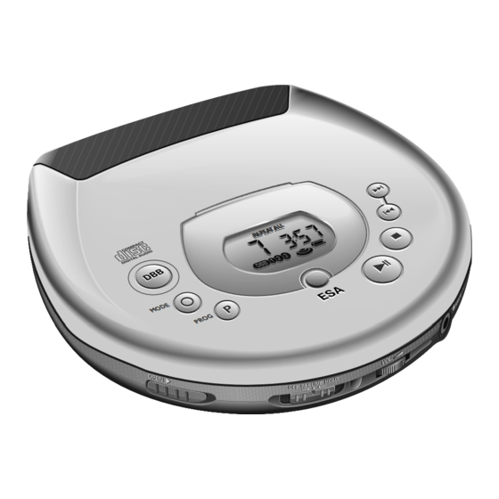
Portable compact disc player
TABLE OF CONTENTS
Technical specification ......................................................1-1
Connections and controls ..................................................1-2
Feature overview ...............................................................1-2
Accessories .......................................................................1-3
Safety warnings .................................................................1-4
Repair positions ............................................................2-1
Service tools..................................................................2-1
Training material ...........................................................2-1
ESD protection equipment ............................................2-1
Handling chip components............................................2-2
Service test program .................................................3-1...3-2
Blockdiagram .....................................................................3-3
Start-up procedure.............................................................3-4
Pinning of ICs ............................................................3-5...3-9
©
Copyright 1997 Philips Consumer Electronics B.V. Eindhoven, The Netherlands
All rights reserved. No part of this publication may be reproduced, stored in a retrieval
system or transmitted, in any form or by any means, electronic, mechanical, photocopying,
or otherwise without the prior permission of Philips.
Published by PW 9813 Service Audio
Printed in The Netherlands
Subject to modification
THIS MANUAL IS VALID FROM FACTORY CHANGE CODE KT02 ONWARDS
Circuit diagrams
Supply/Servodriver part.................................................4-1
Signal processing part...................................................4-2
Membrane assembly 4822 360 10363..........................4-3
Control part ...................................................................4-4
Audio part ......................................................................4-5
Printed circuit board
Copperside view............................................................4-6
Componentside view .....................................................4-7
Exploded view ...........................................................5-1...5-2
Mechanical partslist ...........................................................6-1
Electrical partslist ......................................................6-1...6-3
AZ7381
AZ7386
AZ7382
AZ7387
AZ7383
AZ7481
AZ7384
AZ7482
AZ7385
AZ7483
all versions
MABEL PLATFORM 3A/4A - PB2
CLASS 1
LASER PRODUCT
© 4822 725 26021
CS 46 510
Advertisement
Table of Contents

Related Manuals for Philips AZ7381

Summary of Contents for Philips AZ7381
-
Page 1: Table Of Contents
LASER PRODUCT © Copyright 1997 Philips Consumer Electronics B.V. Eindhoven, The Netherlands All rights reserved. No part of this publication may be reproduced, stored in a retrieval system or transmitted, in any form or by any means, electronic, mechanical, photocopying, or otherwise without the prior permission of Philips. -
Page 2: Technical Specification
TECHNICAL SPECIFICATION General Shock resistance (ESA off) : ≥2.5g Dimensions (WxHxD) : 128x28x136.5mm +X/-X direction : ≥2.5g Weight without batteries : 225g +Y/-Y direction : ≥2.0g +Z/-Z direction Power supply modes Shock resistance by use of car base (ESA off) DC-in socket : 4.5-5.5V : ≥6g... -
Page 3: Connections And Controls
CONNECTIONS AND CONTROLS DISPLAY NEXT 4.5 V DC PREVIOUS PROGRAM STOP PLAY / PAUSE MODE EARPHONE JACK TYPEPLATE VOLUME OPEN HOLD / RESUME DISPLAY....shows the different playing modes, tracks and times § ......skips and searches forward ∞ ......skips and searches backward VOLUME....adjusts the volume level at the headphone socket RESUME/HOLD ..activates the RESUME function and/or HOLD function (locking all buttons) MODE 0 0 ....selects the different playing modes: SHUFFLE™SHUFFLE REPEAT ALL™REPEAT™REPEAT... - Page 4 CS 46 513...
-
Page 5: Safety Warnings
SAFETY WARNINGS © ñ WARNING WAARSCHUWING All ICs and many other semiconductors are susceptible to Alle IC´s en vele andere halfgeleiders zijn gevoelig voor electrostatic discharges (ESD). Careless handling during electrostatische ontladingen (ESD). repair can reduce life drastically. Onzorgvuldig behandelen tijdens reparatie kan de levensduur When repairing, make sure that you are connected with the drastisch doen vermindern. -
Page 6: Service Hints
SERVICE HINTS REPAIR POSITION COPPERSIDE REPAIR POSITION COMPONENTSIDE To get access to the copperside of the To get access to the componentside of the printed circuit board proceed as follows: printed circuit board proceed as follows: 1. Remove the bottom screws (6x) 1. -
Page 7: Handling Chip Components
HANDLING CHIP COMPONENTS CS 46 516... -
Page 8: Service Test Program
SERVICE TEST PROGRAM • To move slide outside hold the “NEXT” button depressed. • To move slide inside hold the “PREV” button depressed. • To accelerate the discmotor clockwise hold the “MODE” button 1. PRELIMINARY SETUP depressed. • To enter the service test program hold the keys “MODE” and •... - Page 9 FLOW CHART To enter service test program hold “MODE” & “STOP”-button PRELIMINARY depressed, while turning POWER ON. Door switch is ignored → CD-door can be opened. SETUP “STOP”-button pressed in any step returns to main menu. Display shows software-version “PLAY” (e.g.
-
Page 10: Blockdiagram
BLOCKDIAGRAM MABEL PBAS2 P TMP87CK20F LCD DRIVER +µP RESET CLOCK GEN. 16bit TIMER & TIMING COUNTER RESET 4.2MHz (FROM DC/DC CONV.) SILD, RAB, SCL, SDA YMLD, YMCLK, YMDATA DISC ZSENSE, SFSY (PWM_IN) KIN1..3, KO1..3 KEYBOARD I/O PORTS TURNTABLE MOTOR DRAM DRAM TRACK SERVO... -
Page 11: Start-Up Procedure
START-UP PROCEDURE Start-up procedure for ext.DC supply, POWER OFF no accu inserted, hold-switch in off pos., (stand-by) ESA/ESP off, resume-mode off, CD-door closed. µP sends command to CD7: PLAY “switch laser on” pressed ? µP sends commands to CD7: “slide servo off” µP switches “focus servo on”... - Page 12 PINNING OF INTEGRATED CIRCUITS TDA1300T – HF-PREAMPLIFIER AND LASER SUPPLY CIRCUIT (part of CD-drive VAM2103) Name Direction Description ––––––––––––––––––––––––––––––––––––––––––––––––––––––––––––––––––––––––––––––––––––––––––––––––––––––––––– HF-preamp → CD7 output of current amplifier 4 HF-preamp → CD7 output of current amplifier 6 HF-preamp → CD7 output of current amplifier 3 HF-preamp →...
- Page 13 SAA7374 – DECODER AND DIGITAL SERVO IC CD7 (low voltage version) Name Direction Description ––––––––––––––––––––––––––––––––––––––––––––––––––––––––––––––––––––––––––––––––––––––––––––––––––––––––––– VSSA1 supply (analog) of CD7 VDDA1 supply (analog) of CD7 HF-preamp → CD7 unipolar current input (central diode signal input) HF-preamp → CD7 unipolar current input (central diode signal input) HF-preamp →...
- Page 14 SM5902AF – COMPRESSION-TYPE ANTI-SHOCK MEMORY CONTROLLER NPC Name Direction Description ––––––––––––––––––––––––––––––––––––––––––––––––––––––––––––––––––––––––––––––––––––––––––––––––––––––––––– supply voltage DRAM SELECT → NPC µP interface extension I/O line 1 DRAM SELECT → NPC µP interface extension I/O line 2 NPC → SOUND CONTROL µP interface extension I/O line 3 NPC →...
- Page 15 MPC17A50VM – 4-CHANNEL H-BRIDGE SERVODRIVER Name Direction Description ––––––––––––––––––––––––––––––––––––––––––––––––––––––––––––––––––––––––––––––––––––––––––––––––––––––––––– CGND ground (control part) power supply input (control part) CD7 → servo driver ERR2 error level input (slide error signal) → servo driver filter capacitor connection in ABS amp circuit section →...
- Page 16 MPC1825A – DC/DC CONVERTER AND BATTERY CHARGER Name Direction Description ––––––––––––––––––––––––––––––––––––––––––––––––––––––––––––––––––––––––––––––––––––––––––––––––––––––––––– DCIN DC power supply input → DC/DC converter detection input of charge current (battery charger block) → DC/DC converter connection of error amplifier feedback resistor (battery charger block) → DC/DC converter INM2 inverting input of error amplifier (battery charger block) DC/DC converter →...
-
Page 17: Supply/Servodriver Part
1250 B 2 1950 I20 1951 L21 2250 B 1 SUPPLY/SERVODRIVER PART 2252 F 2 2253 F 2 2254 G 2 2255 H 2 2257 F 6 2258 H 6 2259 H 7 2260 J 6 6250 5.0V 4.6V 2261 J 7 2262 H 7 SB10-05PCP 2263 E 8... -
Page 18: Signal Processing Part
1800 H 1 2808 L 4 2811 L 4 2814 H 7 2817 F 8 2820 G 8 2823 J 9 2826 D 8 2830 D14 2833 H17 2836 I20 2853L I21 3811 K 4 3814 L 5 3819 A 8 3822 C 8 3825 F 8 3828 G 8... -
Page 19: Membrane Assembly 4822 360 10363
MEMBRANE ASSEMBLY 4822 360 10363 1001 1002 1003 SHUFFLE REPEATALL PROG SCAN RESUME 1006 1005 1004 1007 1008 KIN1 KIN2 KIN3 TO/FROM CONTROL PART / 1401 CS 46 528... -
Page 20: Control Part
1401 A 6 1418 A 2 CONTROL PART 1430 A 5 2404 G 2 2405 G 3 2407 H11 2410 F 6 SERVICE TEST 2411 E 7 2412X E 7 Resume/Hold from/to membrane assembly 1430 2413 E 5 1401 COM 3 ESE11SH1 3376 H12 1418... -
Page 21: Audio Part
1350 F15 2303 D 3 2313 D 6 2314 E 6 2316 E 7 AUDIO PART 2317 D 7 2318 E 7 2319 D 7 2320 G 6 2321 D 8 2322 E 8 2323 E 6 2324 H 8 2325 G 6 2349 B13 2350 E 9... -
Page 22: Copperside View
COPPERSIDE VIEW 1401 A 2 2836 D 2 3432 B 2 2250 A 2 2837 B 1 3809 B 1 2252 A 3 2953 D 1 3810 B 1 2253 A 3 2954 D 1 3811 B 1 2254 A 3 2955 D 1 3812 B 1 2255 A 3... -
Page 23: Componentside View
COMPONENTSIDE VIEW 1250 A 3 3853L D 2 1350 E 4 3857 D 2 1418 E 2 3859 D 1 1250 1430 A 4 3950 C 1 2264 1800 D 1 3951 C 1 1950 A 4 3952 D 1 1951 D 2 3953 D 1 2260 B 4... - Page 24 EXPLODED VIEW CD-DOOR (2x) (6x Plastite 1,4x2,5) EV CD door Mabel xA, 191297 CS 46 533...
-
Page 25: Exploded View
EXPLODED VIEW open CD - drive VAM2103 (3x) Door switch Volume (6x Plastite Torx 1,7x9) (2x) EV body Mabel xA/PB2, 080498 CS 46 534... -
Page 26: Mechanical Partslist
MECHANICAL PARTSLIST ELECTRICAL PARTSLIST 401 4822 410 11567 BUTTON-SET-ESA-2-LAC-PRINTED MISCELLANEOUS 402 4822 360 10363 MEMBRANE-LCD-2 ASSY ––––––––––––––––––––––––––––––––––––––––––––––––––––– 403 4822 443 10893 SERV.ASSY CD-DOOR (2) PH 1250 4822 265 10626 SOCKET, EXT. SUPPLY AZ738x only 403 4822 443 10894 SERV.ASSY CD DOOR (2) MVX 1350 4822 265 11247 HEADPHONE SOCKET... - Page 27 CAPACITORS RESISTORS ––––––––––––––––––––––––––––––––––––––––––––––––––––– ––––––––––––––––––––––––––––––––––––––––––––––––––––– 2404 © 5322 126 11578 3256 © 4822 117 12889 270kΩ 1% 0,0625W 2405 © 5322 126 11578 3257 © 4822 117 12891 220kΩ 1% 0,0625W 2407 © 4822 126 14305 100nF 3258 © 4822 117 12884 100kΩ...
- Page 28 RESISTORS COILS ––––––––––––––––––––––––––––––––––––––––––––––––––––– ––––––––––––––––––––––––––––––––––––––––––––––––––––– 3424 © 4822 117 12896 47kΩ 5% 0,0625W 5251 © 4822 157 70753 100µH 10% LQH4N 3425 © 4822 117 12887 1MΩ 5% 0,0625W 5252 © 4822 146 10663 TRANSFORMER 6RG (DC/DC) 3430 © 4822 117 12913 1kΩ...