Linksys SFE2000 Administration Manual
Hide thumbs
Also See for SFE2000:
- Reference manual (270 pages) ,
- Quick installation manual (28 pages) ,
- Product data (4 pages)
Table of Contents
Advertisement
Quick Links
Advertisement
Table of Contents

Related Manuals for Linksys SFE2000


Summary of Contents for Linksys SFE2000
- Page 1 Release 1.0 Linksys SFE2000/SFE2000P Fast Ethernet Switch Administration Guide...
- Page 2 Specifications are subject to change without notice. Linksys, the Cisco Systems logo, the Linksys Logo, and the Linksys One logo are registered trademarks of Cisco Systems, Inc. All other trademarks mentioned in this document are the property of their respective owners.
-
Page 3: Table Of Contents
Linksys One Ready Communications Solution Contents Chapter 1: Introduction - - - - - - - - - - - - - - - - - - - - - - - - -1 What’s in this User Guide? Chapter 2: Getting to Know the Switch... - Page 4 Viewing Online Help Appendix A: Linksys Contact Information - - - - - - - - - - - - - - - 32 Appendix B: Customer Site Survey - - - - - - - - - - - - - - - - - - 34...
-
Page 5: Chapter 1: Introduction
If your Ethernet switch is part of a Linksys One system, the easiest way to manage it is with the Linksys One Portal — available only on the Linksys One Services Router. Refer to the Linksys One Customer Premises Equipment Administration Guide for more details on the Linksys One Portal. - Page 6 Linksys One Ready Communications Solution This user guide contains the following chapters: Chapter 1, "Introduction" This chapter describes the Ethernet switch applications and provides an overview of the content of this administration guide. Chapter 2, "Getting to Know the Switch"...
-
Page 7: Chapter 2: Getting To Know The Switch
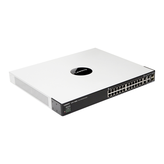
Getting to Know the Switch Overview The SFE2000 and SFE2000P models are 24-port, layer-2 Ethernet switches that expand the System Status LEDs. Four LEDs indicate the status capability of the Linksys system. These two versions are functionally identical except the... -
Page 8: Lan Port Leds
(Activity) LEDs flash to indicate that the Ethernet switch is actively sending or receiving data over that port. • On the SFE2000, a green Link LED indicates that the port is linked to a 10/100Mbps device. • On the SFE2000P, a green Link LED indicates that PoE is active on that port. -
Page 9: Stack Id Leds
Linksys One Ready Communications Solution Stack ID LEDs Stack ID A green Stack ID LED indicates that this Switch is stacked and the corresponding number indicates its stack ID. Range is 1 to 8. Reset Switch The Ethernet switch can be reset by inserting a pin or paper clip into the RESET opening. If the reset switch is held for 10 seconds or longer, the Ethernet switch will be reset to its default settings. -
Page 10: Uplink Ports
1000Mbps. Console Port. The Console port is where you can Use the Linksys MGBT1, MGBSX1, or MGBLH1 mini-GBIC modules connect a serial cable to a PC’s serial port for with the Switch. The MGBSX1 and the MGBLH1 require fiber cabling ”Console... -
Page 11: Power Port
An optional Redundant Power Supply (RPS) is connected to the RPS port. An RPS enhances the reliability of the Ethernet switch and it can keep the unit running if a power failure occurs. Only use a Linksys RPS1000 Redundant Power Supply unit and a proper RPS cable (RPSCBL1) with the Ethernet switch. -
Page 12: Chapter 3: Connecting The Switch
Linksys One Ready Communications Solution Connecting the Switch Overview This chapter will explain how to connect network devices to the Ethernet switch. For an example of a possible network configuration, see the application diagrams shown below. Before You Install the Switch... -
Page 13: Placement Options
Linksys One Ready Communications Solution Placement Options Before connecting cables to the Ethernet switch, first you will physically install the Ethernet switch. Either set the Ethernet switch on its four rubber feet for desktop placement, mount it in a standard-sized, 19-inch wide for rack-mount placement, or mount it on a wall with the wall-mount brackets provided. -
Page 14: Wall-Mount Placement
Linksys One Ready Communications Solution 4. Repeat steps 2 through 3 for the other side of the Ethernet switch. 5. Attach the Ethernet switch to the rack using the supplied screws. Wall-Mount Placement 1. On one of the side corners, remove the four front screws on of the Ethernet switch. Retain the screws for re-installation. - Page 15 Linksys One Ready Communications Solution 3. Repeat steps 2 and 3 to connect additional devices. 4. If you are using the mini-GBIC port, then insert the mini-GBIC module to the mini-GBIC port. For detailed instructions, refer to the documentation supplied with the mini-GBIC module.
-
Page 16: Stacking Multiple Switches
The master and backup master are assigned unit IDs of 1 and 2. The Stack Master • Stack cannot combine Linksys SFE2000 and provides a single point of control and management as well as a single interface in which to SGE2000 family Ethernet switches. -
Page 17: Connecting Cabling For Stacking
Linksys One Ready Communications Solution By default, the Ethernet switch is in stacking mode. Using the console interface or the web interface, you can change the mode to standalone mode. TIP: Power the Ethernet switches in the order that you want them in the Stack ID. -
Page 18: Chapter 4: Console Configuration
3. Select HyperTerminal from the options listed in this menu. 4. On the Connection Description screen, enter a name for this connection. In the example, the name of connection is Linksys One. 5. Select an icon for the application. Then, click the OK button. - Page 19 Linksys One Ready Communications Solution 6. On the Connect To screen, select a port to communicate with the Ethernet switch. 7. Set the serial port settings as follows: • Bits per second: 115200 • Data bits: 8 • Parity: None •...
-
Page 20: Connecting To The Switch Using Telnet Or Ssh
Linksys One Ready Communications Solution Connecting to the Switch using Telnet or SSH If you know the IP address of your Ethernet switch (obtained from your DHCP server or the console interface), you can connect to the switch through a Telnet session. -
Page 21: Switch Main Menu
Linksys One Ready Communications Solution Switch Main Menu The System Main Menu screen displays these choices: System Configuration Menu Port Status Port Configuration System Mode (Layer 2 / Layer 3) Selection Help System Configuration Menu On the System Configuration Menu screen, you have these choices:... - Page 22 Linksys One Ready Communications Solution Versions Use the Versions screen to display the boot, software, and hardware firmware versions of the Ethernet switch. In stacking mode, This information is displayed for the stack master. General System Information Use the General System Information screen to display the description, System Up Time, System MAC Address, System Contact, System Name, and System Location of the Ethernet switch.
- Page 23 Linksys One Ready Communications Solution Serial Port Configuration Use the Serial Port Configuration screen to display the baud rate of the Ethernet switch. To change the baud rate of the serial port: a. Select Edit to make changes. b. When your changes are complete, press the Esc key to return to the Action menu.
- Page 24 Linksys One Ready Communications Solution SSH Configuration Use the SSH Configuration screen to configure and display SSH settings. SSH Server Configuration: Use the SSH Server Configuration screen to enable or disable the SSH server, and to configure the port over which the SSH session is enabled.
- Page 25 NOTE: The default user is “admin” with no password. There is also a special user defined by default for internal use by the Linksys system (l1_admin). For support reasons, it is recommended that you not delete this user. To change User & Password settings: a.
- Page 26 Linksys One Ready Communications Solution Security Settings The Security Settings screen enables you to configure security settings on the Ethernet switch, as well as generate and display the certificate. Use the SSL Certificate Generation screen to specify a device-generated certificate.
- Page 27 Linksys One Ready Communications Solution Country Name Specifies the country name. (Range: 2 to 2) Validity Term Specifies number of days certification is valid. (Range: 30 to 3650) To change SSL Certificate Generation settings: a. Select Edit to make changes.
- Page 28 Linksys One Ready Communications Solution IP Configuration The IP Configuration screen displays these choices: the IP Address Settings, HTTP, HTTPS Configuration, and Network Configuration of the Ethernet switch. IP Address Configuration (Layer 2) The IP information of the Ethernet switch is displayed here.
- Page 29 Linksys One Ready Communications Solution To change IP address configuration settings: a. Select Edit to make changes. b. When your changes are complete, press the Esc key to return to the Action menu. c. Select Save to save your changes.
- Page 30 Linksys One Ready Communications Solution c. Select Save to save your changes. Network Configuration The Network Configuration screen offers a choice of two tests, Ping and TraceRoute. Ping The Ping screen displays the IP address of the location you want to contact.
- Page 31 Linksys One Ready Communications Solution Select Edit to make changes. When your changes are complete, press the Esc key to return to the Action menu, and select Save to save your changes. File Management The File Management screen allows you to upload or download files, such as the startup configuration, boot, or image file, using a TFTP server.
- Page 32 Settings and press the Enter key. You will be asked if you want to continue. Press the y key to restore the default settings, or press the n key to cancel. NOTE: Restoring default settings from the console, web, or Linksys One portal interfaces resets all values except stacking configuration (stacking mode, stacking ports, and auto-numbering settings are NOT reset).
- Page 33 The System Mode Selection screen lets you specify whether the Ethernet switch is operating in Layer 2 or Layer 3 mode. You can also configure stacking mode from this screen. IMPORTANT: If the Ethernet switch is being used as part of a Linksys One system, it must operate as a Layer 2 switch.
- Page 34 Linksys One Ready Communications Solution 3. To edit these modes, select Edit to make changes. When your changes are complete, press the Esc key to return to the Action menu. 4. Select Save to save your changes. 5. Reboot the Ethernet switch. Your new settings will take effect after reboot.
-
Page 35: Chapter 5: Web Utility Configuration
Console configuration or the Linksys One Administrator screen. If your Ethernet switch is part of a Linksys One system, the easiest way to manage it is with the Linksys One Portal — available only on the Linksys One Services Router. Refer to the Customer Premises Equipment Administration Guide for more details on the Linksys One Portal. -
Page 36: Appendix A: Linksys Contact Information
Linksys Contact Information Need to contact Linksys? Visit us online for information on the latest products and updates to your existing products at: http://www.linksys.com/international If you experience problems with any Linksys product, you can e-mail us at: In Europe E-mail Address Austria support.at@linksys.com... - Page 37 Linksys One Ready Communications Solution In Europe E-mail Address Russia support.ru@linksys.com Spain support.es@linksys.com Sweden support.se@linksys.com Switzerland support.ch@linksys.com United Kingdom support.uk@linksys.com Outside of Europe E-mail Address Asia Pacific asiasupport@linksys.com (English only) Latin America support.portuguese@linksys.com or support.spanish@linksys.com Middle East & Africa support.mea@linksys.com (English only) South Africa support.ze@linksys.com (English only)
-
Page 38: Appendix B: Customer Site Survey
Linksys One Ready Communications Solution Customer Site Survey Use this Customer Site Survey to gather customer contact information and other information about the customer site that will be needed for the implementation and installation of the Linksys Solution. Customer Site Survey... - Page 39 Linksys One Ready Communications Solution Customer Site Survey (Continued) Pager # E-mail After Hours Contact Phone Number If this site is not customer-owned, who is the owner and maintainer of the site? Is this Site owned and maintained by the customer? Is this a manned site? Specify the hours of operation (for example, Monday through Friday, 8am to 5pm, Saturday 9 am to 12 Noon).
- Page 40 Linksys One Ready Communications Solution Customer Site Survey (Continued) Specify any special security/safety procedures, such as the need for safety glasses, safety shoes, and the location(s) of hardhat areas. Security/Safety Procedures Specify the name and phone number of the site coordinator responsible for ensuring that the site is adequately prepared for the installation of the Cisco equipment.
-
Page 41: Appendix C: Limited Warranty
Linksys warrants to the original end user purchaser of the Linksys Product (“You”) that for a period of five (5) years for the Linksys Product’s Hardware and for a period of one (1) year for the Linksys Product’s fan and power supply (the “Warranty Period”), your Linksys Product will be substantially free of defects in materials and workmanship under normal use. - Page 42 Linksys One Ready Communications Solution (INCLUDING NEGLIGENCE), ARISING OUT OF OR RELATED TO THE USE OF OR INABILITY TO USE THE PRODUCT (INCLUDING ANY SOFTWARE), LINKSYS SFE2000 OR SFE2000P FAST ETHERNET SWITCH EVEN IF LINKSYS HAS BEEN ADVISED OF THE POSSIBILITY OF SUCH DAMAGES.
-
Page 43: Appendix D: Federal Communication Commission Interference Statement
Linksys One Ready Communications Solution Federal Communication Commission Interference Statement This Equipment has been tested and found to comply with the limits for a Class A digital device, pursuant to part 15 of the FCC Rules. These limits are designed to provide reasonable protection against harmful interference when the equipment is operated in a commercial environment. -
Page 44: Appendix E: Specifications
Linksys One Ready Communications Solution Specifications Models • SFE2000 — 24-port 10/100 Ethernet switch • SFE2000P — 24-port 10/100 Ethernet switch with PoE Standards 802.3 10BASE-T Ethernet, 802.3u 100BASE-TX Fast Ethernet, 802.3ab 1000BASE-T Gigabit Ethernet, 802.3z Gigabit Ethernet, 802.3x Flow Control, 802.3ad LACP,802.3af POE, 802.1d STP, 802.1Q/p VLAN,... - Page 45 Linksys One Ready Communications Solution Layer 2 • MAC table size - 8K options • Number of VLANs - 256 active VLANs (4096 range) • VLAN - Port-based and 802.1Q Tag-based VLANs - Protocol-based VLAN, Management VLAN - Private VLAN Edge (PVE) - GARP VLAN Registration Protocol (GVRP) •...
- Page 46 Linksys One Ready Communications Solution Other • Traceroute Management • Single IP Management • Secure Socket Layer (SSL) security for Web UI • Secure Shell (SSH) • RADIUS • Port Mirroring • TFTP upgrade • DHCP Client • BootP • SNTP •...
- Page 47 Linksys One Ready Communications Solution DOS Attack prevention prevention Spanning IEEE 802.1D Spanning Tree, IEEE 802.1w Rapid Spanning Tree, IEEE Tree 802.1s Multiple Spanning Tree, Fast Linkover IGMP IGMP (v1/v2) snooping limits bandwidth-intensive video traffic to only Snooping the requestors. Support 256 multicast groups.
- Page 48 440 x 375 x 44 mm, 17.32 x 14.70 x 1.73 inch (W x D x H) Unit Weight • SFE2000 — 4.39kg, 9.68 lbs • SFE2000P — 4.94kg, 10.89 lbs Power • SFE2000 — 100-240VAC, 50-60 Hz, 0.54A MAX • SFE2000P — 100-240VAC, 50-60 Hz, 2.25A MAX Appendix E: Specifications...
- Page 49 Linksys One Ready Communications Solution Appendix E: Specifications...
- Page 50 ©2007 Cisco Systems, Inc. All rights reserved. Linksys is a registered trademark and the Linksys One logo is a trademark of Cisco Systems, Inc. Release 1.0...