Stuart Turner Monsoon U1.5 bar Twin Installation, Operation & Maintenance Instructions Manual
Hide thumbs
Also See for Monsoon U1.5 bar Twin:
- Installation instructions manual (24 pages) ,
- Installation, operation & maintenance instructions manual (28 pages)
Table of Contents
Advertisement
MONSOON
Installation, Operation & Maintenance
Instructions
Please leave this instruction booklet with the home owner as it contains important
warranty, maintenance and safety information.
Read this manual carefully before commencing installation.
This manual covers the following products:
Monsoon U1.5 bar Twin
Pt. No. 46505
Pt. No. 46505 EXP
Monsoon U2.0 bar Twin
Pt. No. 46480
Pt. No. 46480 EXP
Monsoon U3.0 bar Twin
Pt. No. 46410
Pt. No. 46410 EXP
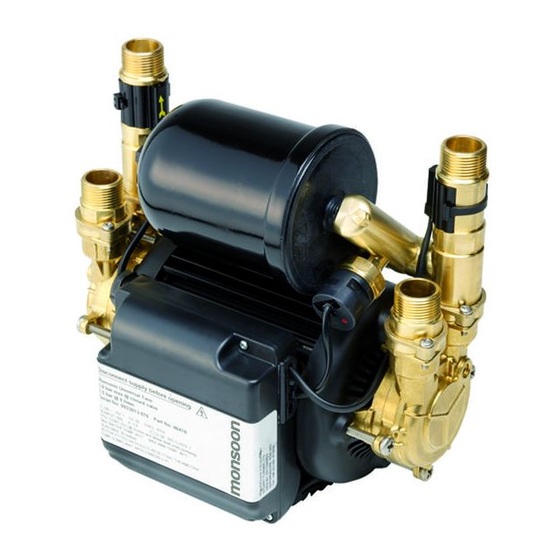
Please note images are representative only and may not portray
Pt. No. 46505 ROI
Pt. No. 46480 ROI
Pt. No. 46410 ROI
FOR POSITIVE OR NEGATIVE HEAD APPLICATIONS
Monsoon U4.0 bar Twin
Pt. No. 46411
Pt. No. 46411 EXP
Monsoon U4.5 bar Twin
Pt. No. 46412
Pt. No. 46412 EXP
your model
Pt No. 46411 ROI
Pt No. 46412 ROI
Advertisement
Table of Contents

Related Manuals for Stuart Turner Monsoon U1.5 bar Twin


Summary of Contents for Stuart Turner Monsoon U1.5 bar Twin
- Page 1 Please leave this instruction booklet with the home owner as it contains important warranty, maintenance and safety information. Read this manual carefully before commencing installation. This manual covers the following products: Monsoon U1.5 bar Twin Monsoon U4.0 bar Twin Pt. No. 46505 Pt. No. 46505 ROI Pt.
-
Page 2: Table Of Contents
CONTENTS PRODUCT DESCRIPTION ................. 1 2 WARNINGS ....................2 3 CHECKLIST ....................4 4 REGIONAL SUITABILITY .................. 5 5 PRE-INSTALLATION CHECK ................6 6 IMPORTANT FACTS - READ BEFORE COMMENCING PUMP INSTALLATION..7 7 LOCATION - G ENERAL ................... 9 8 PUMP CONNECTIONS ................... -
Page 3: Product Description
PRODUC T DESCRIPTION Product Description Electric motor driven twin ended peripheral pumps complete with an automatic control system, consisting of flow switches, pressure switch and pressure vessel and electronic controls. Application Monsoon Universal pumps are suitable for positive or negative head installation conditions. -
Page 4: Warnings
WARNINGS • This pump set must not be used for any other application without the written consent of Stuart Turner Limited and in particular, must not be connected directly to the mains water supply. • This appliance can be used by children aged from 8 years and... - Page 5 • This appliance must be earthed via the supply cord, which must be correctly connected to the earth point located in the terminal box. • The supply cord and internal wiring within the terminal box are routed and secured to ensure compliance with the electrical standard EN 60335-1.
-
Page 6: Checklist
CHECKLIS T IMPORTANT: With the pump removed from its packaging check for any damage prior to installation. If any damage is found contact Stuart Turner Ltd within 24 hours of receipt. Figure 1 Item Description Pump Hose & integral washer Tank &... -
Page 7: Regional Suitability
REGIONAL SUITABILITY Before commencing installation, ensure the product you have purchased is correct for your region, to avoid invalidating the warranty. Check the part number: Example: UK product Pt. No. 46416 ROI product Pt. No. 46416 ROI Export product Pt. No. 46416 EXP This installation guide refers to UK pipework and pumps supplied with hoses suitable for 22 mm pipework. -
Page 8: Pre-Installation Check
PRE-INSTALLATION CHECK Pressure vessel Figure 2 Note: This image is for reference only. The pressure vessel (Figure 2) is factory fitted to the pump assembly. To eliminate any risk that the vessel has lost its assembly torque and sealing ability during transit, it must be checked prior to installation and should be hand tight. -
Page 9: Important Facts - Read Before Commencing Pump Installation
IMPORTANT FACTS - READ BEFORE COMMENCIN G PUMP INSTALLATION Water Storage Capacity The hot and cold water storage capacity must be sufficient to meet the flow rates required by the pumped equipment and any other water using fittings and appliances, which may be operated simultaneously. Ensure the pump is primed as described in the priming section before starting, damage to the shaft seal will result otherwise. - Page 10 Plumbing Installation Regulations The plumbing installation must comply with the current water and building regulations. The plumbing installation must be installed by a qualified person. Pressure Vessel Pressure vessel is charged at the factory see Section 11.2- Maintenance for details.
-
Page 11: Location - General
Direction of flow: Ensure the water flow is in the direction of the arrow that is marked on the flow switch reed clamp (vertically upwards). • Flexible hoses: Only use the Stuart Turner hose set supplied with the pump. • Isolating valves: Separate system isolating valves (non... - Page 12 Preferred Pump Location The pump must, for optimum performance, be sited as close as possible to and never more than 4 metres from the HOT WATER cylinder. The pump should always be sited BELOW the HOT WATER take-off from the cylinder. The pump location is also dependent on limitations of the static inlet and outlet heads of the installation.
- Page 13 Non-Preferred Pump Location If it is necessary to position the pump above the secondary tapping on the hot cylinder it is fed by, the risk of introducing air will be increased. To avoid this risk one of the two following solutions must be adopted: a.
- Page 14 Cold Water Connection The cold water supply: Must be a DEDICATED AIR FREE supply via a tank connector, and must be positioned at a slightly lower level (25 mm minimum) than the feed pipe to the hot water cylinder. Ensure that the pipework size from the cold water tank is 22 mm minimum. Do not connect to the mains.
-
Page 15: Pump Connections
PUMP CONNECTIONS • Do not use stainless steel, chrome or nickel plated pipe with the flexible hose push-in plumbing connections. • Do not introduce solder flux into the joint or surrounding area as connectors will be attacked and will fail. •... - Page 16 Hose to Pump The pump inlet and outlet ports have factory assembled fittings which are specifically designed for connection to the G ¾ F running nuts on the flexible hoses. The hose end is fitted with a rubber sealing washer which is held captive within the nut assembly.
- Page 17 Hose to Pipework The hoses are fitted with plastic push-in connectors, which must only be connected to the following: 22 mm dia. pipework in the UK. 21 mm dia pipework in the ROI. 1. Ensure the pipe is free from all score marks and deformities in the area of the insertion depth (Figure 8) and cut the pipe square, removing all burrs and sharp edges to prevent damage to the sealing ‘O’-ring.
- Page 18 3. Check in the mouth of the fitting that the ‘O’-ring, nylon washer and collet are in position as shown in Figure 9. Collet Washer O-ring Flexible hose Pipe stop Figure 9 4. Push pipe firmly into the fitting, until pencil mark is level with the top of the collet and the pipe stop resistance is felt.
- Page 19 22mm compression to G ¾ M G ¾ F x 22mm elbow tap connector G ¾ F flexible hose (supplied) Fibre washer 22mm copper pipe 22mm compression to G ¾ M 22mm elbow G ¾ F flexible hose (supplied) 22mm copper pipe G ¾...
-
Page 20: Electrical Installation
ELECTRIC AL INSTALLATION • Regulations: The electrical installation must be carried out in accordance with the current national electrical regulations and installed by a qualified person. • Safety: In the interests of electrical safety a 30 mA residual current device (R.C.D. not supplied) should be installed in the supply circuit. - Page 21 • Connections: The pump must be permanently connected to the fixed wiring of the mains supply using the factory fitted supply cord, via a double pole switched fused spur off the ring main and NOT connected to the boiler or the immersion heater circuits.
- Page 22 Wiring of Connection Unit WARNING: This appliance must be earthed. The wires in the mains lead (supply cord) are coloured in accordance with the following code: • Green and Yellow: Earth • Blue: Neutral • Brown: Live As the colours of the wires in the mains lead of this appliance may not correspond with the coloured markings identifying the terminals in your connection unit proceed as follows: •...
- Page 23 Wiring Diagram MAIN WINDING BLUE THERMOTRIP CAPACITOR START WINDING BLUE N 230 VAC/1PH/50Hz BROWN SUPPLY GREEN / YELLOW S2 S3 S3 S2 FLOWSWITCH REED (S3) FLOWSWITCH REED (S2) PRESSURE SWITCH (S1) Figure 12...
- Page 24 If the supply cord is to be changed or is damaged, it must be replaced with a special cord assembly available from Stuart Turner or one of their approved repairers. On disassembly note the cord retention and routing system. Re-assemble to the same pattern.
-
Page 25: Commissioning
COMMISSION IN G System Flushing: This pump incorporates push-in connectors and plastic components that must not come into contact with solder flux, acid-based descalents or aggressive cleaning agents. The pipework system should be flushed out prior to the pump being connected to ensure any contaminants/chemical residues and foreign bodies are removed from elsewhere in the system. - Page 26 Carefully check pump and pipework for leaks whilst pump running and stationary before leaving the installation unattended. For Further Technical Support: Phone the Stuart Turner TechAssist team on +44 (0) 800 31 969 80. Our staff are trained to help and advise you over the phone.
-
Page 27: Maint Enance
MAINTENAN CE Turn off water supplies to the pump and release pressure by opening water outlets before attempting maintenance 11.1 Inlet Strainer The inlet strainers may require periodical cleaning. The frequency of this operation is dependent upon installation conditions. The strainer is located in the inlet assembly of the pump casing and is removed as follows: Isolate pump electrically. - Page 28 11.2 Pressure Vessel Should the need arise for the vessel to have its air charge checked or replenished, it should be carried out as follows: Isolate pump electrically. Isolate hot and cold water supplies via the integral pump isolating valve located in the flexible hoses (see Section 8.1).
- Page 29 11.3 Water Scale As water is heated scale deposits are released in areas of hard water, scale can cause the mechanical seal to stick if left without use for long periods. The pump must be run for at least 5 minutes every four weeks to “exercise” all working parts. Run on cool water.
-
Page 30: Technical Specification
TECHNICAL SPECIFIC ATION Pump Model U1.5 bar U2.0bar U3.0 bar U4.0 bar U4.5 bar Twin Twin Twin Twin Twin 46505 46480 46410 46411 46412 General Warranty 5 years WRAS approval 1906076 Approvals WRAS, CE Features Pump type Peripheral Mechanical seal EPDM/PTFE/AI. - Page 31 9.2 Kg 11.1 Kg 11.6 Kg fittings ) Stuart Turner reserve the right to amend the specification in line with its policy of continuous development of its products. Note: For information on other voltages/frequencies which are not shown, consult TechAssist on +44 (0) 800 31 969 80.
-
Page 32: Trouble Shooting Guide
Check fuse (see fuse section). Check circuit breaker is set. Check wiring connections. Pump Jammed. If motor ‘Buzzes’ switch off power and contact Stuart Turner. Damaged pressure Turn off power. switch. Release system water pressure. Turn on power, pump should start. If NOT contact Stuart Turner. - Page 33 P.C.B. closed circuit in either the flow switch reed, Pump cycles pressure switch or P.C.B. in the terminal (hunts) on/off box. Contact Stuart Turner. frequently Jammed flow Remove outlet hoses and check that flow switch. switch sits in lowest position. Check float for free movement.
- Page 34 9. To restart the pump, the power supply should be first isolated for a period of at least 10 seconds before switching on again. If the pump fails to operate normally after three attempts to re-start, then please consult Stuart Turner TechAssist +44 (0) 800 31 969 80.
- Page 35 If this does not happen, this indicates a possible fault with the reed switch or the P.C.B which is located within the terminal box. These should be checked electrically. Consult Stuart Turner for further instructions. Body Reed...
- Page 36 13.4 Fault Finding The PCB is also fitted with a “power on” indicator light. This will remain illuminated when mains power is supplied to the board. The indicator light is located on the PCB within the terminal box. This operation should only be carried out by a competent person. To view the light the following procedure must be followed: Isolate the mains electrical power supply from the pump.
-
Page 37: The Monsoon Warranty - 5 Yea Rs
Proof of purchase should accompany the returned unit to avoid delay in investigation and dealing with your claim. You should obtain appropriate insurance cover for any loss or damage which is not covered by Stuart Turner Ltd in this provision. Please record here for your reference: TYPE NO. -
Page 38: Declaration Of Conformity
DECLARATION OF CONFORM ITY Issue No. 5020 / 01-01 Pt. No. 21156...