Table of Contents
Advertisement
Quick Links
User Manual
Thank you for purchasing our product. If there are any
questions, or requests, do not hesitate to contact the
dealer.
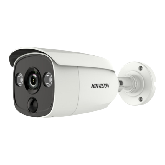
This manual applies to the models below:
Type
Type I
Camera
Type II
Camera
This manual may contain several technical incorrect
places or printing errors, and the content is subject to
change without notice. The updates will be added to
the new version of this manual. We will readily improve
or update the products or procedures described in the
manual.
D0T PIR Series Bullet
TURBO HD
User Manual
Model
DS-2CE11D0T-PIRL
DS-2CE11D0T-PIRLP
DS-2CE12D0T-PIRL
01000020200821
Camera
Advertisement
Table of Contents

Related Manuals for HIKVISION DS-2CE11D0T-PIRLP


Summary of Contents for HIKVISION DS-2CE11D0T-PIRLP
- Page 1 This manual applies to the models below: Type Model DS-2CE11D0T-PIRL Type I Camera DS-2CE11D0T-PIRLP Type II DS-2CE12D0T-PIRL Camera This manual may contain several technical incorrect places or printing errors, and the content is subject to change without notice. The updates will be added to the new version of this manual.
-
Page 2: Regulatory Information
Regulatory Information FCC Information Please take attention that changes or modification not expressly approved by the party responsible for compliance could void the user’s authority to operate the equipment. FCC compliance: This equipment has been tested and found to comply with the limits for a Class A digital device, pursuant to part 15 of the FCC Rules. - Page 3 Safety Instruction These instructions are intended to ensure that user can use the product correctly to avoid danger or property loss. The precaution measure is divided into “Warnings” and “Cautions”. Warnings: Serious injury or death may occur if any of the warnings are neglected.
- Page 4 Keep the camera away from liquid while in use for non-water-proof device. While in delivery, the camera shall be packed in its original packing, or packing of the same texture. Mark Description Table 0-1 Mark Description Mark Description DC Voltage...
-
Page 5: Installation
1 Introduction 1.1 Product Features The main features are as follows: High performance CMOS sensor IR cut filter with auto switch OSD menu with configurable parameters Auto white balance internal synchronization SMART IR mode Visible alarm ... - Page 6 2.1 Installation of Type I Camera 2.1.1 Ceiling/Wall Mounting without Junction Box Steps: 1. Paste the drill template (supplied) to the place where you want to install the camera. 2. Drill the screw holes and the cable hole (optional) in the ceiling/wall according to the drill template.
- Page 7 1). Loosen the P screw to adjust the pan position [0° to 360°]. Tighten the screw after completing the adjustment. 2). Loosen the T screw to adjust the tilt position [0° to 180°]. Tighten the screw after completing the adjustment. 3).
- Page 8 7. Route the cables through the bottom cable hole, or the side cable hole of the junction box. 8. Combine the junction box cover with its body. Figure 2-7 Fix the Junction Box Cover back to its Body 9. Repeat the step 5 and 6 of 2.1.1 Ceiling/Wall Mounting without Junction Box to complete the installation.
-
Page 9: Ceiling/Wall Mounting With Junction Box
6. Power on the camera to check whether the image on the monitor is gotten from the optimum angle. If not, adjust the surveillance angle. Pan Position [0° to 360°] Tilt Position [0° to 180°] Rotation Position [0° to 360°] Figure 2-10 3-Axis Adjustment Loosen the No.1 adjusting screw to adjust the pan position [0°... -
Page 10: Menu Description
6. Route the cables through the bottom cable hole, or the side cable hole of the junction box. 7. Combine the junction box cover with its body with supplied screws on the junction box’s cover. Figure 2-13 Combine the Junction Box’s Cover with its Body 8. -
Page 11: Video Format
VIDEO FORMAT EXPOSURE MODE EXPOSURE BACK EXIT SAVE & EXIT MODE IR LIGHT Smart IR DAY/NIGHT D->N THRESHOLD N->D THRESHOLD BACK EXIT SAVE & EXIT IMAGE MODE WHITE BALANCE BRIGHTNESS CONTRAST VIDEO SHARPNESS SETTINGS SATURATION MIRROR BACK MAIN MENU EXIT SAVE &... - Page 12 the over-exposure of the background where the light is strong. HLC (Highlight Compensation) HLC stands for highlight compensation. The camera detects the strong spots (the over-exposure portion of image), then reduce the brightness of the strong spots to improve the overall images. ...
-
Page 13: Video Settings
set the value from 1 to 9. The larger the value is, the more sensitive the camera is. N-D THRESHOLD (Night to Day Threshold) Night to Day Threshold is used to control the sensitivity of switching the night mode to the day mode. You can set the value from 1 to 9. - Page 14 SHARPNESS Sharpness determines the amount of detail an imaging system can reproduce. You can set the SHARPNESS value from 1 to 9. SATURATION Adjust this feature to change the saturation of the color. The value ranges from 1 to 9. DNR (Digital Noise Reduction) The DNR function can decrease the noise effect, especially when capturing moving images in poor light...
-
Page 15: Factory Default
PIR DET MODE OUTDOOR and INDOOR are selectable for PIR DET MODE switch. 3.6 FACTORY DEFAULT Reset all the settings to the factory default. 3.7 EXIT Move the cursor to EXIT and click Iris+ to exit the menu. 3.8 SAVE & EXIT Move the cursor to SAVE &...