Table of Contents
Advertisement
Quick Links
7-1/4 IN. COMPOUND MITER SAW
INSTRUCTION MANUAL
CATALOG NUMBER
M1850BD TYPE 2
Thank you for choosing Black+Decker!
PLEASE READ BEFORE RETURNING THIS PRODUCT FOR
ANY REASON.
If you have a question or experience a problem with your Black+Decker
purchase, go to http://www.blackanddecker.com/instantanswers
If you can't find the answer or do not have access to the Internet, call
1-844-437-5095 from 8:30 am to 5 p.m. EST Mon. - Fri. to speak with an
agent. Please have the catalog number available when you call.
SAVE THIS MANUAL FOR FUTURE REFERENCE.
VEA EL ESPANOL EN LA CONTRAPORTADA.
INSTRUCTIVO DE OPERACIÓN, CENTROS DE SERVICIO Y PÓLIZA DE GARANTÍA.
ADVERTENCIA: LÉASE ESTE INSTRUCTIVO ANTES DE USAR EL PRODUCTO.
To register your new product, call 1-844-437-5095
or visit www.BlackandDecker.com/NewOwner
1
Advertisement
Table of Contents

Related Manuals for Black & Decker M1850BD TYPE 2


Summary of Contents for Black & Decker M1850BD TYPE 2
- Page 1 7-1/4 IN. COMPOUND MITER SAW INSTRUCTION MANUAL CATALOG NUMBER M1850BD TYPE 2 Thank you for choosing Black+Decker! PLEASE READ BEFORE RETURNING THIS PRODUCT FOR ANY REASON. If you have a question or experience a problem with your Black+Decker purchase, go to http://www.blackanddecker.com/instantanswers If you can’t find the answer or do not have access to the Internet, call...
-
Page 2: Safety Guidelines - Definitions
SAFETY GUIDELINES - DEFINITIONS It is important for you to read and understand this manual. The information it contains relates to protecting YOUR SAFETY and PREVENTING PROBLEMS. The symbols below are used to help you recognize this information. Indicates an imminently hazardous situation which, if not avoided, will DANGER result in death or serious injury. - Page 3 tool. Carrying power tools with your f) Keep cutting tools sharp and finger on the switch or energizing clean. Properly maintained cutting power tools that have the switch on tools with sharp cutting edges are invites accidents. less likely to bind and are easier to d) Remove any adjusting key or control.
- Page 4 • Push the saw through the workpiece. Without turning the tool "ON" and with Do not pull the saw through the no workpiece on the table, move the saw workpiece. To make a cut, raise the blade through a complete simulated cut saw head and pull it out over the to assure there will be no interference or workpiece without cutting, start the...
-
Page 5: Proposition 65 Warning
• Do not use this saw to cut tree limbs PROPOSITION 65 WARNING or logs. WARNING Drilling, sawing, sanding • Never use blades recommended for or machining wood products can operation at less than 5000 RPM. expose you to wood dust, a substance •... -
Page 6: Electrical Requirements And Safety
ELECTRICAL WARNING Double insulation does REQUIREMENTS AND not take the place of normal safety SAFETY precautions when operating this tool. To avoid electrocution: POWER SUPPLY AND MOTOR • Use only identical replacement parts SPECIFICATIONS when servicing a tool with double The AC motor used in this saw is a insulation. -
Page 7: Glossary Of Terms
• Most motor troubles may be traced CAUTION In all cases make certain to loose or incorrect connections, the receptacle in question is properly overload, low voltage or inadequate grounded. If you are not sure, have power supply wiring. Always check the a certified electrician check the connections, the load and supply circuit receptacle. -
Page 8: Blade Wrench Storage
FENCE – Helps to keep the workpiece FREEHAND – Performing a cut without from moving when sawing. Scaled to using a fence (guide), hold down or other assist with accurate cutting. proper device to prevent the workpiece GUARD – Protective devise that forms from twisting during the cutting operation. - Page 9 SYMBOLS Your power tool and its Instruction Manual may contain “WARNING ICONS” (a picture symbol intended to alert you to, and/or instruct you how to avoid a potentially hazardous condition). Understanding and heeding these symbols will help you operate your tool better and safer. Shown below are some of the symbols you may see.
-
Page 10: Carton Contents
CARTON CONTENTS 1) Carefully remove the miter saw from the carton. 2) Separate and layout all of the parts. Carefully check them according to the diagram below. If any part is missing or damaged, please do not plug in or use WARNING the miter saw until replacements have been obtained. -
Page 11: Functional Description
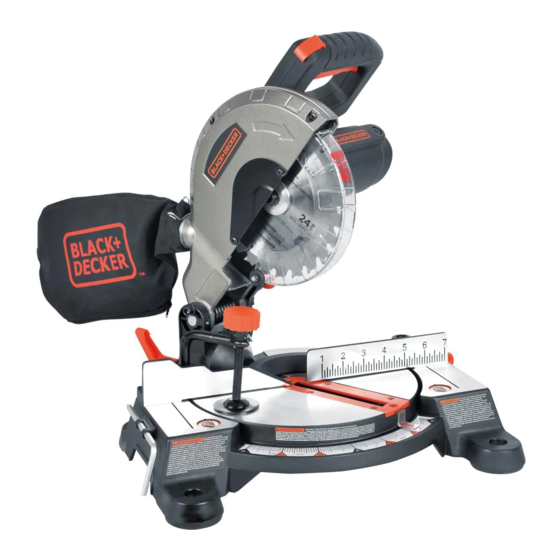
FUNCTIONAL DESCRIPTION 1. Upper blade guard 2. Safety lock-off button 3. Switch handle 4. Motor 5. Lower blade guard 6. Fence 7. Miter scale 8. Table insert 9. Mounting hole 10. Base 11. Blade wrench storage 12. Hold-down clamp 13. Dust bag 14. -
Page 12: Tools Needed To Remove Or Install Blade
TOOLS NEEDED TO REMOVE ASSEMBLY AND OR INSTALL BLADE ADJUSTMENTS WARNING Supplied • To avoid injury, do not connect this miter saw to the power source until it is completely assembled and adjusted, and you have read and understood this Instruction Manual. lade Wrench with •... -
Page 13: Installing The Hold-Down Clamp
Unlocking NOTE: To empty the dust bag, squeeze • Push down slightly on the switch the metal collar and remove from handle (1). exhaust port. Open zipper on underside • Pull out the hold-down latch (2). of bag and empty into waste container. •... -
Page 14: Removing And Installing The Blade
• NEVER cut metals or masonry products with this tool. This miter saw is designed for use on wood and wood-like products only. • Never depress the arbor lock button while the blade is under power or coasting. • Unplug the saw from the outlet. •... - Page 15 • Rotate the cover plate (2) back to its original position until the slot in the cover plate engages with the cover plate screw (1). Tighten the screw with a Phillips screwdriver. • Verify the operation of the guard. Make sure it does not bind or stick.
- Page 16 • Place the saw on a firm, level work • For portable use, place the saw on surface where there is room for a 3/4 in. thick piece of plywood. Bolt handling and properly supporting the base of the miter saw securely to the workpiece.
- Page 17 • Tilt the cutting arm to back to the right • Tilt the cutting arm to the left to 45° at 90°(0°) bevel and recheck bevel and recheck for alignment. for alignment. • Repeat above steps until the blade is at •...
-
Page 18: Adjusting Fence Squareness
MITER ANGLE POINTER ADJUSTMENT • Turn the adjustment bolt (2) out (FIGURE P) (counterclockwise) to decrease the • Move the table to the 0° positive stop. cutting depth or in (clockwise) to • Loosen the screw (4) that holds the increase the cutting depth. -
Page 19: Before Using The Miter Saw
OPERATING INSTRUCTIONS • Function of arm return spring and lower guard: Push the cutting arm BEFORE USING THE MITER SAW all the way down, then let it rise until WARNING it stops. The lower guard should • To reduce the risk of injury, turn fully close. -
Page 20: Plan Your Work
• Wear non-slip footwear. KEEP YOUR WORK AREA CLEAN • Tie back long hair. Cluttered areas and benches invite • Roll long sleeves above the elbow. accidents. • Noise levels vary widely. To avoid WARNING To avoid burns or other possible hearing damage, wear ear fire damage, never use the miter saw plugs when using any miter saw. - Page 21 USE EXTRA CAUTION WITH LARGE CAUTION Always use a work clamp OR ODD SHAPED WORKPIECES to maintain control and reduce the risk • Use extra supports (tables, sawhorses, of workpiece damage and personal blocks, etc.) for workpieces large injury. enough to tip. •...
- Page 22 • Release trigger switch and wait for all moving parts to stop before moving your hands and raising the cutting arm. • Unplug the miter saw. Before freeing jammed material: • Release trigger switch. • Wait for all moving parts to stop. •...
-
Page 23: Before Leaving The Saw
BEVEL CUT (FIGURE Z) • When a bevel cut is required, loosen the bevel lock handle (1). • Tilt the cutting head to the desired angle, as shown on the bevel scale (2). • The blade can be positioned at any angle, from a 90°... - Page 24 CUTTING BOWED MATERIAL CUTTING BASE MOLDING (FIGURE BB) (FIGURE DD) Base moldings and many other moldings WARNING To avoid injury from can be cut on a compound miter saw. materials being thrown, always unplug The setup of the saw depends on molding the saw to avoid accidental starting characteristics and application, as shown.
- Page 25 Most crown molding has a top rear angle (the section that fits flat against the ceiling) of 52°and a bottom rear angle (the section that fits flat against the wall) of 38°. In order to accurately cut crown molding for a 90° inside or outside corner, lay the molding with its broad back surface flat on the saw table.
- Page 26 Bevel/Miter Settings NOTE: The chart below references a compound cut for crown molding ONLY WHEN THE ANGLE BETWEEN THE WALLS EQUALS 90°. BEVEL MITER TYPE OF CUT SETTING SETTING Inside corner-Left side 33.9° 31.6° Right 1. Position top of molding against fence. 2.
-
Page 27: Crown Molding Chart
CROWN MOLDING CHART Compound Miter Saw Miter and Bevel Angle Settings Wall to Crown Molding Angle 52/38° Crown Molding 45/45° Crown Molding 52/38° Crown Molding 45/45° Crown Molding Angle Angle Miter Bevel Miter Bevel Miter Bevel Miter Bevel Between Between Setting Setting Setting... -
Page 28: Maintenance
MAINTENANCE Replace for the other side. To reassemble reverse the procedure. The ears on the WARNING metal end of the assembly go in the same • To reduce the risk of injury, turn unit hole the carbon part fits into. Tighten the off and disconnect it from power cap snugly, but do not overtighten. -
Page 29: Full Two-Year Home Use Warranty
FULL TWO-YEAR HOME USE To empty the dust bag, remove the WARRANTY sawdust bag from the dust collection port. Open the zipper on the sawdust Black+Decker warrants this product for bag and empty out the sawdust inside. two years against any defects in material Close the zipper and reinstall the dust or workmanship. -
Page 30: Troubleshooting
LATIN AMERICA: This warranty does not apply to products sold in Latin America. For products sold in Latin America, check country specific warranty information contained in the packaging, call the local company or see the website for warranty information. TROUBLESHOOTING SAW OPERATION Problem Possible Cause... - Page 31 MOTOR Problem Possible Cause Possible Solution • Motor does • Limit switch failure • Replace limit switch. not start. • Brush worn. • Replace brushes. See MAINTENANCE section. • Fuse blown or circuit breaker • Verify there is electrical power at tripped on home panel.
-
Page 32: Parts List
PARTS LIST 7-1/4 IN. MITER SAW MODEL NO. M1850BD TYPE 2 PARTS LIST FOR MITER SAW - (1) I.D. Description Size Q’ty I.D. Description Size Q’ty X6VM BAG-DUST ASS'Y X6WU COMPRESSION SPRING X6VN PC-GUARD ASS’Y X6WV C-RING ø8 X6VR VISE ASS'Y... - Page 33 7-1/4 IN. MITER SAW MODEL NO. M1850BD TYPE 2 PARTS LIST FOR MITER SAW - (2) I.D. Description Size Q’ty I.D. Description Size Q’ty X6XX LOCK NUT X6YQ HEX. SOC. HD. CAP BOLT X6XY CR. RE. COUNT HD. SCREW X6YR...
- Page 34 7-1/4 IN. MITER SAW MODEL NO. M1850BD TYPE 2 SCHEMATIC...