Table of Contents
Advertisement
Available languages
Available languages
INSTRUCTION MANUAL
BEFORE RETURNING THIS PRODUCT FOR A N Y REASON
PLEASE CALL 1 - 8 0 0 - 5 4 4 - 6 9 8 6
IF YOU SHOULD EXPERIENCE A PROBLEM WITH YOUR BLACK & DECKER PRODUCT,
C A L L 1 - 8 0 0 - 5 4 4 - 6 9 8 6
BEFORE YOU CALL, HAVE THE FOLLOWING INFORMATION AVAILABLE, CATALOG No.,
TYPE No., AND DATE CODE. IN MOST CASES, A BLACK & DECKER REPRESENTATIVE
CAN RESOLVE THE PROBLEM OVER THE PHONE. IF YOU HAVE A SUGGESTION OR COMMENT,
GIVE US A CALL.YOUR FEEDBACK IS VITA L TO BLACK & DECKER.
S AVE THIS MANUAL FOR FUTURE REFERENCE.
VEA EL ESPAÑOL EN LA CONTRAPORTADA.
POUR LE FRANÇAIS, VOIR LA COUVERTURE ARRIÈRE.
INSTRUCTIVO DE OPERACIÓN, CENTROS DE SERVICIO Y
P Ó L I Z A DE GARANTÍA. ADVERTENCIA: LÉASE ESTE
INSTRUCTIVO ANTES DE USAR EL P R O D U C TO.
Cat.No. FS210LS
Form No. 489624-00
DEC. '05
Copyright
2005 Black & Decker
Printed in China
©
Advertisement
Table of Contents

Related Manuals for Black & Decker FS210LS FireStorm


Summary of Contents for Black & Decker FS210LS FireStorm
-
Page 1: Instruction Manual
INSTRUCTION MANUAL BEFORE RETURNING THIS PRODUCT FOR A N Y REASON PLEASE CALL 1 - 8 0 0 - 5 4 4 - 6 9 8 6 IF YOU SHOULD EXPERIENCE A PROBLEM WITH YOUR BLACK & DECKER PRODUCT, C A L L 1 - 8 0 0 - 5 4 4 - 6 9 8 6 BEFORE YOU CALL, HAVE THE FOLLOWING INFORMATION AVAILABLE, CATALOG No., TYPE No., AND DATE CODE. -
Page 2: Safety Guidelines - Definitions
SAFETY GUIDELINES - DEFINITIONS This manual contains information that is important for you to know and understand. This information relates to protect- ing YOUR SAFETY and PREVENTING EQUIPMENT PROBLEMS. To help you recognize this information, we use the symbols to the right. Please read the manual and pay attention to these sections. Indicates an imminently hazardous situation which, if not avoided, will result in death or serious injury. - Page 3 GENERAL SAFETY RULES FAILURE TO FOLLOW THESE RULES MAY RESULT IN SERIOUS INJURY. 1. FOR YOUR OWN SAFETY, READ THE INSTRUCTION 13. USE RECOMMENDED ACCESSORIES. The use of MANUAL BEFORE OPERATING THE MACHINE. accessories and attachments not recommended by Learning the machine’s application, limitations, and Delta may cause damage to the machine or injury to the specific hazards will greatly minimize the possibility of user.
-
Page 4: Additional Safety Rules For Table Saws
ADDITIONAL SAFETY RULES FOR TABLE SAWS READ AND UNDERSTAND ALL WARNINGS AND OPERATING INSTRUCTIONS BEFORE USING THIS EQUIPMENT. Failure to follow all instructions listed below, may result in electric shock, fire, and/or serious personal injury or property damage. D O N O T O P E R ATE THIS MACHINE u n t i l it is 10. -
Page 5: Power Connections
POWER CONNECTIONS A separate electrical circuit should be used for your machine. This circuit should not be less than #12 wire and should be protected with a 20 Amp time lag fuse. If an extension cord is used, use only 3-wire extension cords which have 3- prong grounding type plugs and matching receptacle which will accept the machine’s plug. -
Page 6: Extension Cords
It is also necessary to replace the 120 volt plug, supplied with CURRENT the motor, with a UL/CSA Listed plug suitable for 240 volts CARRYING PRONGS and the rated current of the saw as illustrated in Fig. C. Contact your local Authorized Delta Service Center or qualified electrician for proper procedures to install the plug. -
Page 7: Table Saw Parts
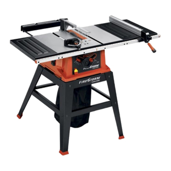
FUNCTIONAL DESCRIPTION F O R E W O R D Model FS210LS has big saw capacity at an economical price. It has an extra large, 17" x 34" aluminum table with extension and is powered by a heavy-duty 15 amp. motor with a floating jackshaft gear - the most powerful in its class. This saw is designed to give high quality performance with depth of cut capacity up to 3"... - Page 8 Fig. 3 RIP FENCE PARTS (11,12) 31-1/4”External Tooth Lockwasher for Splitter 11-Rip Fence Bracket(2) 12-Locking Handle for Rip Fence 32-Splitter Support Bracket BLADE RAISING HANDWHEEL PA RTS ( 1 3 , 1 4 , 1 5 , 1 6 , 1 7) 33-1/4-20X1/2”Hex Head Screws for Splitter Bracket(2) 13-Blade Raising and Lowering Handwheel 34-Wing Nut for Mounting Splitter Support Bracket...
- Page 9 Fig. 4 STAND PARTS 60-M8X1.25X45mm Hex Head Screw for Leg and 53-Leg(4) Base(2) 54-Top side Bracket(2) 61-M8X1.25X30mm Hex Head Screw for Leg and Base(2) 55-Top Front Bracket 62-5/16”Hex lock Nut(16) 56-Top Rear Bracket 63-5/16”Carriage Bolt(16) 57-Bottom side Brackets(2) 64-M8 Hex Nut(4) 58-Bottom Front Brackets(2) 65- M8 Flat washer(8) 59-Foot(4)
-
Page 10: Stand Assembly
STAND ASSEMBLY 1. The stand legs have protrusions which align with the holes in the top and bottom brackets. Assemble the stand as shown in Fig. 4A, using 16 carriage bolts and hex lock nuts. Do not completely tighten the hardware at this time. - Page 11 ASSEMBLING BLADE RAISING AND LOWERING HANDWHEEL 1. Insert special screw (C) through handle (B) Fig.5 and assembly handle to handwheel (A) by threading screw clockwise into handwheel. Then push on handle cover (D). Fig. 5 2. Fig. 6, illustrates the handle (B) assembled to handwheel (A).
-
Page 12: Blade Guard/Splitter Assembly
BLADE GUARD AND SPLITTER ASSEMBLY DISCONNECT MACHINE FROM POWER SOURCE. 1. IMPORTANT: THE BLADE GUARD AND SPLITTER ASSEMBLY MUST BE PROPERLY ALIGNED TO THE SAW BLADE IN ORDER TO PREVENT KICKBACK. 2. Position the blade 90 degrees to the table and lock in Fig. - Page 13 7. Assemble splitter (H) Fig. 14, to splitter support bracket (B) as shown using M6x1x20mm hex head screw (L), 1/4" external tooth washer, and 1/4" flat washer. Fig. 14 8. Fasten splitter (H) Fig. 15, to splitter support bracket using 1/4" flat washer, 1/4" external tooth lockwasher and M6 wing nut (M).
-
Page 14: Extension Wings
EXTENSION WINGS 1. Assemble left extension wing (Fig.18), to the saw table using 1/4-20X1”hex head screws (3), 1/4”flat washers (6), 1/4”lockwashers (3),1/4”hex nuts (3). 2. Assemble right extension wing into the threaded holes of the saw using 1/4”-20X5/8” hex head screws (3), 1/4”flat washers (3) 1/4”lockwashers (3). -
Page 15: Rip Fence
RIP FENCE 1. Thread handle (A) Fig. 21, into tapped hole (B) in fence cam (C). Fig. 21 2. Lower rip fence onto table as shown in Fig. 22, making certain rear clamp hooks over back edge of table. 3. The rip fence is usually operated on the right hand side of the saw table. - Page 16 MITER GAGE HOLDER DISCONNECT MACHINE FROM POWER SOURCE. 1. Assemble spring clip (E) Fig. 24, to the miter gage holder (A) as shown using a M4x.7x10mm pan head screw (F), 3/16" lockwasher and M4x.7 hex nut. NOTE: Hex nut (G) Fig. 25, will fit into the recess at the back of the miter gage holder (A) to keep spring clip (E) Fig.
- Page 17 OUTFEED SUPPORT 1. LOOSELY fasten both brackets (A) Fig. 29, to the bottom left side of the saw table as shown, using two M6x1x15mm phillips hex head screws (B) and M6.1 lockwashers (C). Assemble two remaining brackets to the bottom right side of saw table in the same manner. Fig.
-
Page 18: Starting And Stopping Saw
OPERATING CONTROLS AND ADJUSTMENTS STARTING AND STOPPING SAW The on/off switch (A) Fig. 34 is located on the front of the saw cabinet. To turn the saw “ON”, move the switch (A) up to the “ON” position. To turn the saw “OFF”, move the switch (A) down to the “OFF”... -
Page 19: Blade Tilting Control
BLADE TILTING CONTROL To tilt the saw blade, loosen blade tilting lock handle (A) Fig. 37, move handwheel (B) until the blade is at the desired angle and tighten lock handle (A). NOTE: The lock handle (A) is spring-loaded and can be repositioned by pulling out on the handle (A) and repositioning it on the serrated stud located underneath the handle. -
Page 20: Rip Fence Operation And Adjustments
RIP FENCE OPERATION AND ADJUSTMENTS 1. To move the rip fence (A) Fig. 40, along the table, lift up fence locking lever (B), slide the fence to the desired location on the table and push down fence locking lever (B) to lock the fence in position. 2. -
Page 21: Changing The Blade
ADJUSTING BLADE PARALLEL TO MITER GAGE SLOTS The blade was adjusted parallel to the miter gage slots at the factory. In order to insure accurate cuts and help prevent kickback when cutting, this adjustment should be rechecked and if necessary, readjusted as follows: 1. -
Page 22: Cross-Cutting
COMMON SAWING OPERAT I O N S Common sawing operations include ripping and crosscutting plus a few other standard operations of a fundamental n a t u re. As with all power machines, there is a certain amount of hazard involved with the operation and use of the machine. - Page 23 RIPPING Ripping is cutting lengthwise through a board. The rip fence (A) Fig. 46 is used to position and guide the work. One edge of the work rides against the rip fence while the flat side of the board rests on the table. Since the work is pushed along the fence, it must have a straight edge and make solid contact with the table.
- Page 24 USING AUXILIARY WOODFACING ON RIP FENCE Wood facings (A) Fig. 50 are necessary on some special operations to one or both sides of the rip fence. The wood facing is attached to the fence with screws through the holes in the fence. Most work will require a 3/4 " stock, although an occasional job may require 1"...
- Page 25 2. Attach the dado head set (D) Fig. 55, to the saw arbor. NOTE: THE OUTSIDE ARBOR FLANGE CAN NOT BE USED WITH THE DADO HEAD SET, T I G H T E N T H E ARBOR NUT AGAINST THE DADO HEAD SET BODY. DO NOT LOSE THE OUTSIDE ARBOR FLANGE.
- Page 26 CONSTRUCTING A FEATHERBOARD Fig. 57, illustrates dimensions for making a typical featherboard. The material which the featherboard is constructed of, should be a straight piece of wood that is free of knots and cracks. Featherboards are used to keep the work in contact with the fence and table and help prevent kickbacks.
-
Page 27: Troubleshooting Guide
TROUBLESHOOTING GUIDE BE SURE TO FOLLOW SAFETY RULES AND INSTRUCTIONS TROUBLE! SAW WILL NOT START WHAT’S WRONG? WHAT TO DO… 1.Saw not plugged in. 1.Plug in saw. 2.Fuse blown or circuit breaker tripped. 2.Replace fuse or reset circuit breaker. 3.Cord damaged. 3.Have cord replaced by authorized service center. -
Page 28: Constructing A Push Stick
CONSTRUCTING A PUSH STICK When ripping work less than 4 inches wide, a push stick should be used to complete the feed and could easily be made from scrap material by following the pattern shown in Fig. 59. Fig. 59... -
Page 29: Service Information
ACCESSORIES Recommended accessories for use with your tool are available from your local dealer or authorized service center. If you need assistance regarding accessories, please call:1 - 8 0 0 - 5 4 4 - 6 9 8 6 . The use of any accessory not recommended for use with this tool could be hazardous.. - Page 30 MODE D'EMPLOI AVANT DE RETOURNER LE PRODUIT, PEU IMPORTE LA RAISON PRIÈRE DE COMPOSER 1 800 544-6986 CONSERVER CE MODE D’EMPLOI POUR UN USAGE ULTÉRIEUR.
-
Page 31: Règles Générales De Sécurité
LIGNES DIRECTRICES EN MATIÈRE DE SÉCURITÉ — DÉFINITIONS Ce mode d’emploi contient de l’information qu’il est important de connaître et de comprendre. Cette information concerne VOTRE SÉCURITÉ et vise à ÉVITER TOUT PROBLÈME D’ÉQUIPEMENT. Pour vous aider à reconnaître ces informations, nous utilisons les symboles à... - Page 32 RÈGLES GÉNÉRALES DE SÉCURITÉ NÉGLIGER DE SUIVRE CES RÈGLES RISQUE D’ENTRAÎNER DES BLESSURES GRAVES. POUR SA PROPRE SÉCURITÉ, LIRE LE MODE 12. UTILISATION DE L’OUTIL APPROPRIÉ. Ne pas forcer un D’EMPLOI AVANT D’UTILISER L’OUTIL. L’apprentissage appareil ou un accessoire pour accomplir un travail pour de l’utilisation de cet outil, des restrictions, et des risques lequel il n'est pas conçu.
- Page 33 RÈGLES DE SÉCURITÉ SUPPLÉMENTAIRES POUR LES SCIES DE TABLE LIRE ATTENTIVEMENT TOUTES LES MISES EN GARDE ET DIRECTIVES D’UTILISATION AVANT D’UTILISER CET ÉQUIPEMENT. À défaut de suivre les directives sous-mentionnées, un choc électrique, un incendie, des dommages ou une blessure corporelle grave pourraient survenir. 1.
-
Page 34: Directives De Mise À La Terre
CONNEXIONS ÉLECTRIQUES Un circuit électrique séparé doit être utilisé pour l’appareil. Ce circuit doit utiliser un câble de calibre 12 au minimum et doit être protégé par un fusible temporisé de 20 A. Si vous utilisez une rallonge, n’utiliser que des rallonges à 3 fils pourvues d’une fiche de mise à... - Page 35 Il est également obligatoire de remplacer la fiche de 120 LAMES volts, fournie avec le moteur, par une fiche convenable pour CONDUCTRICES du 240 volts, homologuée UL/CSA, prévue pour le courant nominal de la scie comme indiqué à la fig. C. Communiquer avec le Centre de réparation autorisé...
-
Page 36: Description Fonctionnelle
DESCRIPTION FONCTIONNELLE AVA N T- P R O P O S Le modèle FS210LS de Delta dispose d’une scie haute capacité à un prix abordable. Il également comporte une table e x t r a - l a rge en aluminium de 52 x 104 cm (17 x 34 po) avec rallonges et est doté d’un moteur de 15 ampères de type industriel avec arbre de renvoi flottant : le plus puissant de sa catégorie. - Page 37 Fig. 3 PIÈCE DU GUIDE LONGITUDINAL (11,12) 31– (2) rondelles à denture extérieure de 6,4 mm (1/4 po) pour le support du couteau séparateur 11– Guide longitudinal 32– Support du couteau séparateur 12– Poignée de verrouillage du guide longitudinal PIÈCES DU VOLANT DE RELÈVEMENT DE LA LAME 33–...
- Page 38 Fig. 4 PIÈCES DU SOCLE 60– (2) vis à tête hexagonale M8X1,25X45 mm 53– (4) pattes pour patte et base 54– (2) traverses supérieures latérales 61– (2) vis à tête hexagonale M8X1,25X30 mm pour patte et base 55– Traverse supérieure avant 62–...
-
Page 39: Assemblage Du Socle
ASSEMBLAGE DU SOCLE 1. Les pattes du socle comportent des saillies qui s’aligneront avec les trous dans les traverses supérieures et inférieures. Assembler le socle comme l’illustre la fig. 4A, à l’aide de 16 boulons de carrosserie et écrous hexagonaux à embase. Ne pas serrer complètement la boulonnerie pour le moment. - Page 40 ASSEMBLAGE DE LA LAME VOLANT d’abaissement et de RELÈVEMENT 1. Insérer la vis spéciale (C) dans la poignée (B) fig. 5 puis visser la vis en sens horaire pour assembler la poignée sur le volant (A). Puis enfoncer le capuchon de la poignée (D).
- Page 41 ENSEMBLE DE PROTÈGE-LAME ET COUTEAU SÉPARATEUR DÉBRANCHER L’APPAREIL DE LA SOURCE D’ALIMENTATION. 1. IMPORTANT : POUR EMPCHER TOUT REBOND OU RECUL, L’ENSEMBLE DU PROTÈGE-LAME ET COUTEAU SÉPA R ATEUR DOIT ÊTRE CORRECTEMENT ALIGNÉ AVEC LA LAME DE LA SCIE. 2. Positionner la lame à angle droit (90°) par rapport à la Fig.
- Page 42 7. Assembler le couteau séparateur (H) fig. 14, au support (B) comme indiqué à l’aide d’une vis à tête hexagonale M6x1x20 mm (L), d’une rondelle à denture extérieure de 6,4 mm (1/4 po) et une rondelle plate de 6,4 mm (1/4 po). Fig.
- Page 43 RALLONGES 1. Assembler la rallonge gauche (fig. 18) à la table de la scie avec trois vis à tête hexagonale 6,4 mm - 20 x 25,4 mm (1/4 po - 20 x 1 po), six rondelles plates de 6,4 mm (1/4 po), trois contre-écrous et trois écrous hexagonaux. 2.
-
Page 44: Guide D'onglet
GUIDE LONGITUDINAL 1. Visser la poignée (A) fig. 21, dans le trou taraudé (B) de la came du guide (C). Fig. 21 2. Abaisser le guide longitudinal sur la table comme indiqué à la fig. 22, en s’assurant que l’arrière se fixe bien au-dessus du bord arrière de la table. - Page 45 PORTE-GUIDE D’ONGLET DÉBRANCHER L’APPAREIL DE LA SOURCE D’ALIMENTATION. 1. Assembler l’attache à ressort (E) fig. 24, au porte- guide d’onglet (A) comme indiqué avec une vis cylindrique à dépouille (F) M4x0,7x10 mm, un contre- écrou 4,8 mm (3/16 po) et un écrou hexagonal M4x0,7. NOTE : l’écrou hexagonale (G) fig.
- Page 46 APPUI ARRIÈRE 1. Fixer LÉGÈREMENT les deux supports (A) fig. 29, au côté gauche inférieur de la table de la scie comme indiqué, avec deux vis à tête hexagonale cruciformes M6x1x15 mm (B) et des contre - é c rous M6,1 (C). Assembler les deux autres traverses du côté...
- Page 47 UTILISATION DES COMMANDES ET RÉGLAGES DÉMARRAGE ET ARRÊT DE LA SCIE L’interrupteur marche/arrêt (A) fig. 34 est logé à l’avant de l’armoire de la scie. Pour mettre la scie sous tension, déplacer l’interrupteur (A) vers le haut en position de marche.
- Page 48 COMMANDE D’INCLINAISON DE LA LAME Pour incliner la lame de la scie, desserrer la poignée de blocage (A) Fig. 37, tourner le volant (B) jusqu’à ce que la lame soit à l’angle souhaité puis resserrer la poignée de blocage (A). REMARQUE : la poignée de blocage (A) est à...
- Page 49 UTILISATION ET RÉGLAGE DU GUIDE LONGITUDINAL 1. Pour déplacer le guide longitudinal (A) fig. 40, le long de la table, relever le levier de blocage du guide (B), glisser le guide sur la table à l’endroit souhaité, puis abaisser le levier de blocage du guide (B) pour le bloquer dans cette position.
-
Page 50: Changement De La Lame
RÉGLAGE DE LA LAME EN PARALLÈLE AUX RAINURES DU GUIDE D’ONGLET À l’usine, la lame a été réglée parallèlement aux rainures du guide d’onglet. Pour garantir une précision de coupe et éviter l’effet de rebond, revérifier ce réglage et réajuster au besoin comme suit : 1. - Page 51 O P É R ATIONS COURANTES DE SCIAGE Les opérations courantes de sciage comprennent le sciage en long et le tronçonnage, ainsi que quelques autre s opérations standard de nature fondamentale. Comme pour tout appareil électrique, le fonctionnement et l’utilisation de l ’...
- Page 52 SCIAGE EN LONG La coupe d’une planche dans sa longueur est connue sous le nom de sciage en long. Utiliser le guide longitudinal (A) fig. 46, pour positionner et guider la pièce. L’un des bords de la pièce vient s’appuyer contre le guide longitudinal tandis que le côté...
- Page 53 UTILISATION DU PAREMENT EN BOIS AUXILIAIRE AVEC LE GUIDE LONGITUDINAL Pour certaines opérations spéciales, il est nécessaire de placer des planches de repères (A) fig. 50 sur un côté du guide, ou sur les deux. Fixer la planche de repère sur le guide en mettant des vis dans les trous du guide.
- Page 54 2. Fixer l’ensemble à rainurer (D) fig. 55, sur l’arbre de la scie. REMARQUE : LA BRIDE D’AXE EXTERNE NE PEUT ÊTRE UTILISÉE AVEC L’ENSEMBLE À RAINURER, RESSERRER L’ÉCROU D’ARBRE CONTRE LE CORPS DE L’ENSEMBLE À RAINURER. NE PAS PERDRE LA BRIDE D’AXE EXTERNE. ELLE SERA NÉCESSAIRE POUR FIXER À...
- Page 55 CONSTRUCTION D’UNE PLANCHE EN ÉVENTAIL La fig. 57 illustre les dimensions utilisées pour la fabrication d’une planche en éventail typique. Utiliser une pièce de bois droite exempte de n?uds et de fissures pour la fabrication de la planche en éventail. Les planches en éventail sont utilisées pour maintenir la pièce en contact avec le guide et la table et d’éviter les effets de rebond.
-
Page 56: Guide De Dépannage
GUIDE DE DÉPANNAGE SUIVRE LES RÈGLES ET CONSIGNES DE SÉCURITÉ PROBLÈME ! LA SCIE NE DÉMARRE PAS QUEL EST LE PROBLÈME ? QUE FAIRE… 1.Scie non branchée. 1.Brancher la scie. 2.Fusible grillé ou disjoncteur déclenché.2.Remplacer le fusible ou réinitialiser le disjoncteur. 3.Cordon endommagé. - Page 57 FA B R I C ATION D'UN POUSSOIR » « Pour scier en long un ouvrage de moins de 10,2 cm (4 po) de large, utiliser un poussoir pour terminer la coupe. Il est facile de fabriquer un poussoir avec des déchets de découpe en suivant le modèle indiqué à la fig. 59.
- Page 58 ACCESSOIRES Les accessoires recommandés pouvant être utilisés avec l’outil sont disponibles auprès de votre distributeur local ou centre de réparation autorisé. Pour tout renseignement concernant les accessoires, composer le : 1-800-544-6986 l’utilisation de tout accessoire non recommandé avec l’outil pourrait s’avérer dangereuse. E n t r e t i e n N’utiliser qu’un détergent doux et un chiffon humide pour nettoyer l’outil.
- Page 59 MANUAL DE INSTRUCCIONES ANTES DE DEVOLVER ESTE PRODUCTO POR CUALQUIER RAZÓN, POR FAVOR LLAME AL (55)5326-7100 CONSERVE ESTE MANUAL PARA FUTURAS CONSULTAS...
-
Page 60: Instrucciones Importantes Sobre Seguridad
DEFINICIONES DE LAS NORMAS DE SEGURIDAD Es importante que usted conozca y comprenda la información incluida en este manual. Esta información se relaciona con la protección de SU SEGURIDAD y la PREVENCIÓN DE PROBLEMAS CON EL EQUIPO. Para ayudarlo a reconocer esta información, utilizamos los símbolos que se incluyen a la derecha. - Page 61 NORMAS GENERALES DE SEGURIDAD LA FALTA DE CUMPLIMIENTO DE ESTAS NORMAS PUEDE PROVOCAR LESIONES GRAVES. INSTRUCCIONES IMPORTANTES SOBRE SEGURIDAD PARA SU PROPIA SEGURIDAD, LEA EL MANUAL DE UTILICE EL CORDÓN DE EXTENSIÓN ADECUADO. INSTRUCCIONES ANTES DE UTILIZAR LA MÁQUINA. Al Asegúrese de que el cordón de extensión esté...
- Page 62 NORMAS DE SEGURIDAD ADICIONALES PARA LAS SIERRAS DE MESA LEA Y COMPRENDA TODAS LAS ADVERTENCIAS Y LAS INSTRUCCIONES DE OPERACIÓN ANTES DE UTILIZAR ESTE EQUIPO. EL INCUMPLIMIENTO DE CUALQUIERA DE LAS INSTRUCCIONES ENUMERADAS A CONTINUACIÓN PUEDE PROVOCAR DESCARGA ELÉCTRICA, INCENDIO O LESIONES PERSONALES GRAVES O DAÑOS A LA PROPIEDAD.
-
Page 63: Conexiones Eléctricas
CONEXIONES ELÉCTRICAS Debe utilizar un circuito eléctrico independiente para su máquina. Este circuito no debe ser menor a un cable Nº 12 y debe estar protegido con un fusible de acción retardada de 20 amperios. Si utiliza un cable prolongador, debe ser únicamente de 3 conductores, que tenga enchufe a tierra de 3 patas y tomacorrientes correspondientes que acepten el enchufe de la máquina. -
Page 64: Cables Prolongadores
También debe volver a colocar el enchufe de 120 voltios, PATAS DE provisto con el motor, con un enchufe UL/CSA adecuado CONDUCCIÓN para 240 voltios y para la corriente nominal de la sierra, DE CORRIENTE según se muestra en la Fig. C. Comuníquese con su Centro de mantenimiento Delta autorizado local o a un electricista calificado para conocer los procedimientos adecuados para instalar el enchufe. -
Page 65: Descripción De Las Funciones
DESCRIPCIÓN DE LAS FUNCIONES I N T R O D U C C I Ó N El modelo FS210LS posee una gran capacidad de sierra a un precio económico. Posee una mesa de aluminio extra grande de 431,8 mm x 863,6 mm (17" x 34") con extensión y alimentada por un motor para trabajo pesado de 15 amp. con engranaje de contraeje flotante, el más potente de su clase. - Page 66 Fig. 3 PARTES DE LA GUÍA DE CORTE LONGITUDINAL 31- Arandela de bloqueo de diente externo de 6,35 mm (11,12) (1/4”) para la abrazadera del hendedor (2) 32- Abrazadera para el soporte del hendedor 11- Guía de corte longitudinal 33- Tornillos de cabeza hexagonal de 1/4-20 X 1/2” 12- Mango de bloqueo para la guía de corte longitudinal PA RTES DEL VOLANTE PARA ELEVAR LA HOJA para la abrazadera del hendedor (2)
- Page 67 Fig. 4 60- Tornillo de cabeza hexagonal M8 X 1,25 X 45 mm PARTES DE LA BASE para la pata y la base (2) 53- Pata (4) 61- Tornillo de cabeza hexagonal M8 X 1,25 X 30 mm para la pata y la base (2) 54- Abrazadera lateral superior (2) 62- Tuerca de bloqueo hexagonal de 7,93 mm (5/16") 55- Abrazadera frontal superior...
-
Page 68: Ensamblaje De La Base
ENSAMBLAJE DE LA BASE 1. Las patas de la base poseen protuberancias que deben alinearse con los orificios en las abrazaderas superiores e inferiores. Ensamble la base como se muestra en la Fig. 4A, con 16 pernos de soporte y tuercas de bloqueo hexagonales. - Page 69 ENSAMBLADO DE LA HOJA VOLANTE PARA ELEVAR Y BAJAR 1. Inserte el tornillo especial (C) a través del mango (B), Fig. 5, y ensamble el mango al volante (A) enroscando el tornillo en el sentido de las agujas del reloj en el volante. A continuación, presione la cubierta del mango (D).
- Page 70 ENSAMBLE DE LA GUARDA DE LA HOJA Y DEL HENDEDOR DESCONECTE LA MÁQUINA DE LA FUENTE DE ENERGÍA. 1. IMPORTANTE: EL ENSAMBLE DE LA GUARDA DE LA HOJA Y DEL hendedor DEBE ESTAR CORRECTAMENTE ALINEADO A LA HOJA DE LA SIERRA PARA PREVENIR EL RETROCESO.
- Page 71 7. Ensamble el hendedor (H), Fig. 14, a la abrazadera para el soporte del hendedor (B), como se muestra con un tornillo de cabeza hexagonal M6 x 1 x 20 mm (L), la arandela de diente externo de 6,35 mm (1/4") y la arandela plana de 6,35 mm (1/4").
- Page 72 BASES DE EXTENSIÓN 1. Ensamble la base de extensión, (Fig.18), a la mesa de la sierra con los tornillos de cabeza hexagonal 1/4-20 X 1”(3), las arandelas planas de 6,35 mm (1/4”) (6), las arandelas de bloqueo de 6,35 mm (1/4”) (3), las tuercas hexagonales de 1/4” (3). 2.
- Page 73 GUÍA DE CORTE LONGITUDINAL 1. Enrosque el mango (A), Fig. 21, en el orificio roscado (B) en la leva de la guía (C). Fig. 21 2. Baje la guía de corte longitudinal a la mesa como se muestra en la Fig. 22, y asegúrese de que la abrazadera trasera se enganche en el extremo posterior de la mesa.
- Page 74 SUJETADOR DEL CALIBRADOR DE INGLETE DESCONECTE LA MÁQUINA DE LA FUENTE DE ENERGÍA. 1. Ensamble la pinza de resorte (E), Fig. 24, al sujetador del calibrador de inglete (A) como se muestra, utilizando un tornillo de cabeza troncocónica M4 x 0,7 x 10 mm (F), una arandela de bloqueo de 4,763 mm (3/16") y una tuerca hexagonal M4 x 0,7.
- Page 75 SOPORTE DE AVANCE DE SALIDA 1. Ajuste sin demasiada firmeza ambas abrazaderas (A), Fig. 29, al lado inferior izquierdo de la mesa de la sierra como se muestra con dos tornillos de cabeza hexagonal phillips M6 x 1 x 15 mm (B) y arandelas de bloqueo M6 0,1 (C).
- Page 76 CONTROLES DE OPERACIÓN Y AJUSTES ENCENDIDO Y APAGADO DE LA SIERRA El interruptor de encendido/apagado (A), Fig. 34, está ubicado en la parte delantera del gabinete de la sierra. Para “ENCENDER” la sierra, mueva el interruptor (A) hacia arriba hasta la posición de “ENCENDIDO” (ON). Para “APAGAR”...
-
Page 77: Control De Inclinación De La Hoja
CONTROL DE INCLINACIÓN DE LA HOJA Para inclinar la hoja de la sierra, afloje el mango de bloqueo de inclinación (A), Fig. 37, mueva el volante (B) hasta que la hoja esté en el ángulo deseado y ajuste el mango de bloqueo (A). NOTA: el mango de bloqueo (A) funciona a resorte y se puede volver a colocar sacándolo del mango (A) y colocándolo en la clavija dentada debajo del mango. - Page 78 OPERACIÓN DE LA GUÍA DE CORTE LONGITUDINAL Y AJUSTES 1. To move the rip fence (A) Fig. 40, along the table, lift 1. Para mover la guía de corte longitudinal (A), Fig. 40, a lo largo de la mesa, levante la palanca de bloqueo de la guía (B), deslice la guía a la ubicación deseada en la mesa y presione la palanca de bloqueo de la guía (B) para trabar la guía en su lugar.
-
Page 79: Cambio De La Hoja
AJUSTE DE LA HOJA EN PARALELO A LAS RANURAS DEL CALIBRADOR DE INGLETE La hoja viene instalada de fábrica en forma paralela a las ranuras del calibrador de inglete. Para garantizar cortes precisos y prevenir el retroceso durante el corte, este ajuste debe verificarse nuevamente y, de ser necesario, reajustarse de la siguiente manera: 1. -
Page 80: Corte Transversal
OPERACIONES MÁS COMUNES DE CORTE CON SIERRA Las operaciones comunes de corte con sierra incluyen los cortes longitudinales y transversales, además de algunas otras operaciones estándar fundamentales. Como sucede con todas las máquinas eléctricas, hay un determinado m a rgen de peligro relacionado con el funcionamiento y el uso de la máquina. El uso de la máquina de conformidad con las medidas de seguridad, y con la precaución que éstas exigen, disminuirá... -
Page 81: Corte Longitudinal
CORTE LONGITUDINAL El corte longitudinal se realiza a lo largo de una tabla. La guía de corte longitudinal (A), Fig. 46, se utiliza para posicionar y guiar el trabajo. Un borde del trabajo corre contra la guía de corte longitudinal mientras que el lado plano de la tabla descansa sobre la mesa. - Page 82 UTILIZACIÓN DE UN REVESTIMIENTO DE MADERA EN LA GUÍA DE CORTE LONGITUDINAL Los revestimientos de madera (A) Fig. 50, son necesarios en algunas operaciones especiales en uno o ambos lados de la guía de corte longitudinal. El revestimiento de madera se sujeta a la guía con tornillos a través de los orificios de la guía.
- Page 83 2. Sujete el juego de cabezales para ranuras (D) Fig. 55, al eje de la sierra. N O TA: LA BRIDA EXTERNA DEL EJE NO PUEDE UTILIZARSE CON EL JUEGO DE CABEZALES PA R A RANURAS; AJUSTE LA TUERCA DEL EJE CONTRA EL CUERPO DEL JUEGO DE CABEZALES PA R A RANURAS.
- Page 84 CONSTRUCCIÓN DE UNA TABLA DE CANTO BISELADO La Fig. 57 ilustra las dimensiones para realizar una tabla de canto biselado típica. El material de la tabla de canto biselado debe ser una pieza de madera recta que no tenga nudos ni grietas. Las tablas de canto biselado se utilizan para mantener el trabajo en contacto con la guía y la mesa y para prevenir retrocesos.
-
Page 85: Guía De Detección De Problemas
GUÍA DE DETECCIÓN DE PROBLEMAS ASEGÚRESE DE SEGUIR LAS REGLAS E INSTRUCCIONES DE SEGURIDAD PROBLEMA: LA SIERRA NO ENCIENDE ¿QUÉ SUCEDE? QUÉ HACER… 1. La sierra no está enchufada. 1. Enchufe la sierra. 2. Fusible quemado o interruptor 2. Reemplace el fusible o reinicie el automático activado. - Page 86 CONSTRUCCIÓN DE UNA VARA PARA EMPUJAR Cuando realice un corte longitudinal en una pieza con un ancho menor a 10 cm (4 pulgadas), puede utilizar una vara para empujar a fin de completar la introducción en la hoja. Esta vara se puede hacer fácilmente con material de desecho, siguiendo la ilustración de la Fig.
- Page 87 ACCESORIOS Los accesorios que se recomiendan para la herramienta están disponibles en su distribuidor local o en el centro de mantenimiento autorizado. Si necesita ayuda con respecto a los accesorios, llame al: (55)5326-7100. el uso de accesorios no recomendados para utilizar con esta herramienta puede resultar peligroso. M a n t e n i m i e n t o Para limpiar la herramienta, sólo utilice jabón suave y un paño húmedo.