Table of Contents
Advertisement
Quick Links
Advertisement
Table of Contents

Related Manuals for Bosch C 80


Summary of Contents for Bosch C 80
- Page 1 Data Logger and Sensor Interface C 80 Manual Version 1.0 04/08/2021...
-
Page 2: Table Of Contents
12.2 Configuring inputs ....................................... 12.3 Configuring computed sources ..................................12.4 Hysteresis..........................................13 Online Measurement and Calibration .......................... 13.1 Setting up an online measurement................................13.2 Online calibration of measurement channels............................13.3 Online calibration of multipoint adjustment channels .......................... ii / 144 Manual_C_80 Bosch Motorsport... - Page 3 20.4 Measurement labels ......................................20.5 GPS troubleshooting......................................21 Fuel Consumption Calculation ............................21.1 Setting up fuel consumption calculation and tank management ..................... 21.2 Fuel consumption diagnosis/counter reset..............................22 RaceCon Shortcuts................................23 REACH Statement ................................24 Disposal.................................... Bosch Motorsport Manual_C_80 iii / 144...
-
Page 4: Preparation
1 | Preparation 1 Preparation Use the C 80 only as intended in this manual. Any maintenance or repair must be per- formed by authorized and qualified personnel approved by Bosch Motorsport. Operation of the C 80 is only certified with the combinations and accessories that are spe- cified in this manual. -
Page 5: Warnings And Safety Instructions
Warning of death or serious injury, which can occur if this is not observed. Caution CAUTION Nature and source of danger Consequences Warning of slight bodily injury in case of Disregard. Notice NOTICE Nature and source of danger Consequences Warning of damage to equipment in case of ignoring. Bosch Motorsport Manual_C_80 5 / 144... -
Page 6: Onboard Network Concept
Be careful to observe current limits of wires and connector pins! IGN- Switch UBAT Star connection switched pos. terminal (term30) positive terminal Electric Loads Main KL15 Switch KL30 Bosch Motorsport Device diagnosis connector µC LS_SWITCH1…4 KL31 UBATT_FUSE GND_Starpoint SENSPWR10 Star connection Chassis dig. sensors (e.g. wheelspeed) -
Page 7: Technical Data
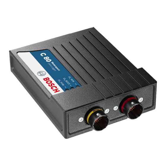
Technical Data | 4 4 Technical Data We offer the C 80 in two basic versions, on the one hand as a data logger and on the other hand as a sensor interface. Choose between these basic variants and combine or add functionalities now or later. - Page 8 Wire Ethernet_0 - RX+ Ethernet Channel2 Rx minus Wire Ethernet_0 - RX- CAN_A_H CAN_A - HIGH CAN_A_L CAN_A - LOW CAN_B_H CAN_B - HIGH CAN_B_L CAN_B - LOW USB Power 500mA USB_Power USB Data Plus USB_OTG_Plus 8 / 144 Manual_C_80 Bosch Motorsport...
- Page 9 REV3_M DHE I/P or Inductive - KW- REV4_P DHE I/P or Inductive - KW+ REV4_M DHE I/P or Inductive - KW- ANAIN_M1_7 0 to 5V Analog ANAIN_M1_8 0 to 5V Analog ANAIN_M1_9 0 to 5V Analog Bosch Motorsport Manual_C_80 9 / 144...
- Page 10 ANAIN_M2_4 0 to 5V Analog ANAIN_M2_5 0 to 5V Analog ANAIN_M2_6 0 to 5V Analog ANAIN_M2_7 0 to 5V Analog ANAIN_M2_8 0 to 5V Analog ANAIN_M2_9 0 to 5V Analog ANAIN_M2_10 0 to 5V Analog LAPTRIGGER 10 / 144 Manual_C_80 Bosch Motorsport...
-
Page 11: Mechanical Drawing
Mechanical Drawing | 5 5 Mechanical Drawing Bosch Motorsport Manual_C_80 11 / 144... -
Page 12: Communication Channels
6 Communication Channels CAN bus The C 80 has two CAN buses configurable as input and output. Different baud rates are selectable. Please note that the C 80 does not contain any CAN termination resistors. Thus the CAN termination resistors need to be integrated into the wiring loom. -
Page 13: System Configuration Tool Racecon
System Configuration Tool RaceCon | 7 7 System Configuration Tool RaceCon RaceCon is an all integrated software tool for configuration and calibration of Bosch Motorsport hardware products, such as ECUs, displays, loggers. The communication is based on Bosch Motorsport MSA-Box interface. -
Page 14: First Steps
8 | First Steps 8 First Steps Install the software required for the operation of the C 80. It is developed for Windows system software. The following software versions are used in this manual: – C 80 setup, configuration and calibration: RaceCon Version 2.10. -
Page 15: Setting Up A New Racecon Project
The following screenshot shows an overview of the RaceCon Main Screen with its areas. All (sub-) windows are resizable and dockable. You can find them under the ‘Windows’ tab. Main Area Project Toolbox Tree Message Area Data Area Bosch Motorsport Manual_C_80 15 / 144... - Page 16 Start the RaceCon software. In the ‘File’ menu select ‘New project’ to create a new project. In the Toolbox select the C 80 and drag it into the Main Area. A pop up window to specify the C 80 program archive appears.
- Page 17 An information shows if the archive is valid or not. Click ‘Next’. Select ‘Race track’ or ‘Testbench’ mode according to your application. Click ‘Finish’. The C 80 is inserted into the project and RaceCon tries to connect to the device. Bosch Motorsport Manual_C_80 17 / 144...
- Page 18 8 | First Steps RaceCon detects configuration differences between the C 80 and the RaceCon project and asks for permission for data download. Click ‘Yes’ to download the configurations to the device or ‘No’ to continue without downloading the data.
-
Page 19: Feature Activation
– The feature activation status is stored permanently in the device and requires activat- ing once only. – As the activation key is device specific, a key delivered with one C 80 does not work on any other C 80. - Page 20 8 | First Steps Ensure a connection to the device. To activate a feature, double-click on ‘C 80’ in the Project Tree. Click on the ‘Features info’ tab in the Main Area. 1st: Double-click on DDU 2nd: Click on 'Features info' The ‘C 80 features info’...
-
Page 21: First Recording (Quick Start)
First Steps | 8 Perform these steps to activate other features you purchased. Switch the car’s ignition off and on again to cycle the power of C 80. 8.4 First recording (Quick Start) This chapter explains the configuration of the recording of the battery voltage channel. - Page 22 Drag + Drop Click on the ‘Download’ button in the upper left corner. The configuration download starts and the C 80 carries out a reset. Now you can find the ‘ub’ measurement channel in the ‘Data Area’. As we did not define global start conditions, recording starts immediately.
- Page 23 12. Click on the ‘Current Import’ tab. 13. Click on ‘Import’ in the lower right corner. If the ‘Import all on connect’ box is checked, the data transmission from the C 80 starts automatically. Measurement files are stored automatically in the folder defined under ‘Settings’.
-
Page 24: Set Date And Time
The ‘ub’ measurement channel‘s graph is displayed. 8.5 Set date and time The C 80 is equipped with a real time clock which is supplied by an internal accumulator. Once this accumulator is charged correctly by 12 V supply of the display, ‘Date & Time’... - Page 25 First Steps | 8 Alternatively, click on ‘Set Date & Time’ in the context menu of the device. A ‘Set Date & Time’ menu opens Set the current local date and time as coordinated universal time. Bosch Motorsport Manual_C_80 25 / 144...
-
Page 26: Color Indication
– In the status area in the upper left corner. – As a background, as well as a little dot around the display icon in the ‘System win- dow’. – As a colored stripe beside the device name in the project tree. 26 / 144 Manual_C_80 Bosch Motorsport... -
Page 27: Assign The Mounting Location
At delivery the default role of the devices is set. There is no need to change this, until you want more than one device of this kind. Up to eight C 80 can be used additionally in one network for I/O expansion and or Multilogging, the mounting location is used for determ- ination between the different C 80. - Page 28 8 | First Steps A mounting location must not be used several times in one network, this would disturb the functionality of the respective C 80. In the Project Tree right click on the project name e.g. ‘New Project’ and then select ‘Show discovered devices…’.
- Page 29 It is good practice to physically label the C 80 with its mounting location. Now the device is ready to be used. A different coloring of the C 80 is used to indicate that the device is already configured in the currently loaded RaceCon project or not (white/orange).
- Page 30 8 | First Steps 30 / 144 Manual_C_80 Bosch Motorsport...
-
Page 31: Project Configuration
Define a value that can be used as a constant in the formula. g) Choose a function. h) Describes the function selected above. Click ‘Finish’ when done. The math channel is displayed in the C 80 math channel window. Bosch Motorsport Manual_C_80... -
Page 32: Conditional Functions
Enter the Then-condition. Click on the pencil symbol to open an editor to enter ex- pressions. d) Enter the Otherwise-condition.Click on the pencil symbol to open an editor to enter expressions. e) Enter the reset value (must be a number). Click ‘Finish’ when done. 32 / 144 Manual_C_80 Bosch Motorsport... - Page 33 An example of a condition to set up the maximum front brake pressure is given on the next page. The conditional function is displayed in the C 80 math channel window. Example: Setting up a condition for maximum front brake pressure Brake pressure ‘front p_br_front’...
-
Page 34: Conditional Channels
– Result can be used as input source for alarm display elements and further calculations in the whole RaceCon project. Creating a new Conditional Channel Follow the steps shown in the screenshot. The “Create/edit condition” window appears. 34 / 144 Manual_C_80 Bosch Motorsport... - Page 35 – Pulse: Result is a short one-time pulse, if the condition is fulfilled. – Toggling output: Result is a pulse that lasts until the next condition is fulfilled. – Click ‘Ok’ when done. The conditional channel is displayed in the C 80 condition chan- nel window.
-
Page 36: Condition Combination
– Combination of several (up to 16) conditional channels for more complex calculations – Logical results – All conditions can be used globally in the whole C 80 project. Creating a new Condition Combination Follow the steps shown in the screenshot. - Page 37 – Pulsing: Result is a short one-time pulse, if the condition is fulfilled. – Toggling output: Result is a pulse that lasts until the next condition is fulfilled. Click ‘Finish’ when done. The conditional combination is displayed in the C 80 condition channel window.
-
Page 38: Display Switch Module
The page can be configured to wrap around. In this case, no page down condition is needed. The resulting outputs are the display switch value and the input conditions. Measurement label Function name page or brightness value name_dn input condition for decrement name_up input condition for increment Example: 38 / 144 Manual_C_80 Bosch Motorsport... -
Page 39: Timer Module
There are 2 x 10 GPS trigger points available, 10 in the parameter and 10 in the macro-based mode. If the car passes one of the trigger points, an output signal is set to 1 shortly. Each trigger requires a defined latitude, longitude and detection range. Bosch Motorsport Manual_C_80 39 / 144... - Page 40 The GPS trigger points can also be used for segment triggering. If used as segment trig- gers and i.e. 3 trigger points are selected, the laptrigger module will use the first 3 trigger points on the list. 40 / 144 Manual_C_80 Bosch Motorsport...
-
Page 41: Cpu Load Limits
– Logger configuration (total logging rate [kB/s], conditional measurement rates) To help respecting the limit of 85 % CPU load, the C 80 creates an error memory entry. To trigger this error entry, the CPU load must exceed the limit for 5 minutes without interrup- tion. -
Page 42: Can Configuration
– Baudrate 125 kbaud to 1 Mbaud – 11 Bit or 29 Bit identifiers – Input configuration: Read messages from CAN bus and convert to C 80 measure- ment/display variables. CAN bus supports row counter configuration. – Output configuration: Write RaceCon measurement variables to CAN messages; out- put frequency and row counter are configurable, CAN gateway functionality (transfer from one bus to another). -
Page 43: Can Input
10.2.2 Create new CAN Input channel Double-click on any CAN bus item, to open the "CAN messages overview". Select ‘Add CAN-IN’ and choose the desired CAN bus for the new input channel. A CAN channel configuration window opens. Bosch Motorsport Manual_C_80 43 / 144... - Page 44 10 | CAN Configuration Insert the name and description of the channel. Click ‘OK’ when done. The channel is listed in the Data window. 44 / 144 Manual_C_80 Bosch Motorsport...
- Page 45 Enter CAN message ID. If extended IDs (29 bit) are used, check the box. b) If replacement values are used, specify time-out period and raw value. c) If a multiplexer (row counter) is used, check the box. Bosch Motorsport Manual_C_80 45 / 144...
- Page 46 Enter offset for conversion to physical value. c) Select type of physical value. d) Select unit of physical value. e) Enter minimum physical limit of the channel. (for manual setup) f) Enter maximum physical limit of the channel. (for manual setup) 46 / 144 Manual_C_80 Bosch Motorsport...
- Page 47 CAN analyzer functionality This functionality is only available, if a MSA-Box (I or II) is used to connect the C 80 to the PC. Choose the CAN bus that is connected to the MSA-Box to display the raw value and the converted physical value here.
- Page 48 10.2.5 Import a CAN database (DBC) file Right-click on CAN Input of desired bus (CAN1 or CAN2). Select ‘Import DBC file’ from menu. A file browser opens. Select DBC file to import and click ‘OK’ when done. A channel import window opens. 48 / 144 Manual_C_80 Bosch Motorsport...
-
Page 49: Can Output
Export RaceCon CAN output configuration to file Import RaceCon CAN out configuration from file Display CAN bus properties (Baudrate) 10.3.2 Create a new CAN output message channel – Double-click on any CAN bus item to open the "CAN messages overview". Bosch Motorsport Manual_C_80 49 / 144... - Page 50 – Enter name of message, description, CAN-Id and Grid (output interval). Optionally, specify a multiplexer. Definition of CAN message Content of message – Click on ‘Add channel’ or ‘Add constant’, this opens the ‘Add new CAN out channel’ window. 50 / 144 Manual_C_80 Bosch Motorsport...
-
Page 51: Multiplexer
– Re-use (multiplex) of message identifiers by splitting it into several rows. – Every row is assigned to a unique value of the multiplexer. – One byte of message contains row counter. Bosch Motorsport Manual_C_80 51 / 144... - Page 52 Select a channel and configure it. To assign it to the row selected before, check the box ‘Multiplexed’. To move the channel message, change the “Start” value or click and hold the green field in the “Add new CAN out message” window. Click ‘OK’ when done. 52 / 144 Manual_C_80 Bosch Motorsport...
- Page 53 CAN Configuration | 10 10. The channel message is assigned to the selected fields. 11. Click ‘OK’ when done. Bosch Motorsport Manual_C_80 53 / 144...
-
Page 54: Export And Import In Racecon
Click with the right mouse button on any item in the project tree. Select ‘Import…’ from menu. A file browser opens. Select the input file and click ‘Open’. An ‘Import Selection’ window opens. Select channels to import. 54 / 144 Manual_C_80 Bosch Motorsport... - Page 55 Drag and drop the channel to ‘CAN Input’ of desired CAN bus on right hand side. Click ‘Finish’. If a measurement channel belongs to more than one source (e.g. C 80 and MS 6), the ‘Solve Label Ambiguity’ window opens.
-
Page 56: Analog And Frequency Inputs
Filtered physical value Filtered channels are routed through digital low pass filters: – C 80 uses A/D converter oversampling and digital filtering to recording rate – Digital filters eliminate ‘out-of-band’ noise – Cut-off frequency automatically adjusted to recording rate –... -
Page 57: Configuring Inputs
'Bosch Sensor Wizard' Click on ‘Measurement Sources’ in the Toolbox. To expand the list of ‘I/O Channels’, click on ‘+’ in the C 80 Project Tree. Drag the “Bosch Sensor Wizard” from the Toolbox and drop it on the desired analog input channel in the C 80 Project Tree. - Page 58 Click ‘Finish’ when done. The “Create channel” window opens. Enter the channel name and description. Click ‘Ok’ when done. The channel is inserted into the C 80 Project Tree. Channel is linked to ANA03 Calculation of Input pin Pull-up...
- Page 59 To activate the internal pullup-resistor, check the box. The internal pullup-resistor is used to get a 5 V signal at the analog channel of the C 80. It allows you to use a push- button. The fixed value of the internal pullup-resistor is 3,010 Ohm. If using an addi- tional external pullup-resistor, set up the overall resistance.
- Page 60 Click ‘Finish’ when done. Enter a channel name and a description. Click ‘OK’ when done. The channel is inserted into the C 80 Project Tree. Name and Channel is linked Description to ANA04 editable...
- Page 61 Thermistor Click ‘Measurement Sources’ in the Toolbox. To expand the list of ‘I/O Channels’, click on ‘+’ in the C 80 Project Tree. Drag the “Characteristic Curve” analogue signal source from the Toolbox and drop it on the desired analogue input channel in the C 80 Project Tree.
- Page 62 To activate the internal pull up-resistor, check the box. The C 80 pull up-resistor is used to get a 5 V signal at the analogue channel of the C 80. It allows you, to use a push-button. The fixed value of the internal pull up-resistor is 3,010 Ohm. If using an additional external pull up-resistor, set up the overall resistance.
- Page 63 Click ‘Finish’ when done. Enter channel name and description. Click ‘OK’ when done. The channel is inserted into the C 80 Project Tree. Channel is linked to ANA05 Characteristic Adjustment curve for sensor is disabled...
- Page 64 – Curve definition by online adjustment at vehicle Click on ‘Measurement Sources’ in the Toolbox. Expand the list of ‘I/O Channels’ by clicking on ‘+’ in the C 80 Project Tree. Drag the ‘Multipoint Adjustment’ analog signal source from the Toolbox and drop it on the desired analog input channel in C 80 Project Tree.
- Page 65 To activate the internal pullup-resistor, check the box. The internal pullup-resistor is used to get a 5 V signal at the analog channel of the C 80. It allows you to use a push- button. The fixed value of the internal pullup-resistor is 3.01 kOhm. If using an addi- tional external pullup-resistor, set up the overall resistance.
- Page 66 Click ‘Finish’ when done. Enter channel name and description. Click ‘OK’ when done. The channel is inserted into the C 80 Project Tree. Channel is linked to ANA06 Characteristic Adjustment curve for sensor is enabled...
- Page 67 Analog and Frequency Inputs | 12 12.2.5 Digital filter details C 80 uses A/D converter oversampling and digital filtering to recording rate. Digital filters eliminate ‘out-of-band’ noise Cut-off frequency automatically adjusted to recording rate Example: – 100 Hz recording rate (10 ms) –...
- Page 68 – Calculation of wheel speed with wheel circumference Click on ‘Measurement Sources’ in the Toolbox. To expand the list of ‘I/O Channels’, click on the ‘+’ in the C 80 Project Tree. Drag the ‘Velocity’ digital signal source from the Toolbox and drop it on the desired ‘REV’...
- Page 69 Enter name to automatically create a new measurement sheet Click ‘Finish’ when done. Enter the channel name and description. Click ‘OK’ when done. The channel is inserted into the C 80 Project Tree. Channel is linked to REV01 Input pin Number of...
-
Page 70: Configuring Computed Sources
Example: Sensitivity/offset calculation on input channel Click ‘Measurement Sources’ in the Toolbox. Drag the ‘Sensitivity/Offset’ computed source from the Toolbox and drop it on ‘Com- puted Channels’ in the C 80 Project Tree. Drag + Drop A ‘Computed Sensitivity/Offset Wizard’ opens. -
Page 71: Hysteresis
Click ‘Finish’ when done. Enter channel name and description. Click ‘OK’ when done. The channel is inserted into the C 80 Project Tree. Note Working with automatically created measurement sheets is explained in chapter ‘Setting up an online measurement [} 75]’. - Page 72 CAN system Enter name to automatically create a new measurement sheet Click ‘Finish’ when done. Enter channel name and description. Click ‘OK’ when done. The channel is inserted into the C 80 Project Tree. 72 / 144 Manual_C_80 Bosch Motorsport...
- Page 73 Click on tab ‘System Overview’. Click on ‘Measurement Sources’ in the Toolbox. Drag the ‘Speed’ computed source from the Toolbox and drop it on the project name in the C 80 Project Tree. Do not drop it on ‘C 80’! Bosch Motorsport Manual_C_80...
- Page 74 Choose driven axle Choose individual wheel speed channels Set limit for speed difference for calculation Click ‘Finish’ when done. The speed calculation is inserted into the C 80 Project Tree. Speed calculation in DDU Project Tree Measurement channels calculated speed...
-
Page 75: Online Measurement And Calibration
C 80 configuration – System configuration (channel + display configuration, CAN I/O, etc.) is stored in the C 80 – Use RaceCon to create and download configuration from the PC to C 80 Communica- tion interface: Ethernet – Communication protocol: XCP Online Measurement and Calibration –... - Page 76 Drag a measurement element from the Toolbox and drop it on the measurement sheet. Drag + Drop Select the desired measurement channel from the ‘Data’ area and drop it on the measurement element. If the C 80 shows the green status, the value is displayed. 76 / 144 Manual_C_80 Bosch Motorsport...
- Page 77 Numeric indicator Oscilloscope (Chart) 13.1.1 Automatic creation of measurement sheets RaceCon can create measurement sheets automatically. You can create and use measurement sheets with the C 80 as well as with all other devices connected to RaceCon. Bosch Motorsport Manual_C_80...
- Page 78 Drag + Drop During the configuration of a measurement channel, select a measurement sheet from the list box or enter a name for a new measurement sheet. Select existing sheet from list or enter name of new sheet 78 / 144 Manual_C_80 Bosch Motorsport...
- Page 79 The automatically created sheet is inserted in the Project Tree under ‘Measurement Container’ and ‘Device Channels’. If the C 80 is connected to RaceCon and the status is green, live values of the channels are shown. 13.1.2 Using the measurement sheets When RaceCon is online, press the ‘F11’...
-
Page 80: Online Calibration Of Measurement Channels
– Analog sensors drift with age, temperature, etc. – Manual calibration is necessary – Solution: online offset calibration – Example: acceleration sensor 13.2.1 Enable online offset calibration for measurement channel During creation of the measurement channel 80 / 144 Manual_C_80 Bosch Motorsport... - Page 81 13.2.2 Performing the online offset calibration C 80 has to be connected to RaceCon to calibrate the sensor’s offset. Apply the desired physical condition to the sensor (e.g. 1 G to an acceleration sensor). Open the measurement channel’s online page by double-clicking on the measure- ment channel name in the Data Area.
-
Page 82: Online Calibration Of Multipoint Adjustment Channels
Create a multipoint adjustment measurement channel. To create a multipoint channel, see chapter ‘Configuring a multipoint adjustment [} 64]’. Download the configuration on the C 80. To connect the C 80 to RaceCon, see chapter ‘Setting up a new RaceCon Project [} 15]’. - Page 83 Online Measurement and Calibration | 13 Press the ‘Calibrate’ button of the desired calibration point. Repeat for all curve points. 10. Click ‘Close’ when done. The calibration curve is displayed in the online view. Adjustment points vs. offset adjustment Bosch Motorsport Manual_C_80 83 / 144...
-
Page 84: Recording
14 | Recording 14 Recording 14.1 Features – Synchronized recording of C 80 analog and digital input channels, C 80 internal meas- urement channels, ECU data, Data from external sensor interfaces – Up to two independent recordings – Measurement rate 1 ms to 1 s –... - Page 85 To add a measurement channel to a recording, select the wanted channel, drag and drop it onto the measurement group. Recording properties Drag measurement channels into group To edit channel settings, mark the channel(s) and click ‘Edit Recording Channel(s)’. Bosch Motorsport Manual_C_80 85 / 144...
- Page 86 The ‘Logger’ window opens. Click on the ‘Add’ button. A new group will be added and can be renamed ‘Gearbox’, ‘Aero’, ‘Engine’, etc.. To rename a group, click on the ‘Rename’ button next to the ‘Add’ button. 86 / 144 Manual_C_80 Bosch Motorsport...
- Page 87 The overview helps to detect bandwidth bottlenecks of channels. Bandwidth bottlenecks can be solved by changing the logging rate setting for each channel. The data rate of the whole system is often less than the data rate of the C 80 and limits the overall transmission speed.
-
Page 88: Event Logging
0, a red highlighted channel means 1. – Measurement correctly initialized, but recording threshold(s) not reached: 254 – Measurement correctly initialized, C 80 is recording data: 255 – Values less than 254 indicate an error state 14.3 Event Logging... -
Page 89: Usb Recording
USB_DATA, enter the license key as described in the chapter ‘Feature activation’ [} 19]. For USB recording, Software Upgrade FULL_LOG_1 should also be enabled. Wiring harness Value USB_Device_Power Power (red) USB_Device_DP D+ (green) USB_Device_DN D- (white) USB_Device_Gnd GND (black) For further information, see the pinlayout of the device. Bosch Motorsport Manual_C_80 89 / 144... - Page 90 Power on the system and connect with RaceCon to the vehicle. Download the configuration to the C 80. Record measurement data. If an USB device is present, the C 80 stores the data in parallel on the internal memory and the USB device.
- Page 91 11. Click on ‘Settings’ tab and select the option ‘Flash Card/USB Stick’. 12. Activate ‘Apply changes’. Insert the USB device into the PC. Data transmission from device starts automatically. Measurement files are stored automatically in the base folder. Bosch Motorsport Manual_C_80 91 / 144...
- Page 92 18. Drag the desired measurement channel from the Channel list and drop it into the measurement data window. The measurement channel‘s graph is displayed For more detailed descriptions and instructions, refer to the WinDarab V7 manual. 92 / 144 Manual_C_80 Bosch Motorsport...
- Page 93 USB device. If the USB device is plugged in after recording has started, only the current data is saved. Data recorded on the C 80 before the USB device is plugged in will not be saved. Removing the USB device Always power off the system before unplugging the USB device! 14.4.3 Troubleshooting...
-
Page 94: Telemetry System Lte 65
Choose between ‘Fast/Slow block’ transmission. Using fast block/slow block transmission C 80 telemetry has a bandwidth 200 kBit/s, the used bandwith can be adjusted to cope with the transmitting system. The bandwidth has to be divided into channel information to be transmitted high-frequently and low-frequently using the ‘fast/ slow block’ setting. -
Page 95: Telemetry Channels With Special Functionality
Different channel names are possible between different devices (e.g. ECU MS6, laptrigger module used in RaceCon). For displaying the position of the car in the cloud, additionally GPS-position and lapdist can be send to the cloud, this is activated with the checkbox “cloud statistics”. Bosch Motorsport Manual_C_80 95 / 144... -
Page 96: Setting Up Car In Wdserver
The telemetry channels and their assigned channel types are displayed in the overview list. 15.3 Setting up car in WDServer WDServer is a program used to capture data streaming from a transmitter and convert to WinDarab; WDServer also creates a log of the data received over telemetry. 96 / 144 Manual_C_80 Bosch Motorsport... - Page 97 Telemetry and select ‘Properties’. You can change this folder location for easier access if desired. Define the link to the folder of the *.ini files for each car or define it in the general WDServer settings, under the ‘Telemetry’ tab. Bosch Motorsport Manual_C_80 97 / 144...
- Page 98 For the UDP Port, type in the port number assigned to the device in RaceCon. Each vehicle being read by a single receiver device must have a unique port number. This information will be provided by Bosch upon delivery of the devices. Click ‘OK’, to close the window.
- Page 99 – To ensure proper communication between WDServer and the receiver, do not delete any old *.ini files from this folder path. As mentioned in section 5, RaceCon will gener- ate a new *.ini file each time a project is synchronized; each new *.ini file instance has Bosch Motorsport Manual_C_80 99 / 144...
-
Page 100: Loading The Telemetry Data
The following is an example of a file name and data format for Car #91. File is typically located in WinDarab/Config/WDServer: In the File Explorer, click ‘Open’ and navigate to the data set. Under ‘Network’, search for the car or cars that are required for viewing. 100 / 144 Manual_C_80 Bosch Motorsport... -
Page 101: Error Memory
DDU 8. Please consider this and replace the product name ‘DDU 8’ in this case with the name of your product. 16.1 Error memory representation in RaceCon Bosch Motorsport devices feature an error memory. Information on errors can be visual- ized via RaceCon (online measurement) or can be transmitted via telemetry. 16.1.1 Accessing the memory... - Page 102 The error memory is not cleared by a configuration download and is not cleared by a power cycle. 16.1.2 Clearing the error memory There are two ways of clearing the error memory, both are shown in the following illustra- tion: 102 / 144 Manual_C_80 Bosch Motorsport...
-
Page 103: Information On Errors Available From The Error Memory
1: at least one inactive error present in memory, no active errors 2: at least one active error present in memory If displayed in a measurement sheet, this property’s value (0, 1 or 2) is translated into a verbal description: Bosch Motorsport Manual_C_80 103 / 144... - Page 104 0 (no error present in memory): No orange border MIL off (black) No entries 1 (at least one inactive error present in memory, no active errors): Constantly orange border MIL constantly orange Info cycling through errors, present in error memory 104 / 144 Manual_C_80 Bosch Motorsport...
- Page 105 All failure modes are continuously diagnosed; any error detected will be written to the error memory. Once an error is detected, it is qualified as “active”. – 1 (TRUE) Error was detected in most recent diagnose run (active) Bosch Motorsport Manual_C_80 105 / 144...
- Page 106 (while more than one error is active) and watch the values change periodically: The verbal representation of the numerical codes of these labels can be visualized in the properties window of the measurement page: 106 / 144 Manual_C_80 Bosch Motorsport...
-
Page 107: Analog Input Diagnosis
The pin diagnosis functionality (check whether measurement is within the desired range) can be activated in the ANA pin setup wizard; to allow for a diagnosis regarding shortcut to ground, shortcut to battery voltage and cable breakage, a minimum / maximum has to be defined. Bosch Motorsport Manual_C_80 107 / 144... - Page 108 Open the Error Memory of the Device. Click "start detection of cable". Check the Error Memory for new fault entries, regarding "Open line errors". 108 / 144 Manual_C_80 Bosch Motorsport...
-
Page 109: Lap Trigger
Lap Trigger Transmitter Lap Trigger Receiver 17.1.1 Electrical trigger signal In C 80 all sources of measurement channels can be used as trigger signal. – Analog input – Digital input – CAN input Signal (measurement channel) properties Low active signal (Bosch triggers): Trigger releases if signal is below the threshold. - Page 110 – Main trigger (end‐of‐lap at start/finish line) – Sub‐trigger (segment time, optional, not applicable with GPS lap trigger) Bosch standard: – Main trigger 20 ms, low active (Recommendation for RaceCon “Detecion Time” set- ting: 15 ms, Setting must be a slightly shorter period than the signal length of the trigger to avoid a missed trigger due to the update rate) –...
- Page 111 Under race conditions, trigger signals are sometimes missed. Software functionality intro- duces ‘forced trigger’. 17.1.5 Setting up a lap trigger Click ‘Measurement Sources’ in Toolbox. Drag ‘Laptrigger’ into ‘System Overview’. Do not drop it on ‘C 80’! Bosch Motorsport Manual_C_80 111 / 144...
- Page 112 Change signal channel, if desired. c) Choose signal threshold. See chapter 'Electrical trigger signal' for details. d) Define threshold of input channel signal when trigger is released. Only possible, if no digital source is selected as signal source. 112 / 144 Manual_C_80 Bosch Motorsport...
- Page 113 Enter minimum speed for trigger release. Define settings for distance based retrigger protection. Define settings for distance based forced trigger. Define settings for lap timing (main trigger). Define settings for sub trigger. Not applicable with a GPS lap trigger. Bosch Motorsport Manual_C_80 113 / 144...
- Page 114 To display a quick lap trigger channel diagnosis and to reset counters use the diagnosis page in RaceCon. Any ‘Laptrigger_xxx’ channel can be displayed. Double-click on any ‘Laptrigger_xxx’ channel in the Data Area. Example: ‘laptrigger_lap- dist_dls’ A diagnosis window opens in Main Area. 114 / 144 Manual_C_80 Bosch Motorsport...
-
Page 115: Counting Outing/Laps/Fragments
Preset values for lap counter and outing counter Minimum laptime that a new 'best laptime' is accepted Preset value for 'best laptime' 17.2 Counting outing/laps/fragments Functionality – Power ON: system + measurement is initialized but not yet started Bosch Motorsport Manual_C_80 115 / 144... -
Page 116: Lap Timing
The detection time defines the minimum time the input signal changes its state. E.g. a low active signal needs to be below the threshold for min. 15 ms to release the trigger. Channels for display To display lap times use the following channels: Channel Function Laptrigger_lapctr_dls Number of completed laps 116 / 144 Manual_C_80 Bosch Motorsport... - Page 117 4000 m) has been covered. To deactivate distance based retrigger protection, set min dis- tance to 0 %. Change signal for vehicle speed, if desired. Enter minimum speed for trigger release. Define settings for distance based retrigger protection. Define settings for distance based forced trigger. Bosch Motorsport Manual_C_80 117 / 144...
-
Page 118: Segment Timing
Segment timing is the calculation of elapsed time for parts of laps (segments). Segments are defined: – based on sub-trigger signals (additional transmitters) – based on distance travelled Times for segments are compared to: – Last lap completed – Fastest lap 118 / 144 Manual_C_80 Bosch Motorsport... - Page 119 Set ‘Mode’ to ‘Distance’ and enter desired segment distances. Segment time is automatically calculated at each segment. Time difference to last lap and fastest lap is automatically calculated at each segment. To deactivate distance mode set ‘Mode’ to ‘None’. Bosch Motorsport Manual_C_80 119 / 144...
-
Page 120: Countdown Timer
The trigger signal starts a timer countdown. The current value of the timer is stored in the variable Laptrigger_cntdown_dls which can be displayed. Define settings for countdown timer. 120 / 144 Manual_C_80 Bosch Motorsport... -
Page 121: Automatic Gps Track Detection
GPS tab with the button “Set values …”. This allows an easy interaction with the manual GPS lap trigger mode. The user-defined tracks will be part of the project. If the tracks are required in another project, the lap trigger module can be ex-/imported into another project. Bosch Motorsport Manual_C_80 121 / 144... -
Page 122: Predated Laptime
To use the predated laptime function you need to set up a laptrigger as described in the chapter Lap Trigger [} 109]. Under the ribbon “Segment timing” you need to choose your segmentation mode which can either be distance or intermediate trigger based. 122 / 144 Manual_C_80 Bosch Motorsport... - Page 123 The channel Laptrigger_lapdiff_pred_dls is updated as soon as the main lap trigger is re- ceived. Both other channels are updated as soon as the next segment distance is travelled or the next intermediate trigger is received. Bosch Motorsport Manual_C_80 123 / 144...
-
Page 124: Firmware
Calibration data: Characteristic curves and offsets created by online calibration at the vehicle. Recorded data: Measurement data recorded during vehicle operation. 18.2 Firmware update The scheme shows the process during each connection between RaceCon and C 80. 124 / 144 Manual_C_80 Bosch Motorsport... - Page 125 Firmware | 18 18.2.1 Performing the firmware update Firmware update is only possible if the C 80 is connected to RaceCon. The configuration of Input channels, CAN I/O, display, recording + telemetry will not be changed. In the C 80 Project Tree, right-click on ‘C 80’ and choose ‘Synchronize’ then ‘Update firmware’.
- Page 126 18 | Firmware When the firmware update is complete, the C 80 displays the message ‘Updating firmware finished. Do a powercycle.’ Switch the car’s ignition off and on again to cycle the power of the C 80. 126 / 144 Manual_C_80 Bosch Motorsport...
-
Page 127: Cloning The Unit
19 Cloning the Unit To replace a C 80 by another device, it is possible to clone it. A clone is a 1:1 copy of a device. This can be useful for copying specific data, like sensor-offset calibration to a spare unit for a specific car. - Page 128 Applying a clone file to a device Click ‘Clone apply’ in Extras menu. Choose clone file. Click ‘Ok’. Please remember that following properties are not stored into the clone: – Lifetime of device – Serial number – Upgrade features 128 / 144 Manual_C_80 Bosch Motorsport...
-
Page 129: Gps Sensor
Baud rate: 9,600 is standard for GPS, C 80 supports 1,200 to 115,200 baud. GPS Rx inter- face baud rate must match C 80 interface baud rate. C 80 Baud rate can be set with the ‘GPS_BAUDRATE’ characteristic Data format: C 80 expects 8 data bits, no parity bit, 1 stop bit (8N1) 20.1.1 Serial interface characterization... -
Page 130: Sensor Recommendation
This sensor is based on a U-Blox 8 chipset and is fully configurable with the Navilock “U-Center” software. To use this sensor with Bosch Motorsport components the transfer rate, the satellite system and the update rate need to be reconfigured. More in- formation about the configuration can be found in the Appendix. - Page 131 – Set the ticks as shown in the following picture. – Click on “Send” to store the new setting in “U-Center”. – As during configuration step 1, click on “CFG (Configuration)”. – Click on“Send” to save the new setting on the sensor. Bosch Motorsport Manual_C_80 131 / 144...
-
Page 132: Measurement Labels
– Click on“Send” to save the new setting on the sensor. Note Sensor needs reception for visible signal. It takes time to start the sensor. 20.4 Measurement labels The decoded NMEA messages are copied to these C 80 measurement labels. Measurement label Function gps_PDOP Position Dilution Of Precision... -
Page 133: Gps Troubleshooting
Is the sensor connected to the „sensor ground“ of the device? Interface Do the baud rates of the GPS sensor and the C 80 match? Is the GPS sensor set up for 8N1 transmission parameters? Is the GPS sensor set up for NMEA messages? - Page 134 A correct reception is indicated when ‘gps_fix’ is showing ‘3D Fix’. GPS sensor values are frozen Does the sensor has lost its reception? The old values will be kept if the reception is lost. The gps_smask channel shows which NMEA sentence is received. 134 / 144 Manual_C_80 Bosch Motorsport...
-
Page 135: Fuel Consumption Calculation
Select ‘Measurement Sources’ in Toolbox. Drag ‘Fuel’ element and drop it on the vehicle in System Overview. Do not drop it on the C 80! Drag + Drop A ‘fuel consumption wizard‘ opens. a) Change device for fuel calculation, if desired. -
Page 136: Fuel Consumption Diagnosis/Counter Reset
Double-click on any ‘fuel_xxx’ channel in channel list. A diagnosis window opens in Main Area. Button to reset total fuel consumption (Reset with RaceCon only) Button to reset fuel consumption manually (Can also be triggered ) Settings overview 136 / 144 Manual_C_80 Bosch Motorsport... - Page 137 Running fuel consumption, starting at ‘0’ Fuel_fuelrem_dls Remaining fuel in tank, starting at tank capacity Fuel_fuellap_dls Fuel consumption for current lap, starting at ‘0’ Fuel_fuellapold_dls Fuel consumption of last lap completed Fuel_laprem_dls Remaining laps with fuel in tank Bosch Motorsport Manual_C_80 137 / 144...
-
Page 138: Racecon Shortcuts
22 | RaceCon Shortcuts 22 RaceCon Shortcuts The table shows important shortcuts simplify controlling the C 80 in RaceCon. Shortcut Function General navigation Open RaceCon help Rename selected object Select Data Area Select Project Tree Start the data comparison Start dataset manager... -
Page 139: Reach Statement
(SVHC) in a concentration above 0.1 % (w/w) has the duty to provide the recipient of the article with sufficient information to allow safe use of the article. Our product contains: SVHC Substance CAS Number Lead monoxide (lead oxide) 1317-36-8 Lead 7439-92-1 Bosch Motorsport Manual_C_80 139 / 144... -
Page 140: Disposal
24 | Disposal 24 Disposal Hardware, accessories and packaging should be sorted for recycling in an environment- friendly manner. Do not dispose of this electronic device in your household waste. 140 / 144 Manual_C_80 Bosch Motorsport... - Page 141 Bosch Motorsport Manual_C_80 141 / 144...
- Page 142 142 / 144 Manual_C_80 Bosch Motorsport...
- Page 143 Bosch Motorsport Manual_C_80 143 / 144...
- Page 144 Bosch Engineering GmbH Motorsport Robert-Bosch-Allee 1 74232 Abstatt www.bosch-motorsport.com...