janitza UMG 509-PRO User Manual And Technical Data
Power quality analyser
Hide thumbs
Also See for UMG 509-PRO:
- Installation instructions manual (14 pages) ,
- User manual and technical data (116 pages)

Related Manuals for janitza UMG 509-PRO


Summary of Contents for janitza UMG 509-PRO
- Page 1 Power Quality Analyser UMG 509-PRO User manual and technical data Janitza electronics GmbH Vor dem Polstück 6 D-35633 Lahnau Support tel. +49 6441 9642-22 email: info@janitza.com www.janitza.com...
-
Page 2: Table Of Contents
UMG 509-PRO www.janitza.de Contents General 1. 1 Disclaimer 1. 2 Copyright notice 1. 3 Technical changes 1. 4 Declaration of conformity 1. 5 Comments on the manual 1. 6 Meaning of symbols Safety 2. 1 Safety information 2. 2 Safety measures 2. - Page 3 UMG 509-PRO Installation 7. 1 Connection to a PC 7. 2 Ground wire connection 7. 3 Disconnectors 7. 4 Supply voltage 7. 5 Measured voltage 7. 5. 1 Overvoltage 7. 5. 2 Frequency 7. 6 Current measurement 7. 6. 2 Current direction 7.
- Page 4 UMG 509-PRO www.janitza.de Configuration 11. 1 Languages 11. 2 Communication 11. 2. 1 Ethernet(TCP/IP) 11. 2. 2 Field bus 11. 3 Measurement 11. 3. 1 Measuring transducer 11. 3. 2 Transients 11. 3. 3 Events 11. 3. 4 Mains frequency 11.
- Page 5 UMG 509-PRO Device homepage 13. 1 Measured values 13. 1. 1 Short overview 13. 1. 2 Detailed measured values 13. 1. 3 Diagrams 13. 1. 4 RCM - residual current monitoring 13. 1. 5 Events 13. 1. 6 Transients 13.
-
Page 6: General
Ensure that your information products are accessible and legible. 1. 2 Copyright notice Ground wire connection. © 2017 - Janitza electronics GmbH - Lahnau. All rights reserved. Duplication, editing, dissemination and other Inductive. utilisation, also in part, is prohibited. The current lags behind the voltage. - Page 7 UMG 509-PRO...
-
Page 8: Safety
UMG 509-PRO www.janitza.de Safety Please read this user manual and all other 2. 1 Safety information publications that must be consulted to work Symbols used: with this product. This applies particularly This symbol is used as an addition to installation, operation and maintenance. -
Page 9: Safety Measures
• Do not use Janitza measurement devic- es or components for critical switching, control or protection applications where Risk of injury due... -
Page 10: Proper Use
UMG 509-PRO www.janitza.de Proper use 3. 1 Inspection on receipt NOTE! The prerequisites of faultless, safe operation All screw-type terminals included of this device are proper transport and proper in the scope of delivery are attached storage, set-up and installation, as well to the device. -
Page 11: Scope Of Delivery
UMG 509-PRO 3. 2 Scope of delivery Number Part no. Designation 52.26.xxx UMG 509-PRO 33.03.320 Installation manual 33.03.348 “GridVis software” quick guide 10.01.855 Screw-type terminal, pluggable, 2-pin (auxiliary supply) 10.01.847 Screw-type terminal, pluggable, 5-pin (voltage measurement 1-4) 10.01.853 Screw-type terminal, pluggable, 8-pin (current measurement 1-4) 10.01.873... -
Page 12: Product Description
You can use the GridVis® network analysis • usable in 2, 3 and 4-conductor networks software that is available at www.janitza. and in TN and TT networks. de to program the device and read out • provided with external ../1 A or ../5 A data. -
Page 13: Features
UMG 509-PRO 4. 4 Features General • Front panel integration device with dimensions 144 x 144 mm • Connection via pluggable screw terminals • Colour graphic display 320x240, 256 colours • Operation via 6 buttons • 4 voltage and 4 current measurement inputs •... -
Page 14: Product Overview
UMG 509-PRO www.janitza.de 4. 5 Product overview Fig. Front view of UMG 509 -PRO Device type Description of the function keys Button 1: Configuration menu, back Button 2: Select number, switch between main values Button 3: Reduce the number by 1, select menu item... - Page 15 UMG 509-PRO Fig. Rear view of UMG 509 -PRO Ground wire connection Supply voltage Current measurement inputs I1 to I4 Voltage measurement inputs V1 to V4, Vn Digital inputs / outputs Thermistor inputs Residual current monitoring inputs I5 and I6...
-
Page 16: Installation
• keep a gap of 50 mm at the top and bottom. • keep a minimum gap of 20 mm. Fig. Arrangement of the mounting clips on thee UMG 509-PRO Wall Airflow Airflow Fig. Rear view of the UMG 509-PRO installation position... - Page 17 UMG 509-PRO...
-
Page 18: Network Systems
UMG 509-PRO www.janitza.de Network systems Network systems and maximum rated voltages in accordance with DIN EN 61010-1/A1: Three-phase four-conductor Three-phase four-conductor Three-phase three-conductor Three-phase three-conductor systems systems systems systems with non-earthed with earthed neutral conductor not earthed with earthed phase... -
Page 19: Three-Phase 3-Conductor Systems
Earthing of in IT networks. the system Voltage measurement Auxilliary power UMG 509-PRO Fig. Schematic diagram, UMG 509-PRO in an IT network without N. 6. 2 Three-phase 4-conductor systems 347V/600V 50/60Hz The device can be used in three-phase 240V... -
Page 20: Rated Voltages
UMG 509-PRO www.janitza.de 6. 3 Rated voltages 6. 3. 2 Three-phase 3-conductor The following illustrations show lists network, non-earthed of networks and the corresponding rated network voltages in which the device can be used. 6. 3. 1 Three-phase 4-conductor network... - Page 21 UMG 509-PRO...
- Page 22 UMG 509-PRO RS232 Ethernet Ethernet RS485 RS232 RS485 UMG 509-PRO 2. Direct connection via Ethernet: 4. Using the UMG 509-PRO as a gateway for additional UMGs PC with GridVis® PC with GridVis® UMG 509-PRO Ethernet Ethernet Ethernet UMG 509-PRO UMG 103...
- Page 23 UMG 509-PRO 7. 2 Ground wire connection Damage to property Use a ring cable lug to connect the ground due to not observing CAUTION! wire connection to the device. the connection conditions Failure to observe the connection conditions 7. 3 Disconnectors can damage or destroy your device.
- Page 24 UMG 509-PRO www.janitza.com 7. 5 Measured voltage Risk of injury due The device has 4 voltage measurement to electric voltage! WARNING! inputs (V1 to V4) that are located on the rear of the device. Severe bodily injuries or death can occur due to a failure to observe the connection •...
- Page 25 UMG 509-PRO 7. 6 Current measurement Risk of injury due The device: to electric voltage WARNING! on current transformers! • is intended for connecting current On current transformers that are operated transformers with secondary currents open on the secondary side, high voltage of ../1 A and ../5 A.
- Page 26 • Do not use Janitza measurement devic- 7. 6. 3 Total current measurement es or components for critical switching,...
- Page 27 3p 4w 3p 4wu www.janitza.com UMG 509-PRO 7. 7 Connection variants 7. 7. 1 Voltage measurement 3p 4w 3p 4wu 3p 4w 3p 4wu 3p 3wu 1p 2w 3p 4w 3p 4wu 3p 3wu 1p 2w Fig. Measurement in a three-phase 4-conductor network Fig.
- Page 28 S1 S2 S1 S2 S1 S2 S1 S2 S1 S2 S1 S2 S1 S2 S1 S2 3p 4w 3p 2i UMG 509-PRO www.janitza.com 7. 7. 2 Current measurement S1 S2 S1 S2 S1 S2 S1 S2 S1 S2 S1 S2 S1 S2 S1 S2...
- Page 29 UMG 509-PRO NOTE! 7. 7. 3 Supporting measurement, input V4 If the a baseline measurement is connected to a three-phase 3-conductor network, the supporting measurement can no longer be used as a measurement input. NOTE! For measurement with the supporting...
- Page 30 UMG 509-PRO www.janitza.com 7. 8 Residual current monitoring The device: • is suitable for use as a residual current N L1 L2 L3 monitoring device (RCM) as well as for monitoring AC and pulsing DC. • can measure residual currents in accordance with IEC/TR 60755 (2008-01) of type A.
- Page 31 Residual current transformer L1 L2 L3 N UMG 509-PRO Fig. Example of a UMG 509-PRO with residual current monitoring via measuring inputs I5/I6. Risk of injury due to electric voltage! WARNING! The Profibus, RS485, temperature measure- ment input and residual current monitoring input are not galvanically separated from each other.
- Page 32 UMG 509-PRO www.janitza.com 7. 9 Temperature measurement 7. 9. 1 Example: Temperature sensor The device has a temperature measurement insulation input that is designed for a maximum total A temperature sensor in close proximity to non-insulated mains cables should measure burden of 4 kOhm (sensor and cable).
- Page 33 UMG 509-PRO...
- Page 34 UMG 509-PRO www.janitza.de Interfaces The device has four interfaces that can Cable be used to connect it to other devices: Strain relief • RS485 Screen braid of the cable • Profibus • Ethernet Earthing clamp Noiseless ground 8. 1 Shielding A twisted, shielded cable should be used for connections via the interfaces.
- Page 35 UMG 509-PRO 8. 2 RS485 interface 8. 2. 1 Termination resistors The RS485 interface on this device The cable is terminated with resistors (120 is designed as a 3-pin plug contact and Ohm 1/4 W) at the beginning and at the end communicates via the Modbus RTU protocol.
- Page 36 Profibus 400 m 1,500 200 m 3000, 6000, 12000 100 m Fig. Rear view UMG 509-PRO with D-sub receptacle for Profibus Table Segment lengths per Profibus specification. NOTE! Risk of injury due When using the device in a Profibus to electric voltage!
- Page 37 UMG 509-PRO 8. 4 Bus structure • All devices are connected in a bus • Devices for which the bus connection structure (line). is switched on must be under current. • Each device has its own address • It is recommended that the master within the bus (also see „11.
- Page 38 CAUTION! Patch cable Incorrect network settings can cause faults PC/switch in the IT network. Fig. Rear view of UMG 509-PRO with patch cable Before connecting the device, obtain information from your network administrator about the correct settings for your device.
- Page 39 UMG 509-PRO...
- Page 40 UMG 509-PRO www.janitza.de Digital inputs and outputs 9. 1 Digital inputs Transmission errors The device has two digital inputs. and damage to property CAUTION! due to electrical faults An input signal is detected on a digital input if If the line is longer than 30 m, there...
- Page 41 UMG 509-PRO 9. 1. 1 S0 pulse input You can connect an S0 pulse transducer per DIN EN62053-31 to any digital input. This requires an external auxilliary voltage with an output voltage in the range 18 to 28 V DC and a resistor of 1.5 kOhm.
- Page 42 UMG 509-PRO www.janitza.de NOTE! 9. 2 Digital outputs You can use the GridVis® software The device has two digital outputs, which: to set functions for the digital outputs clearly. • are galvanically separated from (see www.janitza.de) the analysis electronics using opto couplers.
- Page 43 UMG 509-PRO...
- Page 44 Display title Measured values Labelling of the Function keys Function keys Fig. UMG 509-PRO "Home" measured value indication 10. 1 Button allocation Fig. UMG 509-PRO "Home" measured value indication Function Button NOTE! • Returns to the first screen...
- Page 45 UMG 509-PRO 10. 3 Measured value indication 10. 3. 1 Main values 10. 3. 2 By-values Using buttons 2 and 5, you can scroll Using buttons 3 and 4, you can select between the main values of the measured the by-values of a measured value indication.
- Page 46 UMG 509-PRO www.janitza.de 10. 4 Selecting a measured value indication In order to switch to a measured value Display Display Home Voltage L-N indication with main values, use function keys 2 to 5 to select the required measured value indications with main values.
- Page 47 UMG 509-PRO 10. 5 View additional information 10. 6 Deleting values Proceed as follows to view additional Proceed as follows to delete individual information such as the power factor minimum and maximum values: and frequency: 1. Use buttons 2 to 5 to scroll to the desired 1.
- Page 48 UMG 509-PRO www.janitza.de 10. 7 Transients list Transient voltages: • are fast impulse transient effects in electrical networks. • are unpredictable from a time perspective and have a limited duration. • are caused by lightning strikes, switching operations or by tripped fuses.
- Page 49 UMG 509-PRO 10. 8 Event list Events are threshold value violations of effective current and voltage values. A total of 16 detected events are listed in the two-page event list for the device. Proceed as follows to display a specific event: 1.
- Page 50 DHCP servers. • BOOTP - - BootP enables the fully automatic integration of a UMG 509-PRO into an existing network. However, BootP is an older protocol and does not provide the scope of functions provided by DHCP.
- Page 51 UMG 509-PRO Proceed as follows to adjust the IP address, 11. 2. 2 Field bus subnet mask and gateway: If you connect the device via the RS-485 interface, configure the following settings 1. Press button 3 or 4 until the relevant field in this section: has a blue background.
- Page 52 UMG 509-PRO www.janitza.de 11. 3 Measurement 11. 3. 1 Measuring transducer You can configure the following You can make the following adjustments for in the measurement menu: baseline and supporting measurements here: • the measuring transducer for current • current transformer and voltage measurement.
- Page 53 Setting range: measurement devices! Primary 1 to 999999 V Secondary 1 to 999 V Furthermore, please note that Janitza measurement devices and compo- Factory default setting: nents are not to be used for critical Primary 400 V switching, control or protection ap-...
- Page 54 UMG 509-PRO www.janitza.de Rated voltage Transfer L2 - L4 The rated voltage defines the reference point These settings can be adjusted for each for: phase. • transients, You can use the “Transfer L2 - L4” menu • events item to transfer the settings from phase L1 •...
- Page 55 UMG 509-PRO Voltage measurement connection schematic Current measurement connection schematic The following connection schematics can The following connection schematics can be selected for voltage measurement: be selected for the current measurement: 3p4w 3 phases, 4 conductors 3p4w 3 phases, 4 conductors, 3 current...
- Page 56 UMG 509-PRO www.janitza.de Residual current transformer 11. 3. 2 Transients When using residual current inputs I5 and I6, the corresponding transformer ratios The device: of the used residual current transformer must be set. • monitors the voltage measurement inputs for transients.
- Page 57 UMG 509-PRO If a sample value exceeds the set threshold Transfer L2-L4 value, a transient is detected: Transient monitoring can be adjusted for each phase. You can adopt these settings • Off - Transient monitoring has been from phase L1 and apply them to phases L2, switched off L3 and L4.
- Page 58 UMG 509-PRO www.janitza.de 11. 3. 3 Events Events are threshold value violations of set threshold values for current and voltage. Here, threshold values are compared with the full wave effective values for current and voltage from the measurement channels. The event record contains the following: Fig.
- Page 59 UMG 509-PRO Voltage dip 11. 3. 4 Mains frequency A voltage dip is set in % of the rated voltage. The device requires the mains frequency to measure and calculate measured values. The device is suitable for measurements in networks with a mains frequency is in the range of 40 Hz to 70 Hz.
- Page 60 UMG 509-PRO www.janitza.de 11. 4. 2 Temperature 11. 4 System When using a temperature measurement, You can call system settings and change select the corresponding sensor type from them as far as possible here. a predefined list: • PT100 • PT1000 •...
- Page 61 UMG 509-PRO 11. 4. 1 Password 11. 4. 3 Reset The user can block access You can reset the settings to the factory to the configuration with a password. settings in this area. The configuration can then only be...
- Page 62 UMG 509-PRO www.janitza.de Deleting min. / max. values Delivery status You can clear all min. and max. values You can reset all settings such as in the device at the same time. the configuration and the recorded data For information on how to clear individual to the factory default setting here.
- Page 63 UMG 509-PRO 11. 5 Display Screen Saver You can adjust your device’s display settings You can activate or deactivate the screen here saver here. NOTE! Brightness If the same screen is shown on You can adjust your device’s display the display for an extended period, brightness here.
- Page 64 UMG 509-PRO www.janitza.de 11. 6 Colours To activate the function, enter the 6-digit You can select the colours for displaying activation code in the corresponding line. the current and voltage in the graphic representations here. Make sure that the activation code is only valid for one device.
- Page 65 UMG 509-PRO...
- Page 66 · In the GridVis software (device configuration). · Via the parameter _MODE_NTP (the Modbus address can be found in the Modbus address list of your device at www.janitza.de). 11. 8. 1 Important Modbus parameters for the PTP configuration of the device...
- Page 67 INFORMATION · A Modbus address list including all the PTP parameters of your device can be found in the download area at www.janitza.de. · Specifications for PTP (Precision Time Protocol) can be found in IEEE Standard for a Precision Clock Synchronization Protocol for Networked Measurement and Control Systems (IEEE Std.
- Page 68 UMG 509-PRO www.janitza.de Commissioning This section provides you with all 12. 2 Connecting the measured voltage the information you require to commission Proceed as follows when connecting your device for the first time. measured voltage: 12. 1 Connecting the supply voltage 1.
- Page 69 UMG 509-PRO 12. 3 Frequency measurement 12. 4 Phase sequence To measure, the device requires mains Check the direction of the rotating field frequency that can either be specified voltage in the measured value indication by the user or determined automatically of the device.
- Page 70 UMG 509-PRO www.janitza.de 12. 5 Applying the measured current The device: • is intended for connecting current transformers with secondary currents of ../1 A and ../5 A. • does not measure DC. • has current measurement inputs that are loaded with 120 A for 1 second.
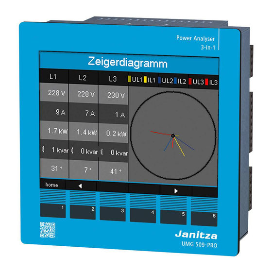
- Page 71 UMG 509-PRO 12. 5. 1 Phasor diagram examples 12. 6 Applying the residual current The following are two examples for Only connect residual current transformers an indication of measured current and with a rated current of 30 mA to inputs...
- Page 72 UMG 509-PRO www.janitza.de 12. 7 Failure monitoring (RCM) 12. 7. 1 Alarm status The device enables continuous monitoring Using bit-by-bit coding inside the alarm of the connection to the residual current register (addr. 19224 for I5, 19225 for I6), transformer on inputs I5 and I6.
- Page 73 UMG 509-PRO 12. 8 Measurement range exceeded If the measurement range is exceeded, it is displayed as long as this persists and cannot be acknowledged. The measurement range is exceeded if at least one of the four voltage or current measurement inputs lies outside their specified measuring range.
- Page 74 UMG 509-PRO www.janitza.de 12. 11 Communication in the bus system Designation Hex Comment 12. 11. 1 RS485 Device Address=1 The MODBUS RTU protocol with CRC address check on the RS485 interface can be used Function “Read Holding Reg” to access the data from the parameter and the measured value lists (see “11.
- Page 75 The device master file for your device has the file name "U5090F15.GSD" and You can use the Profibus profile to: is available on the Janitza homepage. Variable definition • retrieve measured values from the UMG, • set the digital outputs in the UMG, All system variables and global variables •...
- Page 76 Profibus PLC process input box 1. Byte = Return signal from the profile number Profile number Measured values 2. Byte = Data requested by UMG 509-PRO Data • • Fig. Block diagram for data exchange between PLC and UMG 509-PRO.
- Page 77 UMG 509-PRO Factory pre-configured profiles This section provides you with a tabular overview of the pre-configured Profibus profiles • Profibus profile number 0 Byte Value type Value Scaling index format Voltage L1-N Float Voltage L2-N Float Voltage L3-N Float...
- Page 78 UMG 509-PRO www.janitza.de • Profibus profile number 1 Byte Value type Value Scaling index format Voltage L1-N Float Voltage L2-N Float Voltage L3-N Float Voltage L2-L1 Float Voltage L3-L2 Float Voltage L1-L3 Float Current L1 Float Current L2 Float Current L3...
- Page 79 UMG 509-PRO • Profibus profile number 2 Byte Value type Value Scaling index format Total active energy L1-L3 Float Rel. Total active energy L1-L3 Float Deliv. Total active energy L1-L3 Float Total reactive energy L1-L3 Float Ind. Total reactive energy L1-L3 Float Total cap.
- Page 80 UMG 509-PRO www.janitza.de 12. 11. 3 Recording configuration 2 recordings are pre-configured in the de- vice’s factory default setting. Recordings are adjusted and expanded using the GridVis® software. Profile Measured Value Time base Type Voltage effective 15 min mean value (arithmetic), L1,L2, L3, L4, L1-L2, L2-L3, L3-L1 min.-/max.-value...
- Page 81 UMG 509-PRO...
- Page 82 • The value type that the incoming signal has. • The scaling factor that is to be used for the value. Fig. Configuring the UMG 509-PRO digital outputs via GridVis®. Fig. Configuring the UMG 509-PRO inputs via GridVis®.
- Page 83 UMG 509-PRO Pulse length Pulse value The pulse length applies to both pulse The pulse value is used to indicate how much outputs and is set using the GridVis® power (Wh or varh) should correspond to software. a pulse.
- Page 84 UMG 509-PRO www.janitza.de Determine the pulse value Measurement errors when 1. Set the pulse length in accordance with using as a pulse output CAUTION! the requirements of the connected pulse receiver. For example, if the pulse length When using the digital outputs as pulse...
- Page 85 UMG 509-PRO...
- Page 86 UMG 509-PRO www.janitza.de Device homepage Your measurement device has an integrated You can do the following here without first web server, which has a separate homepage. installing any software: You can use this device home page to • call historical and current measured access your measurement device from any values.
- Page 87 UMG 509-PRO 13. 1 Measured values You can use the “Measured values” menu item to call simple and detailed views of the measured values, and to display individual measured values. The following menu items are available: • Short overview •...
- Page 88 UMG 509-PRO www.janitza.de 13. 1. 2 Detailed measured values In the overview, you can call extensive information on the following points: • Voltage • Current • Power • Harmonic oscillations • Energy • Peripheral devices (digital inputs/outputs, temperature measurements) Fig. Detailed overview of measured values...
- Page 89 UMG 509-PRO 13. 1. 3 Diagrams You can use the “Diagrams” item to access the measured values monitor. The measured values monitor is a configurable display of current and historical measured values with automatic scaling. In order to display a graphic of the measured values, drag the required values from the list on the left edge of the screen into the field in the middle of the screen.
- Page 90 UMG 509-PRO www.janitza.de 13. 1. 5 Events You can use the “Events” item to call a graphical illustration of the recorded events such as overcurrent or undervoltage. For more information on event recording, see “11. 3. 3 Events”. Fig. Event records 13.
- Page 91 UMG 509-PRO 13. 2 Power quality The “Power quality” section (PQ) provides you with the option of calling the PQ status in a clear way according to common standards. Here, you have access to permanent power quality monitoring in accordance with: •...
- Page 92 13. 3. 1 Push Service The push service is an example of an installable app. The push service sends measured val- ues directly from the device to a cloud or portal solution chosen by you, such as the Janitza Energy Portal.
- Page 93 You can control the device remotely here by clicking the control buttons using the mouse. Fig. Operating the UMG 509-PRO via the device homepage 13. 4. 3 Downloads You can use the “Downloads” item to access the download area on the Janitza homepage. You can download catalogues and operation manuals from here.
- Page 94 UMG 509-PRO www.janitza.de Service and maintenance The device underwent various safety checks 14. 5 Device calibration before delivery and is marked with a seal. The devices are calibrated by the manufacturer If a device is open, the safety checks must at the factory - it is not necessary to recalibrate be repeated.
- Page 95 UMG 509-PRO 14. 8 Battery The internal clock is fed from the supply voltage. If the supply voltage fails then the clock is powered by the battery. The clock provides date and time information, for the records, min. and max.
- Page 96 UMG 509-PRO www.janitza.de Procedure in the event of faults Possible fault Cause Remedy No display External fuse for the power Replace fuse. supply voltage has tripped. No current display Measured voltage Connect the measured voltage. isnotconnected. Measurement current Connect measuring-circuit isnotconnected.
- Page 97 UMG 509-PRO Possible fault Cause Remedy Active power too high The programmed CT ratio Read out and program the CT or too low. is incorrect. ratio on the current transformer The current circuit is assigned Check connection and correct to the wrong voltage circuit.
- Page 98 UMG 509-PRO www.janitza.de Technical data General Net weight (with attached connectors) approx. 1080 g (2.38 lb) Device dimensions approx. l = 144 mm (5.64 in), w = 144 mm (5.64 in), h = 75 mm (2.95 in) Battery type Li-Mn CR2450, 3V (approval i.a.w. UL 1642) Clock - in temperature range -40°C (-40 °F)
- Page 99 UMG 509-PRO 16. 2 Voltage and current measurement Current measurement Rated current Resolution 0.1 mA Metering range 0.005 to 7 Amps Measurement range exceeded (overload) as of 7.5 Amps Crest factor Overvoltage category 230 V option: 300 V CAT III...
- Page 100 UMG 509-PRO www.janitza.de Terminal connection capacity (voltage and current measurement) Connectable conductors. Only one conductor can be connected per terminal! Single core, multi-core, fine-stranded 0.2 - 2.5 mm , AWG 24-12 Terminal pins, core end sheath 0.25 - 2.5 mm Tightening torque 0.5 - 0.6 Nm...
- Page 101 UMG 509-PRO 16. 4 Temperature measurement input Temperature measurement input 3-wire measurement Update time 1 second Connectable sensors PT100, PT1000, KTY83, KTY84 Total burden (sensor + cable) max. 4 kOhm Cable length up to 30 m (32.81 yd) unshielded, from 30 m (32.81 yd) shielded...
- Page 102 UMG 509-PRO www.janitza.de 16. 5 Digital inputs and outputs Digital inputs 2 Digital inputs with a joint earth Maximum counter frequency 20 Hz Response time (Jasic program) 200 ms Input signal present 18 V to 28 V DC (typical 4 mA) Input signal not present 0 to 5 V DC, current less than 0.5 mA...
- Page 103 UMG 509-PRO 16. 6 Interfaces RS485 interface 3-wire connection with GND, A, B Protocol Modbus RTU/slave, Modbus RTU/master, Modbus RTU /gateway Transmission rate 9.6 kbps, 19.2 kbps, 38.4 kbps, 57.6 kbps, 115.2 kbps, 921.6 kbps Termination resistor can be activated by micro switch...
- Page 104 5 minutes in case the operating voltage fails: · Comparator timer · S0 counter statuses · Min. / Max. / mean values (without the date and time) · Energy values Configuration data is saved immediately. A detailed Modbus address and parameter list can be found at www.janitza.com...
- Page 105 UMG 509-PRO 16. 8 Dimension diagrams Fig. View from the side Fig. View from below...
- Page 106 UMG 509-PRO www.janitza.de Menu guide overview 17. 1 Configuration menu overview Additional main values Display Display Display Communication Home Voltage L-N Status (Measured value overview) Additional main values (config) Configuration Language, communication, measurement, system Display, colours, extensions Measurement Display System...
- Page 107 UMG 509-PRO 17. 2 Overview of measured value indications Main values Device name Voltage Current Active power Active energy Overview L1 to L4 L1 to L3 Overview (Active power) (Tariff 1, tariff 2) Measured values (config) Configuration Voltage Residual current...
- Page 108 UMG 509-PRO www.janitza.de Main values Active energy Harmonics Voltage Transients Events Monthly values Voltage L1 progression L1 1 to 8 1 to 8 Bar diagram (L2, L3, L4) (L2, L3, L4) (9 to 16) (9 to 16) Apparent energy Harmonics...
- Page 109 UMG 509-PRO Main values Phasor Oscilloscope Communication diagram status Oscilloscope Oscilloscope ULN1 to 3 ULN1 to 4 Oscilloscope IL1 to 3 IL1 to 4 Fig. Schematic illustration of the menu guide for the measured value indications, part 3...
- Page 110 Temp. Digital Digital Outputs Inputs UMG 509-PRO Hilfsenergie Strommessung 1-4 Spannungsmessung 1-4 Auxiliary Supply Current Input 1-4 Voltage Input 1-4 L/+ N/- 19 20 21 22 23 24 25 26 Fig. Schematic drawing of connection example for the UMG 509-PRO...
- Page 111 UMG 509-PRO...