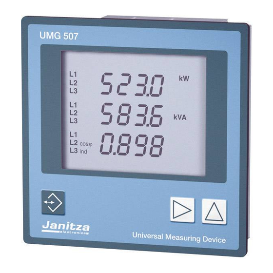
janitza UMG507 Functional Description
Universal measuring device
Hide thumbs
Also See for UMG507:
- Installation and initial startup (48 pages) ,
- Functional description (24 pages)
Summary of Contents for janitza UMG507
- Page 1 Universal Measuring Device UMG507 Functional description Profibus DP V0 Janitza electronics GmbH Vor dem Polstück 1 35633 Lahnau Support Tel. (06441) 9642-22 email: info@janitza.de internet: http://www.janitza.de...
- Page 2 Generals The UMG507 supports the protocols Modbus RTU, Modbus TCP/IP, Modbus over TCP/IP (Modbus Gateway) or Profibus DP V0, depending in the version. This functional description is an addition to the manual and describes the configuration of the corresponding function step by step.
- Page 3 . T he certified Profibus instrument UMG507P/EP supports Profibus DP V0 up to 1,5Mbaud. The Profibus connection of the UMG507 is carried out as 9 pole Sub Dplug ausgeführt. For connection, we recommend a 9 pole Profibus plug (Type: SUBCON-PLUS-ProfiB/AX/SC Manufacturer: Phoenix part no.: 27 44 38 0 or similar).
- Page 4 The following four profiles are unchangeable set in the manufacturer’s settings: Profile 0 (high before low byte) Profile 1(high before low byte) Format : Float 4 Byte unit Format : Float 4 Byte unit Reactive power Phase: L1 Voltage Phase: L1 Reactive power Phase: L2 Voltage Phase: L2 Reactive power Phase: L3...
-
Page 5: Device Address
PLC. The GSD file of the UMG507P/EP can be found on the CD-ROM PSWbasic/professional or in the Downlaod area on our homepage (www.janitza.de). The GSD file of the UMG507P/EP supports the following modules: "STD: 16 Word In, 1 Byte Out"... -
Page 6: Protocol Setting
Protocol setting The RS485 interface of the UMG507P/EP is suitable for transmission of data over a distance up to 1200m. Up to 31 UMG507P/EP and a master (PC/PLC) can be connected. The RS485 interface of UMG507P/EP supports several protocols, which can be selected directly at the device. Transmission protocols RS485 Display RS485 interface 0 = Modbus RTU Slave... -
Page 7: Creating New Profiles
Install the software PSWbasic/professional on your PC. After starting the software go to menu „Configuration Software“, „Define measuring devices“. Connect the delivered RS232 interface cable to the RS 232 interface of the UMG507 and define the device within the software. - Page 8 Open the menu „Configure Profiles for Profibus“ in menu UMG507. The first four profiles are not changeable. 20 user defined profiles can be created. Select the profile „user defined 1“ from the list. On the right side the possible measured values can be found.
- Page 9 For each user defined profile up to 64 entries are possible. The parameter number provides the internal register address (see address list UMG507). Transmit the profile to the UMG507P/ Save the profile in a file and transmit it to the device (Send configuration to...
- Page 10 For integer values, the scale must be set additionally. Go to menu „Configure UMG507“ and enter panel „Method of measurement“. After changing the scaling, it must be transmitted to the UMG507P/ EP as well. The solution or scaling must be chosen in a way, that the range of the integer format (e.g. - 32768 to 32767) is not exceeded.
- Page 11 The energy is always transmitted with the unit kWh. Using the format LONG at scale *1, the transmission value is limited to 2147 GWh. But the display range of UMG507 is up to 9999GWh. The scale factor depends on the power of the panel.
-
Page 12: Control Value
2. Example integer format Automatically given E-address range for UMG507E/EP with device address 1: 256 ... 307 Selected profile: 32 (user defined profile 1) selected format integer The structure is as follows: Operand Symbol Status format Status value Control value Input: PAB 256 // Profile number... - Page 13 The internal clock shall be synchronized via Profibus flag 1 for the next full hour, and additionally, the Profibus flag 2 deletes the energy counter for real power. At first, install a UMG 507 P/EP in software PSWbasic/professional as written in chapter „Create new profiles“. Change to menu „Configure UMG507“ into window „output channels“. Assign output channel 1 to the target function „set clock“...
- Page 14 Profibus. At first, install a UMG 507 P/EP in software PSWbasic/professional as written in chapter „Create new profiles“. Change into menu „Configure UMG507“ into window „Trigger events“. Select the corresponding phase in the Drop Down Field and set the limit for low voltage.
- Page 15 Example 3: Analogue output The control of the analogue output is carried out via the 3. and 4. or 4. and 5 Byte in the output range. Die Daten werden fest auf die Parameter 9000 bzw. 9002 geschrieben. Configure the analogue outputof the UMG507P/EP to the parameters 9000 or 9002 and set the scale for the scale starting value and scale end value.


