
Related Manuals for Makita XSL08


Summary of Contents for Makita XSL08
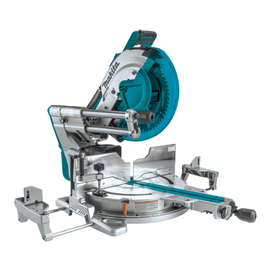
- Page 1 INSTRUCTION MANUAL MANUAL DE INSTRUCCIONES Cordless Slide Compound Miter Saw Sierra de Inglete Inalámbrica XSL08 XSL07 IMPORTANT: Read Before Using. IMPORTANTE: Lea antes de usar.
- Page 2 ENGLISH (Original instructions) SPECIFICATIONS Model: XSL08 XSL07 Blade diameter 305 mm (12″) Hole diameter 25.4 mm (1″) Max. kerf thickness of the saw blade 3.2 mm (1/8″) Max. miter angle Right 60°, Left 60° Max. bevel angle Right 48°, Left 48°...
- Page 3 Applicable battery cartridge and charger Battery cartridge BL1815N / BL1820B / BL1830 / BL1830B / BL1840B / BL1850B / BL1860B Charger DC18RC / DC18RD / DC18RE / DC18SD / DC18SE / DC18SF • Some of the battery cartridges and chargers listed above may not be available depending on your region of residence.
- Page 4 Always wear protective goggles to protect your Under abusive conditions, liquid may be eyes from injury when using power tools. The ejected from the battery; avoid contact. If con- goggles must comply with ANSI Z87.1 in the USA. tact accidentally occurs, flush with water. If It is an employer's responsibility to enforce the liquid contacts eyes, additionally seek medical use of appropriate safety protective equipment...
- Page 5 Never cross your hand over the intended line 13. Do not use another person as a substitute for of cutting either in front or behind the saw a table extension or as additional support. blade. Supporting the workpiece "cross handed" Unstable support for the workpiece can cause the i.e.
- Page 6 23. Some material contains chemicals which may Do not operate saw without guards in place. Check blade guard for proper closing before be toxic. Take caution to prevent dust inhala- each use. Do not operate saw if blade guard tion and skin contact. Follow material supplier does not move freely and close instantly.
- Page 7 16. Always close the lid of the slot when causing fires, personal injury and damage. It will operating. also void the Makita warranty for the Makita tool and 17. Do not remove the wireless unit from the slot charger. while the power is being supplied to the tool.
- Page 8 SAVE THESE INSTRUCTIONS. 26. Do not insert any devices other than Makita wireless unit into the slot on the tool. 27. Do not use the tool with the lid of the slot dam- aged.
- Page 9 Guide fence (lower elevation) extraction) fence) fence) Switch trigger Lock-off button Hole for padlock Lid (for wireless unit) (For XSL08 only) Switch (for laser line) Battery indicator Mode indicator Check button Wireless activation Wireless activation lamp Dust bag Bevel angle scale button 0°...
- Page 10 Installing the dust extraction hose Bench mounting Connect the dust extraction hose to the tool as When the tool is shipped, the handle is locked in the illustrated. lowered position by the stopper pin. While lowering the Make sure that the elbow and the sleeve fit properly to handle slightly, pull the stopper pin and rotate it 90°.
- Page 11 Overload protection FUNCTIONAL DESCRIPTION When the tool is operated in a manner that causes it to draw an abnormally high current, the tool automatically WARNING: Always be sure that the tool is stops without any indication. In this situation, turn the switched off and the battery cartridge is removed tool off and stop the application that caused the tool to before adjusting or checking the functions on...
- Page 12 Indicating the remaining battery capacity Mode indicator status Operation mode Only for battery cartridges with the indicator High speed mode High torque mode This tool has "high speed mode" and "high torque mode". It automatically changes operation mode depending on the work load. When mode indicator lights up during operation, the tool is in high torque mode.
- Page 13 Do not remove spring holding blade guard. If guard becomes discolored through age or UV light exposure, contact a Makita service center for a new guard. DO NOT DEFEAT OR REMOVE GUARD. ► 1. Left bevel cut 2. Straight cut 3. Right bevel cut 4.
- Page 14 Push the carriage toward the guide fence fully and WARNING: After installing a new blade and lower the handle completely. with the batteries removed, always be sure that Adjust the blade position by turning the adjusting bolt the blade does not contact any part of the lower with the hex wrench.
- Page 15 Adjusting the miter angle Adjusting the bevel angle NOTICE: Always remove the upper guide fences CAUTION: After changing the miter angle, and vertical vise before adjusting the bevel angle. always secure the turn base by tightening the grip firmly. NOTICE: When changing bevel angles, be sure to position the kerf boards appropriately as NOTICE:...
- Page 16 Match the pointer with your desired angle on the If you perform a bevel cut greater than 45°, move the scale by moving the carriage then tighten the knob. carriage while sliding the releasing lever toward the front of the tool. You can perform up to 48° bevel cut. ►...
- Page 17 A switch in need of repair may result in unintentional operation and serious personal injury. Return tool to a Makita service center for proper repairs BEFORE further usage. ► 1. Switch for laser ►...
- Page 18 Accidental start up of the tool may result in serious personal injury. WARNING: Use only the Makita wrench pro- vided to install or remove the saw blade. Failure to use the wrench may result in overtightening or insuf- ficient tightening of the hex socket bolt and serious personal injury.
- Page 19 Always lock the carriage with raised position when Press the shaft lock to lock the spindle and use the hex removing and installing the saw blade. Pull the stopper wrench to loosen the hex socket bolt. Then remove the pin and rotate it 90° with the carriage raised. hex socket bolt, outer flange and saw blade.
- Page 20 Connecting a vacuum cleaner When you wish to perform clean cutting operation, con- nect a Makita vacuum cleaner to the dust nozzle using a front cuff 24 (optional accessory). ► 1. Fastener ► 1. Front cuff 24 2. Hose 3. Vacuum cleaner...
- Page 21 Use upper fences to support the material higher than Securing workpiece the lower fences. Insert the upper fence into the hole on the lower fence and tighten the clamping screw. WARNING: It is extremely important to always secure the workpiece correctly with the proper type of vise or crown molding stoppers.
- Page 22 Vertical vise NOTE: For a quick setting of workpiece, turning the vise knob to 90° counterclockwise allows the vise knob to be moved up and down. To secure the work- WARNING: The workpiece must be secured piece after setting, turn the vise knob clockwise. firmly against the turn base and guide fence with the vise during all operations.
- Page 23 — Aluminum products avoid blade pinch and possible kickback which may Refer to our website or contact your local Makita dealer result in serious personal injury. for the correct circular saw blades to be used for the material to be cut.
- Page 24 Press cutting WARNING: Always lock the sliding movement of the carriage when performing a press cutting. Cutting without lock may cause possible kickback which may result in serious personal injury. Workpieces up to 92 mm (3-5/8") high and 183 mm (7-1/4") wide can be cut in the following manner.
- Page 25 Bevel cut Compound cutting Compound cutting is the process in which a bevel WARNING: After setting the blade for a bevel angle is made at the same time in which a miter angle cut, ensure that the carriage and saw blade will is being cut on a workpiece.
- Page 26 Measuring Cutting crown and cove moldings Measure the wall width, and adjust the width of the Crown and cove moldings can be cut on a compound workpiece according to it. Always make sure that width miter saw with the moldings laid flat on the turn base. of the workpiece's wall contact edge is the same as wall There are two common types of crown moldings and length.
- Page 27 Table (B) Table (B) – Molding Molding Finished – Molding Molding Finished position in edge against piece position in edge against piece the figure guide fence the figure guide fence For inside Ceiling Finished For inside Wall contact Finished corner contact edge piece will be corner...
- Page 28 Miter and Bevel Angle Settings Wall to Crown Molding Angle: 52°/38° 43.0 46.8 30.1 26.9 15.3 12.3 42.8 46.3 29.7 26.5 14.9 12.0 42.5 45.7 29.4 26.1 14.5 11.6 42.2 45.1 29.0 25.7 14.1 11.3 41.9 44.6 28.7 25.3 13.7 11.0 41.7 44.0...
- Page 29 Wall to Crown Molding Angle: 45° 37.8 50.8 26.7 30.2 13.7 14.1 37.5 50.2 26.4 29.8 13.3 13.7 37.3 49.6 26.1 29.4 13.0 13.3 37.1 49.1 25.8 28.9 12.6 12.9 36.8 48.5 25.5 28.5 12.3 12.6 36.6 48.0 25.2 28.1 11.9 12.2 36.4...
- Page 30 Crown molding stopper Position crown molding with its WALL CONTACT EDGE against the guide fence and its CEILING CONTACT Optional accessory EDGE against the crown molding stoppers as shown in the figure. Adjust the crown molding stoppers according Crown molding stoppers allow easier cuts of crown to the size of the crown molding.
- Page 31 Cut a platform to the dimensions indicated in the Cutting aluminum extrusion figure using a 38 mm (1-1/2″) thick, flat stock material such as wood, plywood or particle board. ► 1. 0° Miter angle: Over 450 mm (17-3/4″) 2. 45° Miter angle: Over 325 mm (12-3/4″) 3.
- Page 32 Install both the upper fences on the tool. For a dado type cut, perform as follows: Adjust the lower limit position of the saw blade WARNING: Do not use the tool without upper using the adjusting screw and the stopper arm to limit fences installed.
- Page 33 WIRELESS ACTIVATION FUNCTION ► 1. Hole 2. Over 15 mm (9/16″) 3. Over 270 mm (10- For XSL08 only 5/8″) 4. 90 mm (3-1/2″) 5. 145 mm (5-3/4″) 6. 19 mm What you can do with the wireless (3/4″) 7. 115 - 120 mm (4-1/2″ - 4-3/4″) activation function EXAMPLE When cutting workpieces 115 mm (4-1/2")
- Page 34 When inserting the wireless unit, align the projections cleaner with the recessed portions on the slot. NOTE: A Makita vacuum cleaner supporting the wireless activation function is required for the tool registration. NOTE: Finish installing the wireless unit to the tool before starting the tool registration.
- Page 35 Set the stand-by switch on the vacuum cleaner to NOTE: The wireless activation lamps finish blinking "AUTO". in green after 20 seconds elapsed. Press the wireless activation button on the tool while the wireless acti- vation lamp on the cleaner is blinking. If the wireless activation lamp does not blink in green, push the wire- less activation button briefly and hold it down again.
- Page 36 Push the wireless activation button on the tool Pull the switch trigger of the tool. Check if the briefly. The wireless activation lamp will blink in blue. vacuum cleaner runs while the switch trigger is being pulled. To stop the wireless activation of the vacuum cleaner, push the wireless activation button on the tool.
- Page 37 If the cancellation is performed successfully, the wire- Cancelling tool registration for the less activation lamps will light up in red for 2 seconds vacuum cleaner and start blinking in blue. NOTE: The wireless activation lamps finish blinking in Perform the following procedure when cancelling the red after 20 seconds elapsed.
- Page 38 Before asking for repairs, conduct your own inspection first. If you find a problem that is not explained in the manual, do not attempt to dismantle the tool. Instead, ask Makita Authorized Service Centers, always using Makita replace- ment parts for repairs.
- Page 39 To maintain product SAFETY and RELIABILITY, repairs, any other maintenance or adjustment should ► 1. Triangular rule be performed by Makita Authorized or Factory Service Centers, always using Makita replacement parts. Bevel angle Adjusting the cutting angle 0°...
- Page 40 Carefully square the side of the saw blade with the top If the pointer does not indicate the 45° position, align surface of the turn base using the triangular rule, try- it with 45° position by turning the adjusting bolt on the square, etc.
- Page 41 NOTICE: Have the tool repaired by a Makita authorized service center for any failure on the laser unit. The movable range of laser line is decided by the range adjustment screws on both sides.
- Page 42 Lubricate the sliding portions with machine oil to prevent rust. OPTIONAL ACCESSORIES WARNING: These Makita accessories or attach- ments are recommended for use with your Makita tool specified in this manual. The use of any other accesso- ries or attachments may result in serious personal injury. WARNING: Only use the Makita accessory or attachment for its stated purpose.
- Page 43 ESPAÑOL (Instrucciones originales) ESPECIFICACIONES Modelo: XSL08 XSL07 Diámetro del disco 305 mm (12″) Diámetro del orificio 25,4 mm (1″) Ancho de corte máx. del disco de la sierra 3,2 mm (1/8″) Ángulo de inglete máximo Derecho 60°, Izquierdo 60° Ángulo de bisel máximo Derecho 48°, Izquierdo 48°...
- Page 44 Cartucho de batería y cargador aplicables Cartucho de batería BL1815N / BL1820B / BL1830 / BL1830B / BL1840B / BL1850B / BL1860B Cargador DC18RC / DC18RD / DC18RE / DC18SD / DC18SE / DC18SF • Algunos de los cartuchos de batería y cargadores enumerados arriba podrían no estar disponibles depen- diendo de su área de residencia.
- Page 45 Retire cualquier llave de ajuste o llave de Mantenga las herramientas de corte limpias apriete antes de encender la herramienta. Una y filosas. Si recibe un mantenimiento adecuado llave de ajuste o llave de apriete que haya sido y tiene los bordes afilados, es probable que la dejada puesta en una parte giratoria de la herra- herramienta se atasque menos y sea más fácil mienta eléctrica puede ocasionar alguna lesión.
- Page 46 Servicio Haga que una persona calificada repare la herramienta eléctrica utilizando sólo piezas de repuesto idénticas. Esto asegura que se man- tenga la seguridad de la herramienta eléctrica. Nunca dé servicio a baterías que estén daña- das. El servicio a las baterías solamente deberá ser efectuado por el fabricante o un agente de servicio autorizado.
- Page 47 12. Proporcione un apoyo adecuado, tal como exten- 23. La sierra puede cortar madera, aluminio o siones para la mesa, caballetes de aserrado, etc. materiales similares siempre que se utilice un para las piezas de trabajo más anchas o largas disco de la sierra apropiado para el material.
- Page 48 13. Tenga cuidado de no dañar el eje, las bridas Símbolos (especialmente la superficie de instalación) ni el perno. Los daños en estas piezas podrían A continuación se muestran los símbolos utilizados provocar la ruptura del disco. para la herramienta. 14.
- Page 49 Asimismo, esto inva- 15. No oprima el botón de activación inalámbrica en lidará la garantía de Makita para la herramienta y el la unidad inalámbrica demasiado fuerte, ni lo haga cargador Makita. con ningún objeto que tenga un borde filoso.
- Page 50 DESCRIPCIÓN DE LAS PIEZAS Soporte de corredera Clavija de retención Prensa vertical Botón de liberación (para el deslizamiento (para el ángulo de bisel del carro) del lado derecho) Base inferior Base giratoria Marcador (para el Escala del ángulo de ángulo de inglete) inglete Panel de corte Caja del disco...
- Page 51 Gatillo interruptor Botón de desbloqueo Orificio para el candado Tapa (para la unidad inalámbrica) (Para el modelo XSL08 únicamente) Interruptor (para la línea Indicador de batería Indicador de modo Botón de verificación de láser) Botón de activación...
- Page 52 Instalación de la manguera de Montaje en un banco de trabajo extracción de polvo Cuando la herramienta sale de fábrica, la empuñadura es bloqueada en la posición hacia abajo por la clavija Conecte la manguera de extracción de polvo a la herra- de retención.
- Page 53 Sistema de protección para la DESCRIPCIÓN DEL herramienta/batería FUNCIONAMIENTO La herramienta está equipada con un sistema de pro- tección de la herramienta/batería. Este sistema corta ADVERTENCIA: Asegúrese siempre de que en forma automática el suministro de energía al motor la herramienta esté apagada y el cartucho de para prolongar la vida útil de la herramienta y la batería.
- Page 54 NOTA: Dependiendo de las condiciones de uso y Estado del indicador de batería Capacidad restante de la la temperatura ambiente, la indicación podrá diferir batería ligeramente de la capacidad real. Encendido Apagado Parpadeando Función de cambio de velocidad automática 50% a 100% 20% a 50% 0% a 20% Cargar la...
- Page 55 No quite el resorte que sujeta el protector del disco. Si el protector llega a decolorarse con el tiempo o por la exposición a luz ultravioleta, póngase en contacto con un centro de servicio Makita para solicitar un protector nuevo. NO INHABILITE NI RETIRE EL PROTECTOR.
- Page 56 Mantenimiento de la capacidad máxima de corte Esta herramienta está ajustada de fábrica para ofrecer la máxima capacidad de corte para un disco de la sierra de 305 mm (12″). Al instalar un disco nuevo, revise siempre la posición del límite inferior del disco y, de ser necesario, haga el ajuste como se indica a continuación: Primero, retire las baterías.
- Page 57 Brazo de retención La posición del límite inferior del disco puede ser ajustada fácilmente con el brazo de retención. Para ajustarla, gire el brazo de retención en la dirección de la flecha tal como se muestra en la figura. Gire el tornillo de ajuste de manera que el disco se detenga en la posi- ción deseada al bajar por completo la empuñadura.
- Page 58 Gire el pomo en el soporte de corredera en sen- Ajuste el marcador en el ángulo que desee en la tido inverso al de las manecillas del reloj. escala moviendo el carro y luego apriete el pomo. ► 1. Pomo Jale y gire la palanca de la aldabilla a la posición que se muestra en la ilustración.
- Page 59 El uso de un interruptor que requiere reparación puede ocasionar una operación accidental y lesiones personales graves. Lleve la herramienta a un centro de servicio Makita para las reparaciones apropiadas ANTES de continuar su uso. 59 ESPAÑOL...
- Page 60 Si la herramienta falla constantemente en detener el disco tras soltar el gatillo interruptor, lleve la herramienta a mantenimiento a un centro de servicio Makita. PRECAUCIÓN: El sistema de frenado del disco no es un substituto del protector del disco.
- Page 61 ADVERTENCIA: Utilice únicamente la llave suministrada por Makita para instalar o extraer el disco de la sierra. El no utilizar la llave podría ocasionar un apriete excesivo o insuficiente del perno de cabeza hexagonal y provocar lesiones personales graves.
- Page 62 Bloquee siempre el carro con la posición levantada Presione el bloqueo del eje para bloquear el eje y use la cuando extraiga e instale el disco de la sierra. Jale la llave hexagonal para aflojar el perno de cabeza hexa- clavija de retención y gírela 90°...
- Page 63 Conexión de una aspiradora Cuando desee realizar una operación de corte limpia, conecte una aspiradora Makita a la boquilla para polvo usando los manguitos delanteros 24 (accesorios opcionales). ► 1. Cierre ► 1. Manguitos delanteros 24 2. Manguera 3.
- Page 64 Utilice las guías superiores para apoyar el material más Aseguramiento de la pieza de arriba de las guías inferiores. Inserte la guía superior trabajo en el orificio de la guía inferior y apriete el tornillo de fijación. ADVERTENCIA: Es sumamente importante asegurar siempre la pieza de trabajo de manera correcta usando un tipo adecuado de prensa o topes para moldura de corona.
- Page 65 Presione la pieza de trabajo en forma horizontal contra Prensa vertical la guía lateral y la base giratoria. Coloque la pieza de trabajo en la posición de corte deseada y asegúrela con ADVERTENCIA: firmeza ajustando el seguro de la prensa. La pieza de trabajo deberá...
- Page 66 228 mm (9″). Esta herramienta está diseñada para cortar productos de madera. Con los discos de la sierra apropiados Base inferior y originales de Makita también se pueden cortar los siguientes materiales: ADVERTENCIA: Apoye siempre una pieza de —...
- Page 67 Las piezas de trabajo de hasta 92 mm (3-5/8″) de alto y 183 mm (7-1/4″) de ancho pueden ser cortadas de la siguiente manera. ► 1. Clavija de retención Empuje el carro hacia la guía lateral hasta que se detenga y bloquéelo con la clavija de retención. ►...
- Page 68 Una vez finalizado el corte, apague la herramienta Corte en bisel y espere hasta que el disco se haya detenido por completo antes de regresar el disco a su posición ADVERTENCIA: completamente elevada. Una vez que haya ajustado el disco para realizar un corte en bisel, asegúrese Corte compuesto de que el carro y el disco de la sierra puedan des- plazarse libremente a través del rango completo...
- Page 69 Medición Corte de molduras corona y cóncava Mida el ancho de la pared y ajuste la anchura de la pieza de trabajo de acuerdo con éste. Siempre ase- gúrese de que el ancho del borde de contacto con la Las molduras corona y cóncava pueden ser cortadas pared de la pieza de trabajo sea el mismo que la longi- con una sierra de inglete telescópica, colocando las tud de la pared.
- Page 70 Tabla (B) Tabla (A) – Posición de Borde de Pieza – Posición Ángulo de bisel Ángulo de inglete la moldura la moldura terminada de la Tipo de Tipo Tipo de Tipo en la figura contra la moldura 52/38° de 45° 52/38°...
- Page 71 Ajustes del ángulo de inglete y de bisel De la pared al ángulo de la moldura corona: 52°/38° 43.0 46.8 30.1 26.9 15.3 12.3 42.8 46.3 29.7 26.5 14.9 12.0 42.5 45.7 29.4 26.1 14.5 11.6 42.2 45.1 29.0 25.7 14.1 11.3 41.9...
- Page 72 De la pared al ángulo de la moldura corona: 45° 37.8 50.8 26.7 30.2 13.7 14.1 37.5 50.2 26.4 29.8 13.3 13.7 37.3 49.6 26.1 29.4 13.0 13.3 37.1 49.1 25.8 28.9 12.6 12.9 36.8 48.5 25.5 28.5 12.3 12.6 36.6 48.0 25.2...
- Page 73 Tope para moldura de corona Coloque la moldura de corona con el BORDE DE CONTACTO CON LA PARED apoyado contra la guía Accesorio opcional lateral y el BORDE DE CONTACTO CON EL TECHO apoyado contra los topes para moldura de corona tal Los topes para moldura de corona permiten cortar más como se muestra en la ilustración.
- Page 74 Corte una plataforma en las dimensiones que se Corte de extrusión de aluminio indican en la ilustración usando un material plano de 38 mm (1-1/2″) de grueso, tal como madera, madera con- trachapada o madera prensada. ► 1. Ángulo de inglete de 0°: Más de 450 mm (17- 3/4″) 2.
- Page 75 Corte de ranuras ADVERTENCIA: Asegúrese de que la plata- forma esté colocada de manera plana contra la base de la herramienta y firmemente asegurada a las guías ADVERTENCIA: No intente realizar este tipo inferiores usando los cuatro orificios suministrados de corte al usar un tipo de disco más ancho o para los tornillos.
- Page 76 Transporte de la herramienta PRECAUCIÓN: Use una pieza recta de madera con un grueso uniforme para el elemento Antes de transportar la herramienta, cerciórese de auxiliar de madera. retirar las baterías y que todas las piezas móviles de la PRECAUCIÓN: Para poder cortar completa- sierra de inglete estén aseguradas.
- Page 77 Abra la tapa en la herramienta tal como se mues- FUNCIÓN DE ACTIVACIÓN tra en la ilustración. INALÁMBRICA Para el modelo XSL08 únicamente Lo que puede hacer con la función de activación inalámbrica La función de activación inalámbrica permite una ope- ración limpia y cómoda.
- Page 78 Registro de la herramienta para la aspiradora NOTA: Para el registro de la herramienta, se requiere una aspiradora Makita compatible con la función de activación inalámbrica. NOTA: Termine de instalar la unidad inalámbrica en la herramienta antes de comenzar con el registro de la herramienta.
- Page 79 Oprima el botón de activación inalámbrica en la NOTA: Las luces indicadoras de activación inalám- herramienta durante un lapso breve. La luz indicadora brica terminarán parpadeando en verde después de de activación inalámbrica parpadeará en azul. un lapso de 20 segundos. Oprima el botón de acti- vación inalámbrica en la herramienta mientras la luz indicadora de activación inalámbrica en la aspiradora esté...
- Page 80 Descripción del estado de la luz indicadora de activación inalámbrica ► 1. Luz indicadora de activación inalámbrica La luz indicadora de activación inalámbrica muestra el estado de la función de activación inalámbrica. Consulte la tabla a continuación para ver qué significa el estado de la luz indicadora. Estado Luz indicadora de activación inalámbrica Descripción...
- Page 81 Si la cancelación se realiza exitosamente, las luces Cancelación del registro de la indicadoras de activación inalámbrica se encenderán herramienta para la aspiradora en rojo durante 2 segundos y comenzarán a parpadear en azul. Realice el siguiente procedimiento para cancelar el NOTA: Las luces indicadoras de activación inalám- registro de la herramienta para la aspiradora.
- Page 82 Antes de solicitar alguna reparación, primero realice una inspección por su cuenta. Si detecta algún problema que no esté explicado en el manual, no intente desensamblar la herramienta. En vez de esto, solicite la reparación a un centro de servicio autorizado de Makita, usando siempre piezas de repuesto Makita. Estado de la anomalía Causa probable (avería)
- Page 83 Para mantener la SEGURIDAD y FIABILIDAD del pro- ducto, las reparaciones, y cualquier otra tarea de man- tenimiento o ajuste deberán ser realizadas en centros de servicio autorizados o de fábrica Makita, empleando siempre repuestos Makita. ► 1. Tornillo en el marcador 2. Tornillos en la escala del ángulo de inglete 3.
- Page 84 Ajuste la base giratoria en la posición de 0° usando la Cuadre cuidadosamente el lado del disco de la sierra función de tope de seguridad. Cuadre el lado del disco con la parte superior de la base giratoria usando una con la cara de la guía lateral usando una regla trian- regla triangular, escuadra, etc., y girando el perno de gular o escuadra.
- Page 85 útil. AVISO: Lleve la herramienta a reparar a un cen- tro de servicio autorizado de Makita en caso de haber alguna falla en la unidad láser. El rango móvil de la línea de láser se determina mediante los tornillos de ajuste de rango a ambos lados.
- Page 86 ACCESORIOS OPCIONALES ADVERTENCIA: Estos accesorios o adita- mentos Makita están recomendados para utilizarse con su herramienta Makita que se especifica en este manual. El uso de cualquier otro accesorio o adi- tamento puede ocasionar lesiones personales graves. ADVERTENCIA: Use los accesorios o adi- tamentos Makita solamente para su propósito...
- Page 87 Llave hexagonal • Llave hexagonal (para el ajuste del láser) • Unidad inalámbrica (para el modelo XSL08) • Batería y cargador originales de Makita NOTA: Algunos de los artículos en la lista pueden incluirse en el paquete de la herramienta como acce- sorios estándar.
- Page 88 Para reducir la exposición a estos productos químicos: trabaje en un área bien ventilada y póngase el equipo de seguridad indicado, tal como las máscaras contra polvo que están especialmente diseñadas para filtrar partículas microscópicas. Makita Corporation 3-11-8, Sumiyoshi-cho, Anjo, Aichi 446-8502 Japan 885698-949...