
Related Manuals for Bosch EX40N


Summary of Contents for Bosch EX40N
- Page 1 Precision Engineered Opto-Electronics™ INSTALLATION INSTRUCTIONS EX40N Hi-Impact Dome Night-Vision Camera IMPORTANT SAFETY INSTRUCTIONS MAN-40N-00...
- Page 2 Read these instructions. Keep this instruction. Heed all warnings. Follow all instructions. Do not use this apparatus near water. Clean only with dry cloth. Do not block any ventilation openings. Install in accordance with manufacturer instructions. Do not install near any heat sources such as radiators, heat registers, stoves or other apparatus (including amplifiers) that produce heat.
- Page 3 10. Protect the power cord from being walked on or pinched particularly at plugs, convenience receptacles, and the power where they exit from the apparatus. 11. Only use attachments/accessories specified by the manufacturer. 12. Use only with the cart, stand, tripod, bracket, or table specified by the manufacturer, or sold with the apparatus.
- Page 4 EU Directives covered by this declaration: 72/9/EC Low Voltage Directives 89/336/EEC Electromagnetic Compatibility Directive Bosch Security Systems, Inc. will not be responsible for injuries or damages resulting from the improper installation or use of any product sold by Bosch Security Systems, Inc their agents, distributors or...
- Page 5 PSU box. 3) Contact BOSCH Service Center for further advice.
-
Page 6: Table Of Contents
INDEX – EX40N Page Description...........1 Unpacking............2 Parts List............2 Items Required for Installation.....2 Initial Preparations ........3 Guidelines............3 Section 1. Dome Removal......4 Section 2. Input Power Connections ...6 Section 3. Mounting - Camera Base....9 Section 4. Camera/LED Adjustments ..16 Section 5. Camera Re-Assembly ....21 Section 6. -
Page 7: Description
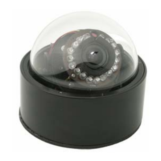
DESCRIPTION The EX40N High Impact Dome Night Vision Camera has been engineered for day/night surveillance in hostile environments. Compact and good looking, the camera features armour- tough construction for protection against vandalism or accidental damage. An aluminum housing, CNC-machined from a... -
Page 8: Unpacking
PARTS LIST (items supplied with unit) - Camera Assembly - Installation Instructions booklet - EX40N Plastic bag containing an Allen key and one ½ NPT plug wrapped with Teflon tape ITEMS REQUIRED FOR INSTALLATION (not supplied with unit) - Philips screwdriver - Small slotted screwdriver - Silicone sealant and Teflon sealing tape. -
Page 9: Initial Preparations
GUIDELINES The installation of the EX40N camera is explained in Sections 1 to 5 listed below. It is important that these steps are followed in sequence: Dome Removal... -
Page 10: Section 1. Dome Removal
1. DOME REMOVAL The camera’s dome and its retaining ring must be removed prior to mounting the camera or performing any wiring disconnections and re- connections. The set-screws in the retaining ring are not tightened in the factory and protrude by 1/8"... - Page 11 Loosen or tighten ring Retaining Ring Set Screws Dome Camera Base FIGURE 1 – 1 Dome Removal...
-
Page 12: Section 2. Input Power Connections
Attention: External Video Cable Systems Must Be Properly Grounded In Accordance With The National Electrical Code, ANSI/NFPA 70. The EX40N camera units are pre-connected with an electrically isolated power board (VRB) for 24V ac or 12V dc operation, with no change to the polarity of the wires. - Page 13 Power Power FIGURE 2 – 1 12V dc or 24V ac Electrically Isolated Power Board (VRB)
- Page 14 Power to Photocell LED Array Adjustment Enable Power Input FIGURE 2 – 2 LED Array Power Board...
-
Page 15: Section 3. Mounting - Camera Base
3. MOUNTING - CAMERA BASE NOTE: Section 3 explains the camera’s mounting procedure. At this time, it would be advantageous to the installer if the power input wires and the video output wires are disconnected from their respective connections on the VRB. These wires can then be routed through either the side or the bottom holes of the housing, depending on the needs of the... - Page 16 The selected mounting location should not place the camera in a situation where its environmental specifications could be exceeded. See page 28. Caution: Ensure the selected location is protected from falling objects, accidental contact with moving objects, and unintentional interference from personnel. Follow all applicable building codes.
- Page 17 The mounting holes are configured for a single- gang electrical box or a round ceiling electrical box. See page 26 for the mounting hole diagram. The housing can also be mounted to any flat surface. Step 3.1 - Once the mounting location has been selected, determine if the video and the power input wires should enter the housing through...
- Page 18 Step 3.3 - For side wiring entry, feed the power and video cables through a ½ NPT nipple (not supplied) or an electrical conduit and connect them as per Figure 3-1 on page 13. Tighten the nipple into the side of the base.
- Page 19 Camera/Lens and PTT Video Cable 3 Pin Assembly are not shown Connector for clarity reasons. Video To Camera Cable Board ½ NPT Nipple Conduit Input Power Cable Feed the two cables through the ½ NPT nipple and connect them to their appropriate connector and terminal block.
- Page 20 Camera/Lens and PTT Video Cable 3 Pin Assembly are not shown Connector for clarity reasons. ½ NPT Plug Video Cable Input Power To Camera Board Cable Make sure the wires are not crimped or chafed when feeding them through the bottom hole. Close the side entry hole with the ½...
- Page 21 Note: Gasket Back Cover - Some products have a paper backing on the gasket. Please remove it before installation. Mounting - It is recommended that the camera be mounted to a flat non-porous surface for best results. The mounting holes and the area around the mounting screws should be sealed with silicone to prevent water or moisture from entering into the unit.
-
Page 22: Section 4. Camera/Led Adjustments
4. CAMERA / LED ARRAY, ADJUSTMENTS. For optimum picture quality the camera lens must be as close as possible to the dome’s inside face, without touching. However, the foam ring around the lens should be adjusted to seal against the dome, minimizing any side light interference, but without obstructing the field of view. - Page 23 Note: If light reflects from side walls or other adjacent surface, some bright spots or halo may appear on the image. Move lens away from the reflection surfaces in order to avoid back reflection. FIGURE 4 - 1 Camera / Lens Directional Alignment...
- Page 24 PTT Bracket PTT Locking Knob Vertical Adjustment LED VRB Adjustment Knobs (2) Tilt Adjustment Loosen the two adjustment knobs on the PTT bracket and tilt the lens to the desired viewing angle. The adjustment knobs are also used to position the lens for proximity to the dome. See Figure 4-3 on page 19 for lens rotational adjustment.
- Page 25 The LED Array is not Base shown for clarity. Rotation Adjust. Linear Adjustment PTT Bracket Locking Knob FIGURE 4 – 3 Directional Adjustment, Rotation Loosen the locking knob, rotate the PTT and Camera/LED Array assembly to the desired position, and re-tighten the knob. The Camera Assembly can also be moved along the linear axis by this method.
- Page 26 Photocell LED Array Board Disc Rotation FIGURE 4 – 4 Camera Twist Adjustment This adjustment is necessary in case the image on the monitor is not perpendicular. DO NOT touch the camera lens during this adjustment. Grip the LED Array Board between thumb and finger.
-
Page 27: Section 5. Camera Re-Assembly
CAMERA RE-ASSEMBLY Make sure all wires are properly connected and tightened into the terminal blocks, all holes are sealed against moisture penetration, and all mounting screws are tight. Step 5.1 - Check that the large “O” ring gasket in the camera base has not been dislodged or distorted. - Page 28 Camera Base Dome Adhesive Screws Rotate to tighten Retaining Ring FIGURE 5 – 1 Camera Re-Assembly The Camera/LED Array and PTT Assemblies are not shown for clarity purposes.
-
Page 29: Section 6. Troubleshooting Guide
TROUBLESHOOTING GUIDE PROBLEM POSSIBLE LIKELY SOLUTION CAUSE No Video 1. Power Supply: -Connections…. Check input power connections at the cable leads. Check for loose wires. -Voltage Range... If connected to DC, check input voltage range of 10.5 – 40V. If connected to AC, check input voltage range of 12 –... - Page 30 If still no video, connect the camera directly to monitor. Check the video signal. If okay, the problem is with the interconnections. If still no video, contact BOSCH Service Center. See rear page of this manual for contact information __________ ________________ _________________...
- Page 31 Poor Picture Snowy Noisy Power Supply Check connections. Image Relocate or replace (cont’d.) the power supply. Horizontal Ground Looping on Check the coax cable Scan Lines, video cable shield is not touching Rolling Up ground, e.g. at or Down couplings. Check video polarity.
-
Page 32: Section 7. Mounting Holes Diiagram
MOUNTING HOLES DIAGRAM... -
Page 33: Section 8. General Specifications
8. GENERAL SPECIFICATIONS TV System ......Monochrome – EIA ..........(CCIR optional) Video Signal Output.... 1 V p-p, 75 Ohm Operational Range....-50°C to +40°C *with optional heater ..... -70°C to +40°C Humidity Range .....Up to 85% (relative) Power Supply..... 12V dc or 24V ac ............... - Page 34 NOTES:...
- Page 35 NOTES:...
- Page 36 Phone: +65 6319 3450 Telephone+1 888-289-0096 Phone: + 31 40 2577 284 Fax: +65 6319 3499 +1 585-223-9180 Fax: +31 40 2577 330 apr.securitysystems@bosch.com Email: security.sales@us.bosch.com emea.securitysystems@bosch.com www.boschsecurity.com www.boschsecurity.us www.boschsecurity.com © Bosch Security Systems, Inc. 2009; Data subject to change without notice.