Table of Contents
Advertisement
Quick Links
Advertisement
Table of Contents

Related Manuals for Asus Trooper B150 D3


Summary of Contents for Asus Trooper B150 D3
- Page 1 TROOPER B150 D3...
- Page 2 Product warranty or service will not be extended if: (1) the product is repaired, modified or altered, unless such repair, modification of alteration is authorized in writing by ASUS; or (2) the serial number of the product is defaced or missing.
-
Page 3: Table Of Contents
Contents Safety information ......................iv About this guide ........................iv Package contents ......................vi TROOPER B150 D3 specifications summary ..............vi Chpater 1: Product Introduction Before you proceed ..................1-1 Motherboard overview ..................1-1 Central Processing Unit (CPU) ................1-5 System memory ....................1-8 Expansion slots ....................1-15 Jumpers ......................1-18 Connectors ......................1-20... -
Page 4: Safety Information
Safety information Electrical safety • To prevent electrical shock hazard, disconnect the power cable from the electrical outlet before relocating the system. • When adding or removing devices to or from the system, ensure that the power cables for the devices are unplugged before the signal cables are connected. If possible, disconnect all power cables from the existing system before you add a device. - Page 5 Refer to the following sources for additional information and for product and software updates. ASUS websites The ASUS website provides updated information on ASUS hardware and software products. Refer to the ASUS contact information. Optional documentation Your product package may include optional documentation, such as warranty flyers, that may have been added by your dealer.
-
Page 6: Package Contents
Extreme Memory Profile (XMP) ® * To prevent system instability, either install DDR3L DIMMs or DDR3 DIMMs with voltage lower than 1.5V. ** Refer to www.asus.com for the latest Memory QVL (Qualified Vendors List). Integrated Graphics Processor - Intel HD Graphics support ®... - Page 7 Other special - USB 3.0 Boost featuring speedy USB 3.0 transmission features - Ai Charger - ASUS UEFI BIOS EZ Mode featuring friendly graphics user interface - AI Suite 3 - ASUS Q-Slot - ASUS Q-DIMM - ASUS CrashFree BIOS 3...
- Page 8 BIOS features ACPI 5.0, Multi-language BIOS, ASUS EZ Flash 3, ASUS CrashFree BIOS 3, My Favorites, Quick Note, Last Modified log, F12 PrintScreen, and ASUS DRAM SPD (Serial Presence Detect) memory information WfM 2.0, DMI 3.0, WOL by PME, PXE...
-
Page 9: Before You Proceed
Failure to do so can cause you physical injury and damage motherboard components. 1.2.1 Placement direction When installing the motherboard, ensure that you place it into the chassis in the correct orientation. The edge with external ports goes to the rear part of the chassis as indicated in the image below. ASUS TROOPER B150 D3... - Page 10 1.2.2 Screw holes Place six screws into the holes indicated by circles to secure the motherboard to the chassis. Do not overtighten the screws! Doing so can damage the motherboard. Place this side towards the rear of the chassis Chapter 1: Product Introduction...
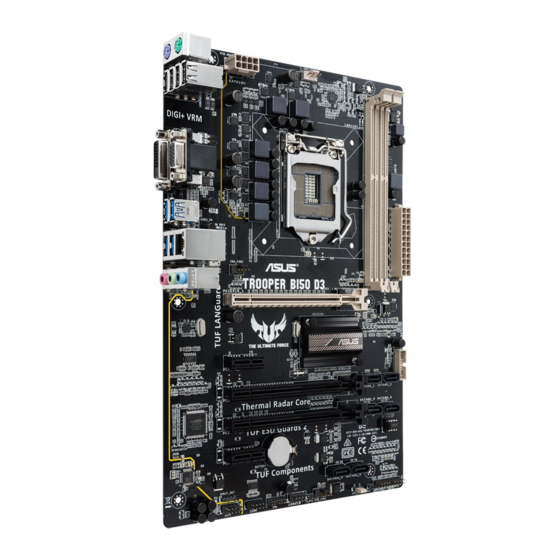
- Page 11 1.2.3 Motherboard layout ASUS TROOPER B150 D3...
- Page 12 1.2.4 Layout contents Connectors/Jumpers/Slots/LED Page ATX power connectors (24-pin EATXPWR, 8-pin EATX12V) 1-24 Intel LGA1151 CPU socket ® CPU and chassis fan connectors (4-pin CPU_FAN, 4-pin CHA_FAN1-2) 1-23 DDR3 DIMM slots USB 3.0 connector (20-1 pin USB3_3_34) 1-27 Intel B150 Serial ATA 6.0Gb/s connector (SATA6G_1~6 [black]) 1-25 ® System panel connector (20-3 pin PANEL) 1-26 Direct Connector (2 pin DRCT) 1-28 CPU Over Voltage jumper (3-pin CPU_OV) 1-19 10. Clear RTC RAM (2-pin CLRTC) 1-18 11. USB 2.0 connector (10-1 pin USB910) 1-23 12. TPM connector (14-1 pin TPM) 1-28 13. Serial port connector (10-1 pin COM) 1-27 14. Front panel audio connector (10-1 pin AAFP) 1-22 15.
-
Page 13: Central Processing Unit (Cpu)
Central Processing Unit (CPU) This motherboard comes with a surface mount LGA1151 socket designed for the 6th Generation Intel Core™ i7 / i5 / i3, Pentium and Celeron processors. ® ® ® Unplug all power cables before installing the CPU. • Upon purchase of the motherboard, ensure that the PnP cap is on the socket and the socket contacts are not bent. Contact your retailer immediately if the PnP cap is missing, or if you see any damage to the PnP cap/socket contacts/motherboard components. ASUS will shoulder the cost of repair only if the damage is shipment/ transit-related. • Keep the cap after installing the motherboard. ASUS will process Return Merchandise Authorization (RMA) requests only if the motherboard comes with the cap on the LGA1151 socket. • The product warranty does not cover damage to the socket contacts resulting from incorrect CPU installation/removal, or misplacement/loss/incorrect removal of the PnP cap. ASUS TROOPER B150 D3... - Page 14 1.3.1 Installing the CPU Chapter 1: Product Introduction...
- Page 15 1.3.2 CPU heatsink and fan assembly installation Apply the Thermal Interface Material to the CPU heatsink and CPU before you install the heatsink and fan if necessary. To install the CPU heatsink and fan assembly ASUS TROOPER B150 D3...
-
Page 16: System Memory
To uninstall the CPU heatsink and fan assembly System memory 1.4.1 Overview This motherboard comes with two Double Data Rate 3 (DDR3) Dual Inline Memory Module (DIMM) sockets. A DDR3 module is notched differently from a DDR or DDR2 module. DO NOT install a DDR or DDR2 memory module to the DDR3 slot. To prevent system instability, either install DDR3L DIMMs or DDR3 DIMMs with voltage lower than 1.5V Channel Sockets Channel A DIMM_A1 Channel B DIMM_B1 Chapter 1: Product Introduction... - Page 17 Recommended memory configurations 1.4.2 Memory configurations You may install 1GB, 2GB, 4GB, 8GB, and 16GB unbuffered non-ECC DDR3 DIMMs into the DIMM sockets. • You may install varying memory sizes in Channel A and Channel B. The system maps the total size of the lower-sized channel for the dual-channel configuration. Any excess memory from the higher-sized channel is then mapped for single-channel operation. • Always install DIMMs with the same CAS latency. For optimal compatibility, we recommend that you install memory modules of the same version or date code (D/C) from the same vendor. Check with the retailer to get the correct memory modules. • Due to the memory address limitation on 32-bit Windows OS, when you install 4GB ® or more memory on the motherboard, the actual usable memory for the OS can be about 3GB or less. For effective use of memory, we recommend that you do any of the following: Use a maximum of 3GB system memory if you are using a 32-bit Windows OS. ® I nstall a 64-bit Windows OS if you want to install 4GB or more on the ® motherboard. • This motherboard does not support DIMMs made up of 512 megabits (Mb) chips or less. ASUS TROOPER B150 D3...
- Page 18 Trooper B150 D3 Motherboard Qualified Vendors Lists (QVL) DDR3 1866 (O.C.) MHz capability Vendors Part No. Size SS/DS Chip Chip NO. Timing Voltage DIMM Brand socket support (Optional) CORSAIR CMD16GX3M2A1866C9 16GB ( 2x 8GB ) 1866 9-9-9-27 • • (Ver5.29)(XMP) CORSAIR CMD16GX3M4A1866C9 16GB ( 4x 4GB ) 9-10-9-27 •...
- Page 19 • (Ver.3.24)(XMP) 8GB ) CORSAIR CMZ16GX3M4X1600C9 16GB ( 4x 1600-9-9- • • (Ver8.16)(XMP) 4GB ) 9-24 CORSAIR CMZ32GX3M4X1600C10 32GB ( 4x 10⁻¹⁰-10-27 • • (Ver2.2)(XMP) 8GB ) CORSAIR CMZ4GX3M1A1600C9 (Ver8.16) 4GB ( 1x 4GB ) 9-9-9-24 • • (XMP) CORSAIR CMZ8GX3M1A1600C10 8GB ( 1x 8GB ) 10-10-10-27 • • (Ver3.23)(XMP) (continued on the next page) ASUS TROOPER B150 D3 1-11...
- Page 20 DDR3 1600 MHz capability Vendors Part No. Size SS/DS Chip Chip NO. Timing Voltage DIMM Brand socket support (Optional) CORSAIR CMZ8GX3M1A1600C10 8GB ( 1x 8GB ) 10-10-10-27 • • (Ver8.21)(XMP) crucial BLS4G3D1609DS1S00.16FMR 1600-9-9- • • (XMP) 9-24 crucial CT102464BA160B.C16FED 8GB crucial CT512X8-160B 11-11-11-28 • •...
- Page 21 • • XTREME Xtreme Silicon SP002GBLTU133V02 2GB S-POWER 20YT3NG 9-9-9-24 • Power Silicon SP004GBLTU133V02 4GB S-POWER 20YT3NG 9-9-9-24 • • Power UMAX 84E44G93UM-13BPSYW UMAX U2S96D30TP-13 1333-9-9-9-24 • • UMAX 84E48G93UM-13BPSYW UMAX U2S96D30TP-13 1333-9-9-9-24 • • ASUS TROOPER B150 D3 1-13...
- Page 22 1.4.3 Installing a DIMM To remove a DIMM Chapter 1: Product Introduction 1-14...
-
Page 23: Expansion Slots
To install an expansion card: Before installing the expansion card, read the documentation that came with it and make the necessary hardware settings for the card. Remove the system unit cover (if your motherboard is already installed in a chassis). Remove the bracket opposite the slot that you intend to use. Keep the screw for later use. Align the card connector with the slot and press firmly until the card is completely seated on the slot. Secure the card to the chassis with the screw you removed earlier. Replace the system cover. 1.5.2 Configuring an expansion card After installing the expansion card, configure it by adjusting the software settings. Turn on the system and change the necessary BIOS settings, if any. See Chapter 2 for information on BIOS setup. Assign an IRQ to the card. Install the software drivers for the expansion card. When using PCI cards on shared slots, ensure that the drivers support “Share IRQ” or that the cards do not need IRQ assignments. Otherwise, conflicts will arise between the two PCI groups, making the system unstable and the card inoperable. ASUS TROOPER B150 D3 1-15... - Page 24 1.5.3 PCI Express 3.0 / 2.0 slots Slot No. Expansion slot PCIe 3.0/2.0 x16_1 slot PCIe 3.0 x1_1 slot PCIe 3.0/2.0 x16_2 slot PCIe 3.0/2.0 x16_3 slot PCIe 3.0 x1_2 slot Chapter 1: Product Introduction 1-16...
- Page 25 PCIe 3.0/2.0 x16_1 PCIe 3.0/2.0 x16_3 x16 (single VGA Single VGA/PCIe card recommended) Dual VGA/PCIe card • We recommend that you provide sufficient power when running CrossFireX™ mode. • Connect a chassis fan to the motherboard connector labeled CHA_FAN1-2 when using multiple graphics cards for better thermal environment. IRQ assignments for this motherboard shared PCIe 3.0/2.0 x16_1 shared PCIe 3.0/2.0 x16_2 shared PCIe 3.0/2.0 x16_3 shared PCIe 3.0 x1_1 shared PCIe 3.0 x1_2 shared Intel PCH SATA Controller shared HD Audio shared USB3.0 shared ASUS TROOPER B150 D3 1-17...
-
Page 26: Jumpers
Jumpers Clear RTC RAM (2-pin CLRTC) This header allows you to clear the Real Time Clock (RTC) RAM in CMOS. You can clear the CMOS memory of date, and system setup parameters by erasing the CMOS RTC RAM data. The onboard button cell battery powers the RAM data in CMOS, which include system setup information such as system passwords. To erase the RTC RAM: Turn OFF the computer and unplug the power cord. Use a metal object such as a screwdriver to short the two pins. Plug the power cord and turn ON the computer. Hold down the <Del> key during the boot process and enter BIOS setup to re- enter data. Except when clearing the RTC RAM, never short-circuit the CLRTC jumper. Shorting the CLRTC jumper will cause system boot failure! • If the steps above do not help, remove the onboard battery and short the two pins again to clear the CMOS RTC RAM data. After clearing the CMOS, reinstall the battery. • You do not need to clear the RTC when the system hangs due to overclocking. For system failure due to overclocking, use the CPU Parameter Recall (C.P.R.) feature. Shut down and reboot the system, then the BIOS automatically resets parameter settings to default values. • Due to chipset behavior, AC power off is required to enable C.P.R. function. You must turn off and on the power supply or unplug and plug the power cord before rebooting the system. - Page 27 CPU Over Voltage jumper (3-pin CPU_OV) The CPU Over Voltage jumper allows you to set a higher CPU voltage for a flexible overclocking system, depending on the type of the installed CPU. To gain more CPU voltage setting, insert the jumper to pins 2-3. To go back to its default CPU voltage setting, insert the jumper to pins 1-2. ASUS TROOPER B150 D3 1-19...
-
Page 28: Connectors
Connectors 1.7.1 Rear panel connectors Rear panel connectors 1. PS/2 mouse port (green) PS/2 keyboard port (purple) 2. USB 2.0 ports 5~8 DVI-D port 3. VGA port LAN_USB3_12 (supports USB 3.0 Boost) 4. USB 3.0 ports 56 (supports USB Audio I/O ports** 3.0 Boost) 5. LAN port* * and **: Refer to the tables on the next page for LAN port LEDs and audio port definitions. Chapter 1: Product Introduction 1-20... - Page 29 **Audio 2.1, 4.1, 5.1 or 7.1-channel configuration Headset Port 4.1-channel 5.1-channel 7.1-channel 2.1-channel Light Blue Line In Rear Speaker Out Rear Speaker Out Rear Speaker Out (Rear panel) Lime (Rear panel) Line Out Front Speaker Out Front Speaker Out Front Speaker Out Pink (Rear panel) Mic In Mic In Bass/Center Bass/Center Lime (Front panel) — — — Side Speaker Out For an 8-channel speaker setup, refer to the 7.1-channel configuration in the table. ASUS TROOPER B150 D3 1-21...
- Page 30 1.7.2 Internal connectors Front panel audio connector (10-1 pin AAFP) This connector is for a chassis-mounted front panel audio I/O module that supports either HD Audio or legacy AC’97 audio standard. Connect one end of the front panel audio I/O module cable to this connector. • We recommend that you connect a high-definition front panel audio module to this connector to avail of the motherboard’s high-definition audio capability. • If you want to connect a high-definition front panel audio module to this connector, set the Front Panel Type item in the BIOS setup to [HD Audio]. If you want to connect an AC’97 front panel audio module to this connector, set the item to [AC97]. By default, this connector is set to [HD Audio]. Digital audio connector (4-1 pin SPDIF_OUT) This connector is for an additional Sony/Philips Digital Interface (S/PDIF) port. Connect the S/PDIF Out module cable to this connector, then install the module to a slot opening at the back of the system chassis. The S/PDIF module is purchased separately. Chapter 1: Product Introduction 1-22...
- Page 31 CPU and chassis fan connectors (4-pin CPU_FAN, 4-pin CHA_FAN1-2) Connect the fan cables to the fan connectors on the motherboard, ensuring that the black wire of each cable matches the ground pin of the connector. DO NOT forget to connect the fan cables to the fan connectors. Insufficient air flow inside the system may damage the motherboard components. These are not jumpers! Do not place jumper caps on the fan connectors! The CPU_FAN connector supports a CPU fan of maximum 1A (12 W) fan power. USB 2.0 connector (10-1 pin USB910) These connectors are for USB 2.0 ports. Connect the USB module cable to any of these connectors, then install the module to a slot opening at the back of the system chassis. These USB connectors comply with USB 2.0 specifications and supports up to 480Mbps connection speed. Never connect a 1394 cable to the USB connectors. Doing so will damage the motherboard! The USB 2.0 module is purchased separately. ASUS TROOPER B150 D3 1-23...
- Page 32 ATX power connectors (24-pin EATXPWR, 8-pin EATX12V) These connectors are for ATX power supply plugs. The power supply plugs are designed to fit these connectors in only one orientation. Find the proper orientation and push down firmly until the connectors completely fit. • For a fully configured system, we recommend that you use a power supply unit (PSU) that complies with ATX 12V specification 2.4 (or later version) and provides a minimum power of 350W • We recommend that you use a PSU with higher power output when configuring a system with more power-consuming devices or when you intend to install additional devices. The system may become unstable or may not boot up if the power is inadequate. • If you want to use two high-end PCI Express x16 cards, use a PSU with 1000W power or above to ensure the system stability. • If you are uncertain about the minimum power supply requirement for your system, refer to the Recommended Power Supply Wattage Calculator at http://support.asus. com/PowerSupplyCalculator/PSCalculator.aspx?SLanguage=en-us for details. Chapter 1: Product Introduction 1-24...
- Page 33 Intel B150 Serial ATA 6.0Gb/s connectors (7-pin SATA6G_1~6 [black]) ® These connectors connect to Serial ATA 6.0 Gb/s hard disk drives via Serial ATA 6.0 Gb/s signal cables. ASUS TROOPER B150 D3 1-25...
- Page 34 System panel connector (20-3 pin PANEL) This connector supports several chassis-mounted functions. • System power LED (3-1 pin or 2-pin PLED) This 3-1 pin or 2-pin connector is for the system power LED. Connect the chassis power LED cable to this connector. The system power LED lights up when you turn on the system power, and blinks when the system is in sleep mode. • Hard disk drive activity LED (2-pin HDD_LED) This 2-pin connector is for the HDD Activity LED. Connect the HDD Activity LED cable to this connector. The HDD LED lights up or flashes when data is read from or written to the HDD. • ATX power button/soft-off button (2-pin PWRSW) This connector is for the system power button. •...
- Page 35 USB 3.0 connector (20-1 pin USB3_34) These connectors allow you to connect a USB 3.0 module for additional USB 3.0 front or rear panel ports. With an installed USB 3.0 module, you can enjoy all the benefits of USB 3.0 including faster data transfer speeds of up to 5Gbps, faster charging time for USB-chargeable devices, optimized power efficiency and backward compatibility with USB 2.0. Serial port connector (10-1 pin COM) This connector is for a serial (COM) port. Connect the serial port module cable to this connector, then install the module to a slot opening at the back of the system chassis. The COM module is purchased separately. ASUS TROOPER B150 D3 1-27...
- Page 36 TPM connector (14-1 pin TPM) This connector supports a Trusted Platform Module (TPM) system, which can securely store keys, digital certificates, passwords, and data. A TPM system also helps enhance network security, protects digital identities, and ensures platform integrity. The TPM module is purchased separately. Direct Connector (2 pin DRCT) This connector is for the chassis-mounted button that supports the DirectKey function. Connect the button cable that supports DirectKey, from the chassis to this connector on the motherboard. Ensure that your chassis comes with the button cable that supports the DirectKey feature. Refer to technical documentation that came with the chassis for details. Chapter 1: Product Introduction 1-28...
-
Page 37: Onboard Leds
Onboard LEDs Standby Power LED (SB_PWR) The motherboard comes with a standby power LED that lights up to indicate that the system is ON, in sleep mode, or in soft-off mode. This is a reminder that you should shut down the system and unplug the power cable before removing or plugging in any motherboard component. The illustration below shows the location of the onboard LED. ASUS TROOPER B150 D3 1-29... - Page 38 Chapter 1: Product Introduction 1-30...
-
Page 39: Chapter 2: Bios Information
Managing and updating your BIOS Save a copy of the original motherboard BIOS file to a USB flash disk in case you need to restore the BIOS in the future. Copy the original motherboard BIOS using the ASUS Update utility. - Page 40 2.1.2 ASUS EZ Flash 3 ASUS EZ Flash 3 allows you to download and update to the latest BIOS through the Internet without having to use a bootable floppy disk or an OS‑based utility. Updating through the Internet varies per region and Internet conditions. Check your local Internet connection before updating through the Internet.
- Page 41 To update the BIOS by Internet: Enter the Advanced Mode of the BIOS setup program. Go to the Tool menu to select ASUS EZ Flash Utility and press <Enter>. Select by Internet. Press the Left/Right arrow keys to select an Internet connection method, and then press <Enter>.
- Page 42 2.1.3 ASUS CrashFree BIOS 3 utility The ASUS CrashFree BIOS 3 is an auto recovery tool that allows you to restore the BIOS file when it fails or gets corrupted during the updating process. You can restore a corrupted BIOS file using the motherboard support DVD or a USB flash drive that contains the updated BIOS file.
- Page 43 To update the BIOS file: On the FreeDOS prompt, type bupdater /pc /g and press <Enter>. D:/> bupdater /pc /g On the BIOS Updater screen, press <Tab> to switch from Files panel to Drives panel then select D:. ASUS TROOPER B150 D3...
- Page 44 ASUSTeK BIOS Updater for DOS V1.30 [2015/01/01] Current ROM Update ROM BOARD: TROOPER B150 D3 BOARD: Unknown VER: 0310 (H :00 B :00) VER: Unknown DATE: 02/02/2015 DATE: Unknown PATH: FORMAN~1 <DIR> B150TP.CAP 8390656 2015-02-02 21:14:34 Drives panel Files panel...
-
Page 45: Bios Setup Program
The BIOS setup screens shown in this section are for reference purposes only, and may not exactly match what you see on your screen. • Visit the ASUS website at www.asus.com to download the latest BIOS file for this motherboard. •... - Page 46 BIOS menu screen The BIOS setup program can be used under two modes: EZ Mode and Advanced Mode. You can change modes from the Exit menu or from the Exit/Advanced Mode button in the EZ Mode/Advanced Mode screen. EZ Mode By default, the EZ Mode screen appears when you enter the BIOS setup program.
- Page 47 The Advanced Mode provides advanced options for experienced end‑users to configure the BIOS settings. The figure below shows an example of the Advanced Mode. To access the EZ Mode, click Exit, then select ASUS EZ Mode or press <F7>. MyFavorite(F3)
-
Page 48: My Favorites
My Favorites My Favorites is your personal space where you can easily save and access your favorite BIOS items. My Favorites comes with several performance, power saving, and fast boot related items by default. You can personalize this screen by adding or removing items. Adding items to My Favorites To add frequently‑used BIOS items to My Favorites: Press <F3>... -
Page 49: Main Menu
RAM to clear the BIOS password. See section 1.6 Jumpers for information on how to erase the RTC RAM. • The Administrator or User Password items on top of the screen show the default Not Installed. After you set a password, these items show Installed. ASUS TROOPER B150 D3 2-11... -
Page 50: Ai Tweaker Menu
Ai Tweaker menu The Ai Tweaker menu items allow you to configure overclocking‑related items. Be cautious when changing the settings of the Ai Tweaker menu items. Incorrect field values can cause the system to malfunction. The configuration options for this section vary depending on the CPU and DIMM model you installed on the motherboard. -
Page 51: Advanced Menu
Be cautious when changing the settings of the Advanced menu items. Incorrect field values can cause the system to malfunction. Monitor menu The Monitor menu displays the system temperature/power status, and allows you to change the fan settings. Scroll down on the menu to display more items. ASUS TROOPER B150 D3 2‑13... -
Page 52: Boot Menu
Boot menu The Boot menu items allow you to change the system boot options. Scroll down on the menu to display more items. Tool menu The Tools menu items allow you to configure options for special functions. Select an item then press <Enter>... -
Page 53: Exit Menu
The Exit menu items allow you to load the optimal default values for the BIOS items, and save or discard your changes to the BIOS items. You can access the EZ Mode from the Exit menu. ASUS TROOPER B150 D3 2-15... - Page 54 2-16 Chapter 2: BIOS Information...
-
Page 55: Chapter 3: Software Support
Click to display product related information. Click to select an item to install Click to display the ASUS contact information Click to browse the file list of the suport CD Click to install the selected items ASUS TROOPER B150 D3... -
Page 56: Obtaining The Software Manuals
Acrobat Reader from the Utilities tab before opening the files. ® To read about your motherboard’s utility guide: Click Manual tab > ASUS Motherboard Installation Guide. From the Manual folder, open the folder of the software manual that you wish to read. -
Page 57: Ai Suite 3
Launching AI Suite 3 Windows 7 OS ® From the Desktop, click Start > All Programs > ASUS > AI Suite 3 > AI Suite 3. You can also launch AI Suite 3 in Windows 7 by clicking on the Notification area. -
Page 58: Thermal Radar Core
Thermal Radar Core ASUS Thermal Radar Core offers you an efficient thermal management system to monitor CPU temperature and voltages, control overclocking settings, and adjust fan speeds and voltages manually or automatically. ASUS Thermal Core includes these three main management screens: Fan Control, Recorder, and DIGI+ VRM. - Page 59 The RPM mode allows you to set the fan speed when the temperature is below 75ºC. Drag the slider up or down to adjust the fan speed Click or tap to go back to main screen Click or tap to switch between CPU and chassis fan screens ASUS TROOPER B150 D3...
- Page 60 CPU Assessment The CPU Assessment utility allows you to get an assessment of the CPU’s temperature during system load. Click or tap to get CPU Assessment Live Update The Live Update utility allows you to get the latest firmware updates. Click or tap to get live updates Chapter 3: Software Support...
-
Page 61: Recorder Screen
It also provides the highest power efficiency, generating less heat to extend component lifespan and minimize power loss. Help contents Click or tap to undo Click or tap to the changes apply the changes ASUS TROOPER B150 D3... - Page 62 CPU Load-line Calibration CPU Load-line Calibration adjusts the voltage range and controls the system temperature. Higher load-line calibration could get higher voltage and good overclocking performance but increases the CPU and VRM thermal conditions. CPU Current Capability CPU Current Capability provides wider total power range for overclocking. A higher value setting gets higher VRM power consumption delivery.
-
Page 63: Appendices
Consult the dealer or an experienced radio/TV technician for help. The use of shielded cables for connection of the monitor to the graphics card is required to assure compliance with FCC regulations. Changes or modifications to this unit not expressly approved by the party responsible for compliance could void the user’s authority to operate this equipment. ASUS TROOPER B150 D3... - Page 64 IC: Canadian Compliance Statement Complies with the Canadian ICES-003 Class B specifications. This device complies with RSS 210 of Industry Canada. This Class B device meets all the requirements of the Canadian interference-causing equipment regulations. This device complies with Industry Canada license exempt RSS standard(s). Operation is subject to the following two conditions: (1) this device may not cause interference, and (2) this device must accept any interference, including interference that may cause undesired operation of the device.
- Page 65 ASUS Recycling/Takeback Services ASUS recycling and takeback programs come from our commitment to the highest standards for protecting our environment. We believe in providing solutions for you to be able to responsibly recycle our products, batteries, other components as well as the packaging materials.
- Page 66 Slovenščina AsusTek Inc. tukaj izjavlja, da je ta naprava skladna s temeljnimi di conformità CE. zahtevami in drugimi relevantnimi določili direktiv CE. Za več informacij Компания ASUS заявляет, что это устройство соответствует основным glejte Izjavo CE o skladnosti. требованиям и другим соответствующим условиям европейских...
- Page 67 +1-510-739-3777 +1-510-608-4555 Web site http://www.asus.com/us/ Technical Support Support fax +1-812-284-0883 Telephone +1-812-282-2787 Online support http://www.service.asus.com/ ASUS COMPUTER GmbH (Germany and Austria) Address Harkort Str. 21-23, D-40880 Ratingen, Germany +49-2102-959911 Web site http://www.asus.com/de Online contact http://eu-rma.asus.com/sales Technical Support Telephone +49-1805-010923 Support Fax...
- Page 68 Appendix...