Table of Contents
Advertisement
Quick Links
Advertisement
Table of Contents

Related Manuals for Asus B150M-C D3


Summary of Contents for Asus B150M-C D3
- Page 1 B150M-C D3 B150M-C D3/CSM...
- Page 2 INCIDENTAL, OR CONSEQUENTIAL DAMAGES (INCLUDING DAMAGES FOR LOSS OF PROFITS, LOSS OF BUSINESS, LOSS OF USE OR DATA, INTERRUPTION OF BUSINESS AND THE LIKE), EVEN IF ASUS HAS BEEN ADVISED OF THE POSSIBILITY OF SUCH DAMAGES ARISING FROM ANY DEFECT OR ERROR IN THIS MANUAL OR PRODUCT.
-
Page 3: Table Of Contents
Contents Safety information ..................iv About this guide ..................iv Package contents ..................vi B150M-C D3 specifications summary ............vi Chapter 1 Product introduction Before you proceed ..............1-1 Motherboard overview ..............1-1 Central Processing Unit (CPU) ........... 1-3 System memory ................1-7 Expansion slots ................ -
Page 4: Safety Information
Safety information Electrical safety before relocating the system. When adding or removing devices to or from the system, ensure that the power cables for the devices are unplugged before the signal cables are connected. If possible, disconnect all power cables from the existing system before you add a device. Before connecting or removing signal cables from the motherboard, ensure that all power cables are unplugged. - Page 5 Refer to the following sources for additional information and for product and software updates. ASUS websites The ASUS website provides updated information on ASUS hardware and software products. Refer to the ASUS contact information. Optional documentation that may have been added by your dealer. These documents are not part of the standard package.
-
Page 6: Package Contents
CPUs. Please refer to Memory QVL for details. ** To prevent system instability, either install DDR3L DIMMs or DDR3 DIMMs with voltage lower than 1.5V. *** Refer to www.asus.com for the latest Memory QVL (Qualified Vendors List). Graphics Integrated graphics processor... - Page 7 - ASUS Overvoltage Protection - World-class circuit-protecting power design - ASUS DRAM Overcurrent Protection - Prevents damage from short circuits - ASUS Stainless Steel Back I/O - 3X corrosion-resistance for greater durability - ESD Guards - Electrostatic discharge protection - Most advanced options with fast response time...
- Page 8 1 x 4-pin ATX 12V power connector BIOS features 128 Mb Flash ROM, UEFI AMI BIOS, PnP, DMI3.0, WfM2.0, SM BIOS 3.0, ACPI 5.0, Multi-language BIOS, ASUS EZ Flash 3, CrashFree BIOS 3, F3 My SPD (Serial Presence Detect) memory information, F6 Qfan Control Manageability WfM 2.0, DMI 3.0, WOL by PME, PXE...
-
Page 9: Chapter 1 Product Introduction
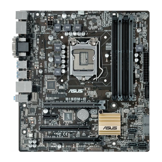
Placement direction with external ports goes to the rear part of the chassis as indicated in the image. 1.2.2 Screw holes Place six screws into the holes indicated by circles to secure the motherboard to the chassis. ASUS B150M-C D3... - Page 10 Place this side towards the rear of the chassis B150M-C D3 1.2.3 Motherboard layout 22.6cm(8.9in) KBMS CPU_FAN HDMI_DP EATX12V 1442K 1442 LGA1151 USB3_34 USB3_56 Super CHA_FAN1 LAN_USB56 COM2 AUDIO B150M-C D3 USB3_12 PCIEX16_1 Realtek 8111F SATA6G_4 PCIEX1_1 1083 Intel ®...
-
Page 11: Central Processing Unit (Cpu)
1.2.4 Layout contents Connectors/Jumpers/Slots/LED Page ® 1-19 ® 1-18 1-12 1-11 1-19 1-18 Central Processing Unit (CPU) ® ® ® processors. B150M-C D3 B150M-C D3 CPU socket LGA1151 ASUS B150M-C D3... - Page 12 components. cap. 1.3.1 Installing the CPU Chapter 1: Product introduction...
- Page 13 1.3.2 CPU heatsink and fan assembly installation before you install the heatsink and fan if necessary. ASUS B150M-C D3...
- Page 14 To install the CPU heatsink and fan assembly To uninstall the CPU heatsink and fan assembly Chapter 1: Product introduction...
-
Page 15: System Memory
System memory 1.4.1 Overview Channel Sockets B150M-C D3 B150M-C D3 240-pin DDR3 DIMM sockets 1.4.2 Memory configurations Recommended memory configurations ASUS B150M-C D3... - Page 16 operation. ® ® ® ® motherboard. ® support site at 2.5 Ai Tweaker menu for manual memory modules. Chapter 1: Product introduction...
- Page 17 1.4.3 Installing a DIMM 1.4.4 Removing a DIMM ASUS B150M-C D3...
-
Page 18: Expansion Slots
Expansion slots the slots and the expansion cards that they support. cause you physical injury and damage motherboard components. 1.5.1 Installing an expansion card To install an expansion card: make the necessary hardware settings for the card. use. seated on the slot. 1.5.2 Configuring an expansion card 1.5.3... -
Page 19: Headers
– – – shared – – – shared – – – Headers Clear RTC RAM (2-pin CLRTC) CLRTC B150M-C D3 PIN 1 B150M-C D3 Clear RTC RAM To erase the RTC RAM: enter data. battery. ASUS B150M-C D3 1-11... - Page 20 Chassis intrusion header (4-1 pin CHASSIS) one end of the chassis intrusion sensor or switch cable to this connector. The chassis detection feature. CHASSIS B150M-C D3 Chassis intrusion connector 1-12 Chapter 1: Product introduction...
-
Page 21: Connectors
Speed LED Speed Activity Link Status Description Status Description Linked 1Gbps connection LAN port wake up from Line In port (light blue). audio sources. Line Out port (lime). Microphone port (pink). This port connects to a microphone. ASUS B150M-C D3 1-13... - Page 22 Audio 2.1, 4.1, 5.1, or 7.1-channel configuration Headset Port 4.1-channel 5.1-channel 7.1-channel 2.1-channel To configure an 7.1-channel audio output: output. USB 2.0 ports. USB 3.0 ports ® DVI-D port. ® ® display architecture design supports the following maximum supported pixel HDMI port.
- Page 23 1.7.2 Internal connectors LPT connector (26-1 pin LPT) computers. PIN 1 B150M-C D3 B150M-C D3 Parallel Port Connector ATX power connectors (24-pin EATXPWR, 4-pin ATX12V) ATX12V EATXPWR PIN 1 +3 Volts +12V DC +12 Volts +5 Volts +12V DC +12 Volts...
- Page 24 Front panel audio connector (10-1 pin AAFP) AAFP PIN 1 B150M-C D3 HD-audio-compliant pin definition B150M-C D3 Front panel audio connector TPM connector (14-1 pin TPM) PIN 1 B150M-C D3 B150M-C D3 TPM connector Chapter 1: Product introduction...
- Page 25 CHA FAN PWR CHA FAN IN CHA FAN PWM CHA_FAN1 B150M-C D3 B150M-C D3 Fan connectors Speaker connector (4-pin SPEAKER) allows you hear system beeps and warnings. SPEAKER B150M-C D3 PIN 1 B150M-C D3 Speaker Out connector ASUS B150M-C D3...
- Page 26 Serial port connector (10-1 pin COM) COM2 COM1 PIN 1 PIN 1 B150M-C D3 B150M-C D3 Serial port (COM) connectors Intel ® B150 Serial ATA 6.0Gb/s connector (7-pin SATA6G_1~6 [gray]) signal cables. SATA6G_4 SATA6G_5 SATA6G_1 RSATA_TXP1 RSATA_TXN1 RSATA_RXP1 RSATA_RXN1 SATA6G_3...
- Page 27 IntA_P2_SSRX+ IntA_P1_SSTX- B150M-C D3 IntA_P2_SSTX- IntA_P1_SSTX+ IntA_P2_SSTX+ IntA_P1_D- IntA_P2_D- IntA_P1_D+ IntA_P2_D+ B150M-C D3 USB3.0 Front panel connector USB 2.0 connectors (10-1 pin USB78, USB910) USB78 USB910 B150M-C D3 PIN 1 PIN 1 B150M-C D3 USB2.0 connectors ASUS B150M-C D3 1-19...
- Page 28 PIN 1 B150M-C D3 +HDD_LED RESET B150M-C D3 System panel connector This connector is for the system power button. This 2-pin connector is for the chassis-mounted reset button for system reboot without turning off the system power. Chapter 1: Product introduction...
-
Page 29: Software Support
1.8.2 Support DVD information To run the Support DVD menus. The following screen is for reference only. Click to install Click an icon Tick an item and click Install to display to install it a tab ASUS B150M-C D3 1-21... - Page 30 1.8.3 Intel ® SBA support ® ® Platform requirements: ® ® ® ® ® CPU and chipsets requirements: ® ® ® ® ® www.asus.com 1-22 Chapter 1: Product introduction...
- Page 31 ® operating system documentation for detailed information. Windows ® 7 and USB 3.0 driver for 100 Series ® ® Method 1: Using SATA ODD & USB devices ® Requirement: ® ® mode. ® ® boot screen. ASUS B150M-C D3 1-23...
- Page 32 ® Chapter 1: Product introduction...
- Page 33 Method 2: Using a modified Windows ® 7 ISO ® ® Requirement: ® ® ® ® platform. boot screen. ® ASUS B150M-C D3...
- Page 34 Method 3: Using ASUS EZ Installer ® Requirement: ® ® ® ® Windows 7 OS disk to USB storage device then click Next. I agree and then click Next. Chapter 1: Product introduction...
- Page 35 Next. ® next. ASUS B150M-C D3...
- Page 36 ® ® Windows 7 OS disk to ISO file then click Next. I agree and then click Next. Next. ® 1-28 Chapter 1: Product introduction...
- Page 37 ® Next. ® ® ® platform. boot screen. ® ASUS B150M-C D3 1-29...
- Page 38 Chapter 1: Product introduction...
-
Page 39: Bios Information
Managing and updating your BIOS 2.1.1 EZ Update EZ Update Click to automatically update your motherboard’s driver, software and firmware Click to find and Click to select a Click to update select the BIOS boot logo the BIOS from file ASUS B150M-C D3... - Page 40 2.1.2 ASUS EZ Flash 3 2.10 Exit Menu To update the BIOS using EZ Flash 3: Advanced Mode Tool Via USB by USB Drive Folder Info Via the Internet by Internet Chapter 2: Getting started...
- Page 41 2.1.3 ASUS CrashFree BIOS 3 utility B150C.CAP Recovering the BIOS To recover the BIOS: 2.1.4 ASUS BIOS Updater Before updating BIOS ASUS B150M-C D3...
- Page 42 Booting the system in DOS environment Please select boot device: ASUS DVD-E818A6T (4069MB) USB DISK 2.0 (3824MB) UEFI: (FAT) USB DISK 2.0 (3824MB) Enter Setup to move selection ENTER to select boot device ESC to boot using defaults ISOLINUX 3.20 2006-08-26 Copyright (C) 1994-2005 H. Peter Anvin A Bootable DVD/CD is detected.
- Page 43 <DIR> B150C.CAP 8390656 2015-07-31 21:14:34 Drives panel Files panel Note [Enter] Select or Load [Tab] Switch [V] Drive Info [Up/Down/Home/End] Move [Esc] Exit Are you sure you want to update the BIOS? the Load Optimized Defaults Exit ASUS B150M-C D3...
-
Page 44: Bios Setup Program
BIOS setup program Entering BIOS Setup at startup To enter BIOS Setup at startup: Entering BIOS Setup after POST To enter BIOS Setup after POST: www.asus.com Load Optimized Defaults 2.10 Exit Menu 1.6 Headers for information BIOS menu screen EZ Mode and Advanced Mode... - Page 45 Shows the Displays the CPU Fan’s speed. Click bootable and resets the the button to manually tune the fans devices system Selects the boot Loads optimized default device priority settings Displays the Advanced mode menus Boot Menu(F8) ASUS B150M-C D3...
- Page 46 Advanced Mode Advanced Mode EzMode(F7) Quick Note Hot Keys MyFavorite Q-Fan Language Menu bar control Last modified Sub-menu item General help Popup Window Scroll bar settings Menu items Goes back to EZ Mode Displays the CPU/motherboard Configuration fields temperature, CPU and memory voltage output Menu bar Main...
- Page 47 Click to select a fan to be Click to activate DC Mode PWM Mode configured Click to apply the Click to go Click to undo the Select a profile to apply to fan setting back to main changes your fans menu ASUS B150M-C D3...
- Page 48 Configuring fans manually Select Manual Click to manually configure your fans Speed points Apply Exit (ESC) 2-10 Chapter 2: Getting started...
-
Page 49: My Favorites
My Favorites Adding items to My Favorites Main menu panel Selected shortcut items Submenu panel Exit (ESC) ASUS B150M-C D3 2-11... -
Page 50: Main Menu
Main menu 2-12 Chapter 2: Getting started... -
Page 51: Ai Tweaker Menu
Ai Tweaker menu ASUS B150M-C D3... -
Page 52: Advanced Menu
Advanced menu Monitor menu 2-14 Chapter 2: Getting started... -
Page 53: Boot Menu
Boot menu Tool menu ASUS B150M-C D3... -
Page 54: Exit Menu
2.10 Exit menu Chapter 2: Getting started... -
Page 55: Appendices
Consult the dealer or an experienced radio/TV technician for help. The use of shielded cables for connection of the monitor to the graphics card is required expressly approved by the party responsible for compliance could void the user’s authority to operate this equipment. B150M-C D3... - Page 56 IC: Canadian Compliance Statement 210 of Industry Canada. This Class B device meets all the requirements of the Canadian interference-causing equipment regulations. This device complies with Industry Canada license exempt RSS standard(s). Operation is subject to the following two conditions: (1) this device may not cause interference, and (2) this device must accept any interference, including interference that may cause undesired operation of the device.
- Page 57 ASUS Recycling/Takeback Services ASUS recycling and takeback programs come from our commitment to the highest standards for protecting our environment. We believe in providing solutions for you to be able to responsibly recycle our products, batteries, other components as well as the packaging materials.
- Page 58 Português A AsusTek Inc. declara que este dispositivo está em English AsusTek Inc. hereby declares that this device is in compliance with conformidade com os requisitos essenciais e outras disposições relevantes the essential requirements and other relevant provisions of CE Directives. das Diretivas da CE.
-
Page 59: Asus Contact Information
+1-510-739-3777 +1-510-608-4555 Web site http://www.asus.com/us/ Technical Support Support fax +1-812-284-0883 General support +1-812-282-2787 Online support http://www.service.asus.com/ ASUS COMPUTER GmbH (Germany and Austria) Address Harkort Str. 21-23, D-40880 Ratingen, Germany +49-2102-959931 Web site http://www.asus.com/de Online contact http://eu-rma.asus.com/sales Technical Support Telephone +49-2102-5789555... - Page 60 Appendices...