Table of Contents
Advertisement
Quick Links
GE Consumer & Industrial
Multilin
GE Multilin
215 Anderson Avenue, Markham, Ontario, Canada L6E 1B3
Tel: (905) 294-6222, 1-800-547-8629 (North America)
Fax: (905) 201-2098
Internet:
http://www.GEmultilin.com
*1601-9047-A1*
369 Motor Management Relay
QuickStart Guide
369 Revision: 3.2x
Manual P/N: 1601-9047-A1 (GEK-113494)
Copyright © 2008 GE Multilin
GE Multilin's Quality Management
System is registered to
ISO9001:2000
QMI # 005094
UL # A3775
Advertisement
Table of Contents

Related Manuals for GE Multilin 369


Summary of Contents for GE Multilin 369
- Page 1 Multilin 369 Motor Management Relay QuickStart Guide 369 Revision: 3.2x Manual P/N: 1601-9047-A1 (GEK-113494) Copyright © 2008 GE Multilin GE Multilin 215 Anderson Avenue, Markham, Ontario, Canada L6E 1B3 Tel: (905) 294-6222, 1-800-547-8629 (North America) Fax: (905) 201-2098 GE Multilin's Quality Management Internet: http://www.GEmultilin.com...
- Page 2 The contents of this manual are the property of GE Multilin Inc. This documentation is furnished on license and may not be reproduced in whole or in part without the permission of GE Multilin. The content of this manual is for informational use only and is subject to change without notice.
-
Page 3: Table Of Contents
TABLE OF CONTENTS Table of Contents 1: INTRODUCTION ORDERING ..........................1-1 ......................1-1 ENERAL VERVIEW 369 F .................... 1-2 UNCTIONAL UMMARY ....................1-3 ELAY ABEL EFINITION 2: INSTALLATION MECHANICAL INSTALLATION ..................2-5 ....................2-5 ECHANICAL NSTALLATION TERMINAL IDENTIFICATION ...................2-7 369 T ......................2-7 ERMINAL ...................... - Page 4 TABLE OF CONTENTS ....................4-40 XAMPLE HORT IRCUIT S8 POWER ELEMENTS ......................4-42 ........................4-42 ESCRIPTION ......................4-43 OWER ACTOR ......................4-43 OWER ACTOR ....................4-44 OSITIVE EACTIVE OWER ..................... 4-45 EGATIVE EACTIVE OWER ........................4-46 NDERPOWER ......................... 4-47 EVERSE OWER S9 DIGITAL INPUTS ......................4-48 ....................
-
Page 5: General Overview
369 options are available when ordering the relay or as upgrades to the relay in the field. Field upgrades are via an option enabling passcode available from GE Multilin, which is unique to each relay and option. 369 MOTOR MANAGEMENT RELAY – QUICKSTART GUIDE... -
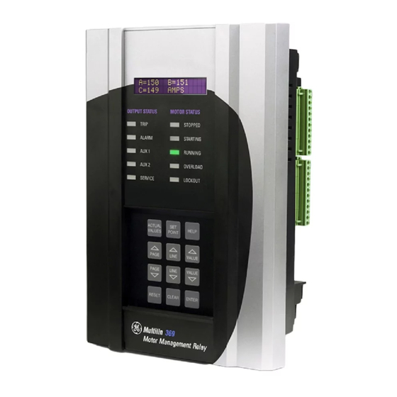
Page 6: Unctional Ummary
ORDERING CHAPTER 1: INTRODUCTION 1.1.2 369 Functional Summary The front view for all 369 Relay models is shown below, along with the rear view showing the Profibus port, the Modbus/TCP port, and the DeviceNet port. DISPLAY 40 Character alpha-numeric LCD display for viewing actual values, causes of alarms and trips, and programming setpoints... -
Page 7: Relay Label Definition
CHAPTER 1: INTRODUCTION ORDERING 1.1.3 Relay Label Definition MAXIMUM CONTACT RATING 250 VAC RESISTIVE 1/4 HP 125 VAC 1/2 HP 250 VAC OPTIONS MODEL: 369-HI-R-B-F-P-0 SERIAL No: M53C07000001 12 RTDs: FIRMWARE: 53CMC320.000 BACKSPIN INPUT POWER: FIBER OPTIC PORT 50-300 VDC PROFIBUS 60-265 VAC 485mA MAX. - Page 8 ORDERING CHAPTER 1: INTRODUCTION 1–4 369 MOTOR MANAGEMENT RELAY – QUICKSTART GUIDE...
-
Page 9: Mechanical Installation
GE Consumer & Industrial Multilin 369 Motor Management Relay Chapter 2: Installation Installation Mechanical Installation 2.1.1 Mechanical Installation The 369 is contained in a compact plastic housing with the keypad, display, communication port, and indicators/targets on the front panel. The unit should be positioned so the display and keypad are accessible. - Page 10 MECHANICAL INSTALLATION CHAPTER 2: INSTALLATION FIGURE 2–2: Split Mounting Dimensions 2–6 369 MOTOR MANAGEMENT RELAY – QUICKSTART GUIDE...
-
Page 11: Terminal Identification
CHAPTER 2: INSTALLATION TERMINAL IDENTIFICATION Terminal Identification 2.2.1 369 Terminal List TERMINAL WIRING CONNECTION RTD1 + RTD1 – RTD1 COMPENSATION RTD1 SHIELD RTD2 + RTD2 – RTD2 COMPENSATION RTD2 SHIELD RTD3 + RTD3 – RTD3 COMPENSATION RTD3 SHIELD RTD4 + RTD4 –... - Page 12 TERMINAL IDENTIFICATION CHAPTER 2: INSTALLATION TERMINAL WIRING CONNECTION RTD11 SHIELD RTD12 + RTD12 – RTD12 COMPENSATION RTD12 SHIELD SPARE SW SPARE SW COMMON DIFFERENTIAL INPUT SW DIFFERENTIAL INPUT SW COMMON SPEED SW SPEED SW COMMON ACCESS SW ACCESS SW COMMON EMERGENCY RESTART SW EMERGENCY RESTART SW COMMON EXTERNAL RESET SW...
-
Page 13: Terminal Layout
CHAPTER 2: INSTALLATION TERMINAL IDENTIFICATION TERMINAL WIRING CONNECTION PHASE B VOLTAGE PHASE B NEUTRAL PHASE C VOLTAGE PHASE C NEUTRAL TRIP NC TRIP COMMON TRIP NO ALARM NC ALARM COMMON ALARM NO AUX1 NC AUX1 COMMON AUX1 NO AUX2 NC AUX2 COMMON AUX2 NO POWER FILTER GROUND... -
Page 14: Electrical Installation
ELECTRICAL INSTALLATION CHAPTER 2: INSTALLATION Electrical Installation 2.3.1 Typical Wiring Diagram FIGURE 2–4: Typical Wiring 2–10 369 MOTOR MANAGEMENT RELAY – QUICKSTART GUIDE... -
Page 15: Typical Wiring
A recommended and tested cable is available from GE Multilin. The cable should be wired as far away as possible from high current or voltage carrying cables or other sources of electrical noise. -
Page 16: Output Relays
ELECTRICAL INSTALLATION CHAPTER 2: INSTALLATION In addition the display module must be grounded if mounted remotely. A ground screw is provided on the back of the display module to facilitate this. A 12 AWG wire is recommended and should be connected to the same ground bus as the main relay unit. The 369 relay will still function and protect the motor without the display connected. - Page 17 CHAPTER 2: INSTALLATION ELECTRICAL INSTALLATION Up to 32 369s (or other devices) can be daisy-chained together on a single serial communication channel without exceeding the driver capability. For larger systems, additional serial channels must be added. Commercially available repeaters may also be used to increase the number of relays on a single channel to a maximum of 254.
- Page 18 ELECTRICAL INSTALLATION CHAPTER 2: INSTALLATION 2–14 369 MOTOR MANAGEMENT RELAY – QUICKSTART GUIDE...
-
Page 19: Display
GE Consumer & Industrial Multilin 369 Motor Management Relay Chapter 3: User Interfaces User Interfaces Faceplate Interface 3.1.1 Display All messages are displayed on a 40-character LCD display to make them visible under poor lighting conditions and from various viewing angles. Messages are displayed in plain English and do not require the aid of an instruction manual for deciphering. -
Page 20: Rs232 Program Port
FACEPLATE INTERFACE CHAPTER 3: USER INTERFACES FIGURE 3–1: LED Indicators - Enhanced Faceplate FIGURE 3–2: LED Indicators - Basic Faceplate 3.1.3 RS232 Program Port This port is intended for connection to a portable PC. Setpoint files may be created at any location and downloaded through this port using the EnerVista 369 Setup software. -
Page 21: Setpoint Entry
CHAPTER 3: USER INTERFACES FACEPLATE INTERFACE • [PAGE]: The Page Up/ Page Down keys may be used to scroll through page headers for both Setpoints and Actual Values. • [LINE]: Once the required page is found, the Line Up/ Line Down keys may be used to scroll through the sub-headings. -
Page 22: Enervista 369 Setup Interface
If EnerVista 369 Setup is currently installed, note the path and directory name. It may be required during upgrading. The EnerVista 369 Setup software is included on the GE enerVista CD that accompanied the 369. The software may also be downloaded from the GE Multilin website at http:// www.GEindustrial.com/multilin. - Page 23 CHAPTER 3: USER INTERFACES ENERVISTA 369 SETUP INTERFACE EnerVista Launchpad will obtain the installation program from the Web or CD. Once the download is complete, double-click the installation program to install the EnerVista 369 Setup software. The program will request the user to create a backup 3.5" floppy-disk set. If this is desired, click on the Start Copying button;...
- Page 24 ENERVISTA 369 SETUP INTERFACE CHAPTER 3: USER INTERFACES Click Finish to end the installation. The 369 device will be added to the list of installed IEDs in the enerVista Launchpad window, as shown below. 3–20 369 MOTOR MANAGEMENT RELAY – QUICKSTART GUIDE...
-
Page 25: Connecting Enervista 369 Setup To The Relay
(for RS232 communications) or to the RS485 terminals on the back of the device (for RS485 communications). This example demonstrates an RS232 connection. For RS485 communications, the GE Multilin F485 converter will be required. Refer to the F485 manual for additional details. To configure the relay for Ethernet communications, see Configuring Ethernet Communications on page 3–23. - Page 26 CONNECTING ENERVISTA 369 SETUP TO THE RELAY CHAPTER 3: USER INTERFACES Enter the slave address and COM port values (from the S1 369 SETUP menu) in the Slave Address and COM 369 COMMUNICATIONS Port fields. Enter the physical communications parameters (baud rate and parity settings) in their respective fields.
-
Page 27: Using The Quick Connect Feature
CHAPTER 3: USER INTERFACES CONNECTING ENERVISTA 369 SETUP TO THE RELAY 3.3.2 Using the Quick Connect Feature The Quick Connect button can be used to establish a fast connection through the front panel RS232 port of a 369 relay. The following window will appear when the Quick Connect button is pressed: As indicated by the window, the Quick Connect feature quickly connects the EnerVista 369 Setup software to a 369 front port with the following settings: 9600 baud, no parity, 8 bits,... - Page 28 CHAPTER 3: USER INTERFACES Install and start the latest version of the EnerVista 369 Setup software (available from the GE enerVista CD). See the previous section for the installation procedure. Click on the Device Setup button to open the Device Setup window.
-
Page 29: Connecting To The Relay
CHAPTER 3: USER INTERFACES CONNECTING ENERVISTA 369 SETUP TO THE RELAY Click the Read Order Code button to connect to the 369 device and upload the order code. If an communications error occurs, ensure that the 369 Ethernet communications values entered in the previous step correspond to the relay and MultiNET setting values. - Page 30 CONNECTING ENERVISTA 369 SETUP TO THE RELAY CHAPTER 3: USER INTERFACES Expand the Settings > Relay Setup list item and double click on Front Panel to open the Front Panel settings window as shown below: FIGURE 3–3: Main Window After Connection The Front Panel settings window will open with a corresponding status indicator on the lower left of the EnerVista 369 Setup window.
-
Page 31: Keypad Setpoints Main Menu
GE Consumer & Industrial Multilin 369 Motor Management Relay Chapter 4: Keypad Setpoints Keypad Setpoints Overview 4.1.1 Keypad Setpoints Main Menu S1 SETPOINTS SETPOINT ACCESS 369 SETUP DISPLAY PREFERENCES 369 COMMUNICATIONS REAL TIME CLOCK WAVEFORM CAPTURE DATA LOGGER EVENT RECORDS... - Page 32 OVERVIEW CHAPTER 4: KEYPAD SETPOINTS FACTORY SERVICE S2 SETPOINTS CT/VT SETUP SYSTEM SETUP MONITORING SETUP BLOCK FUNCTIONS OUTPUT RELAY SETUP CONTROL FUNCTIONS S3 SETPOINTS THERMAL MODEL OVERLOAD PROTECTION OVERLOAD CURVES OVERLOAD ALARM S4 SETPOINTS SHORT CIRCUIT CURRENT ELEMENTS MECHANICAL JAM UNDERCURRENT CURRENT UNBALANCE GROUND FAULT...
- Page 33 CHAPTER 4: KEYPAD SETPOINTS OVERVIEW REMOTE RTD PROTECTN OPEN RTD ALARM SHORT/LOW RTD ALARM LOSS OF RRTD COMMS S7 SETPOINTS UNDERVOLTAGE VOLTAGE ELEMENTS OVERVOLTAGE PHASE REVERSAL UNDERFREQUENCY OVERFREQUENCY S8 SETPOINTS LEAD POWER FACTOR POWER ELEMENTS LAG POWER FACTOR POSITIVE REACTIVE POWER (kvar) NEGATIVE REACTIVE POWER (kvar)
- Page 34 OVERVIEW CHAPTER 4: KEYPAD SETPOINTS S10 SETPOINTS ANALOG OUTPUT 1 ANALOG OUTPUTS ANALOG OUTPUT 2 ANALOG OUTPUT 3 ANALOG OUTPUT 4 S11 SETPOINTS TEST OUTPUT RELAYS 369 TESTING TEST ANALOG OUTPUTS S12 SETPOINTS SPEED2 O/L CURVES TWO-SPEED MOTOR SPEED2 UNDERCURRENT SPEED2 ACCELERATION 4–30 369 MOTOR MANAGEMENT RELAY –...
-
Page 35: 369 Setup Using The Keypad
CHAPTER 4: KEYPAD SETPOINTS 369 SETUP USING THE KEYPAD 369 Setup Using the Keypad 4.2.1 Keypad Setpoint Access PATH: S1 369 SETUP SETPOINT ACCESS Range: Read Only, Read & Write SETPOINT ACCESS FRONT PANEL ACCESS: Read & Write Range: Read Only, Read & Write COMM ACCESS Read &... -
Page 36: S2 System Setup Using The Keypad
S2 SYSTEM SETUP USING THE KEYPAD CHAPTER 4: KEYPAD SETPOINTS S2 System Setup Using the Keypad 4.3.1 Description The system setup setpoints are critical to the operation of the 369 protective and metering features and elements. Most protective elements are based on the information input for the CT/VT Setup and Output Relay Setup. - Page 37 CHAPTER 4: KEYPAD SETPOINTS S2 SYSTEM SETUP USING THE KEYPAD resistance grounded systems where fault current can be quite high, a 1 A or 5 A CT should be used for either zero-sequence (core balance) or residual ground sensing. If a residual connection is used with the phase CTs, the phase CT primary must also be entered for the ground CT primary.
-
Page 38: S3 Overload Protection
S3 OVERLOAD PROTECTION CHAPTER 4: KEYPAD SETPOINTS S3 Overload Protection 4.4.1 Description Heat is one of the principle enemies of motor life. When a motor is specified, the purchaser communicates to the manufacturer what the loading conditions, duty cycle, environment and pertinent information about the driven load such as starting torque. -
Page 39: Overload Curves
CHAPTER 4: KEYPAD SETPOINTS S3 OVERLOAD PROTECTION FIGURE 4–1: Typical Time-current and Thermal Limit Curves (ANSI/IEEE C37.96) 4.4.2 Overload Curves Standard Overload Curve: The overload curve accounts for motor heating during stall, acceleration, and running in both the stator and the rotor. The setpoint dictates where the running OVERLOAD PICKUP overload curve begins as the motor enters an overload condition. - Page 40 S3 OVERLOAD PROTECTION CHAPTER 4: KEYPAD SETPOINTS The 369 overload curve can take one of two formats: Standard or Custom Curve. Regardless of which curve style is selected, the 369 will retain thermal memory in the form of a register called .
- Page 41 CHAPTER 4: KEYPAD SETPOINTS S3 OVERLOAD PROTECTION Table 4–1: 369 STANDARD OVERLOAD CURVES PICKUP STANDARD CURVE MULTIPLIERS LEVEL (× FLA) × 1 × 2 × 3 × 4 × 5 × 6 × 7 × 8 × 9 × 10 ×...
- Page 42 S3 OVERLOAD PROTECTION CHAPTER 4: KEYPAD SETPOINTS Above 8.0 x Pickup, the trip time for 8.0 is used. This prevents the overload curve from Note acting as an instantaneous element. The Standard Overload Curves equation is: curve_multiplier 2.2116623 × time_to_trip (EQ 4.2) ---------------------------------------------------------------------------------------------------------------------------------------------- - 0.02530337...
-
Page 43: Overload Alarm
CHAPTER 4: KEYPAD SETPOINTS S3 OVERLOAD PROTECTION FIGURE 4–4: RTD Bias Curve 4.4.3 Overload Alarm An overload alarm will occur only when the motor is running and the current rises above the programmed . The overload alarm is disabled during a start. OVERLOAD ALARM LEVEL An application of an unlatched overload alarm is to signal a PLC that controls the load on the motor, whenever the motor is too heavily loaded. -
Page 44: S4 Current Elements
S4 CURRENT ELEMENTS CHAPTER 4: KEYPAD SETPOINTS S4 Current Elements 4.5.1 Description These elements deal with functions that are based on the current readings of the 369 from the external phase and/or ground CTs. All models of the 369 include these features. 4.5.2 Example: Short Circuit PATH: S4 CURRENT ELEMENTS... - Page 45 CHAPTER 4: KEYPAD SETPOINTS S4 CURRENT ELEMENTS still responds very fast, but rides through normal operational disturbances. Normally, the Phase Short Circuit time delay will be set as quick as possible, 0 ms. Time may have to be increased if nuisance tripping occurs. When a motor starts, the starting current (typically 6 ×...
-
Page 46: S8 Power Elements
S8 POWER ELEMENTS CHAPTER 4: KEYPAD SETPOINTS S8 Power Elements 4.6.1 Description These protective elements rely on CTs and VTs being installed and setpoints programmed. The power elements are only used if the 369 has option M or B installed. By convention, an induction motor consumes Watts and vars. -
Page 47: Lead Power Factor
CHAPTER 4: KEYPAD SETPOINTS S8 POWER ELEMENTS 4.6.2 Lead Power Factor PATH: S8 POWER ELEMENTS LEAD POWER FACTOR Range: 0 to 5000 s in steps of 1 LEAD POWER FACTOR BLOCK LEAD PF FROM START: 1 s Range: Off, Latched, Unlatched LEAD POWER FACTOR ALARM: Off Range: None, Alarm, Aux1, Aux2 or combinations... -
Page 48: Positive Reactive Power
S8 POWER ELEMENTS CHAPTER 4: KEYPAD SETPOINTS Range: 0.1 to 255.0 s in steps of 0.1 LAG POWER FACTOR ALARM DELAY: 1.0s Range: Off, On LAG POWER FACTOR ALARM EVENTS: Off Range: Off, Latched, Unlatched LAG POWER FACTOR TRIP: Off Range: None, Trip, Aux1, Aux2 or combinations ASSIGN TRIP RELAYS: Trip... -
Page 49: Negative Reactive Power
CHAPTER 4: KEYPAD SETPOINTS S8 POWER ELEMENTS Range: 0.1 to 255.0 s in steps of 0.1 POSITIVE kvar TRIP DELAY: 1.0 s If the 369 is applied on a synchronous motor, it is desirable not to trip or alarm on kvar until the field has been applied. -
Page 50: Underpower
S8 POWER ELEMENTS CHAPTER 4: KEYPAD SETPOINTS 4.6.6 Underpower PATH: S8 POWER ELEMENTS UNDERPOWER Range: 0 to 15000 s in steps of 1 UNDERPOWER BLOCK UNDERPOWER FROM START: 1 s Range: Off, Latched, Unlatched UNDERPOWER ALARM: Off Range: None, Alarm, Aux1, Aux2 or combinations ASSIGN ALARM RELAYS: Alarm Range: 1 to 25000 kW in steps of 1... -
Page 51: Reverse Power
CHAPTER 4: KEYPAD SETPOINTS S8 POWER ELEMENTS 4.6.7 Reverse Power PATH: S8 POWER ELEMENTS REVERSE POWER Range: 0 to 50000 s in steps of 1 REVERSE POWER BLOCK REVERSE POWER FROM START: 1 s Range: Off, Latched, Unlatched REVERSE POWER ALARM: Off Range: None, Alarm, Aux1, Aux2, or combination ASSIGN ALARM RELAYS:... -
Page 52: S9 Digital Inputs
S9 DIGITAL INPUTS CHAPTER 4: KEYPAD SETPOINTS S9 Digital Inputs 4.7.1 Digital Input Functions Description Any of the digital inputs may be selected and programmed as a separate General Switch, Digital Counter, or Waveform Capture Input. The xxxxx term in the following menus refers to the configurable switch input function –... - Page 53 CHAPTER 4: KEYPAD SETPOINTS S9 DIGITAL INPUTS Digital Counter Range: 8 character alphanumeric xxxxx SW FUNCTION: COUNTER Only seen if function is Digital Counter Digital Counter NAME: Counter Range: 6 character alphanumeric COUNTER MESSAGE Only seen if function is Digital Counter UNITS: Units Range: Increment, Decrement COUNTER...
-
Page 54: Spare Switch
S9 DIGITAL INPUTS CHAPTER 4: KEYPAD SETPOINTS 4.7.2 Spare Switch PATH: S9 DIGITAL INPUTS SPARE SWITCH Range: Off, Starter Status, General, Digital Counter, SPARE SWITCH SPARE SW FUNCTION: Waveform Capture, DeviceNet Control Range: 52a, 52b STARTER AUX CONTACT MESSAGE Only seen if FUNCTION is "Starter Status" TYPE: 52a Range: OFF, 0 to 60 s in steps of 1 STARTER OPERATION... -
Page 55: Emergency Restart
CHAPTER 4: KEYPAD SETPOINTS S9 DIGITAL INPUTS 4.7.3 Emergency Restart PATH: S9 DIGITAL INPUTS EMERGENCY RESTART Range: Off, Emergency Restart, General, Digital EMERGENCY RESTART EMERGENCY FUNCTION: Counter, Waveform Capture, DeviceNet Control Emergency Restart See Section 4.7.1: Digital Input Functions on page –48 for an explanation of the emergency restart functions. -
Page 56: Remote Reset
S9 DIGITAL INPUTS CHAPTER 4: KEYPAD SETPOINTS 4.7.6 Remote Reset PATH: S9 DIGITAL INPUTS REMOTE RESET Range: Off, Remote Reset, General, Digital Counter, REMOTE RESET REMOTE SW FUNCTION: Waveform Capture, DeviceNet Control Remote Reset See the following section for an explanation of remote reset functions. In addition to the normal selections, the Remote Reset may be used as a contact input to reset the relay. -
Page 57: S10 Analog Outputs
CHAPTER 4: KEYPAD SETPOINTS S10 ANALOG OUTPUTS S10 Analog Outputs 4.8.1 Analog Outputs PATH: S10 ANALOG OUTPUTS ANALOG OUTPUT 1(4) Range: Disabled, Enabled ANALOG OUTPUT 1 ANALOG OUTPUT 1: DISABLED Range: 0–1mA, 0–20 mA, 4–20 mA ANALOG OUTPUT 1 RANGE: 0-1 mA Range: See Analog Output selection table ANALOG OUTPUT 1: Phase A Current... - Page 58 S10 ANALOG OUTPUTS CHAPTER 4: KEYPAD SETPOINTS Table 4–2: Analog Output Parameters PARAMETER NAME RANGE /UNITS STEP DEFAULT MINIMUM MAXIMUM Reactive Power –32000 to 32000 kvar Real Power –32000 to 32000 kW 1000 Apparent Power 0 to 65000 kVA 1250 Thermal Capacity 0 to 100% Used...
-
Page 59: S11 369 Testing
CHAPTER 4: KEYPAD SETPOINTS S11 369 TESTING S11 369 Testing 4.9.1 Test Output Relays PATH: S11 369 TESTING TEST OUTPUT RELAYS Range: Disabled, Energized, De-energized TEST OUTPUT RELAYS FORCE TRIP RELAY: Disabled Range: Static, 1 to 300 s in steps of 1 FORCE TRIP RELAY DURATION: Static Range: Disabled, Energized, De-energized... -
Page 60: Test Analog Outputs
S11 369 TESTING CHAPTER 4: KEYPAD SETPOINTS 4.9.2 Test Analog Outputs PATH: S11 369 TESTING TEST ANALOG OUTPUTS Range: Off, 1 to 100% in steps of 1 TEST ANALOG OUTPUTS FORCE ANALOG OUTPUT 1: Off Range: Off, 1 to 100% in steps of 1 FORCE ANALOG OUTPUT 2: Off Range: Off, 1 to 100% in steps of 1... - Page 61 GE Consumer & Industrial Multilin 369 Motor Management Relay Chapter 5: Product Description Product Description Overview 5.1.1 Metered Quantities METERED QUANTITY UNITS OPTION Phase Currents and Current Demand Amps Motor Load × FLA Unbalance Current Ground Current Amps Input Switch Status...
-
Page 62: Protection Features
OVERVIEW CHAPTER 5: PRODUCT DESCRIPTION 5.1.2 Protection Features ANSI/IEEE PROTECTION FEATURES OPTION TRIP ALARM BLOCK DEVICE START Speed Switch • Undervoltage • • • Undercurrent / Underpower • • Bearing RTD R or RRTD • • Current Unbalance • • Voltage Phase Reversal •... -
Page 63: Additional Features
CHAPTER 5: PRODUCT DESCRIPTION OVERVIEW 5.1.3 Additional Features FEATURE OPTION Modbus/TCP protocol Ethernet interface Profibus-DP rear communication port Profibus-DPV1 rear communication port DeviceNet protocol interface User Definable Baud Rate (1200- 19200) Flash Memory for easy firmware updates Front RS232 communication port Rear RS485 communication port Rear fiber optic port RTD type is user definable... -
Page 64: Specifications
SPECIFICATIONS CHAPTER 5: PRODUCT DESCRIPTION Specifications 5.2.1 Inputs CONTROL POWER LO range: ............DC: 20 to 60 V DC AC: 20 to 48 V AC at 50/60 Hz HI range: .............DC: 50 to 300 V DC AC: 60 to 265 V AC at 50/60 Hz Power:..............nominal: 20 VA;... - Page 65 CHAPTER 5: PRODUCT DESCRIPTION SPECIFICATIONS GROUND CURRENT INPUT (GF CT) CT Input (rated):..........1 A/5 A secondary and 50:0.025 CT Primary: ............1 to 5000 A (1 A/5 A) Range: ..............0.1 to 1.0 × CT primary (1 A/5 A) 0.05 to 25.0 A (50:0.025) Full Scale: ............1.0 ×...
-
Page 66: Outputs
SPECIFICATIONS CHAPTER 5: PRODUCT DESCRIPTION BSD INPUTS (OPTION B) Frequency: ............1 to 120 Hz Dynamic BSD range: ........20 mV to 480 V RMS Accuracy: ..........±0.02 Hz Burden: ..............>200 kΩ RTD INPUTS (OPTION R) Wire Type: ............3 wire Sensor Type:............100 Ω platinum (DIN 43760), 100 Ω nickel, 120 Ω nickel, 10 Ω... -
Page 67: Metering
CHAPTER 5: PRODUCT DESCRIPTION SPECIFICATIONS Explosion Hazard – Substitution of components may impair suitability for Class 1, Div 2. Explosion Hazard – Do not disconnect equipment unless power has been switched off or the area is known to be Non-Hazardous. 5.2.3 Metering POWER METERING (OPTION M) -
Page 68: Communications
SPECIFICATIONS CHAPTER 5: PRODUCT DESCRIPTION 5.2.4 Communications FRONT PORT Type: ..............RS232, non-isolated Baud rate: ............4800 to 19200 ® Protocol:..............Modbus BACK PORTS (3) Type: ..............RS485 Baud rate: ............1200 to 19200 ® Protocol:..............Modbus 36V isolation (together) PROFIBUS (OPTIONS P AND P1) Type: ..............RS485 Baud rate: ............1200 baud to 12 Mbaud Protocol:..............Profibus-DP Profibus-DPV1... -
Page 69: Protection Elements
CHAPTER 5: PRODUCT DESCRIPTION SPECIFICATIONS 5.2.5 Protection Elements 51 OVERLOAD/STALL/THERMAL MODEL Curve Shape: ............1 to 15 standard, custom Curve Biasing: ..........unbalance, temperature, hot/cold ratio, cool time constants Pickup Level: .............1.01 to 1.25 × FLA Pickup Accuracy: ..........as per phase current inputs Dropout Level:..........96 to 98% of pickup Timing Accuracy:..........±100 ms or ±2% of total trip time THERMAL CAPACITY ALARM... - Page 70 SPECIFICATIONS CHAPTER 5: PRODUCT DESCRIPTION 50G/51G 50N/51N GROUND FAULT Pickup Level: .............0.10 to 1.00 × CT for 1 A/5 A CT 0.25 to 25.00 A for 50:0.025 CT Pickup Accuracy: ..........as per ground current inputs Dropout Level:..........96 to 98% of pickup Time Delay:............0 to 255.00 s in steps of 0.01 s Backup Delay: ..........0.01 to 255.00 s in steps of 0.01 s Timing Accuracy:..........+50 ms for delays <50 ms...
- Page 71 CHAPTER 5: PRODUCT DESCRIPTION SPECIFICATIONS 81 UNDERFREQUENCY Pickup Level: .............20.00 to 70.00 Hz in steps of 0.01 Pickup Accuracy: ..........±0.02 Hz Dropout Level:..........0.05 Hz Time Delay: ............0.0 to 255.0 s in steps of 0.1 Start Delay:............0 to 5000 s in steps of 1 Timing Accuracy:..........±100 ms or ±0.5% of total trip time 81 OVERFREQUENCY Pickup Level: .............20.00 to 70.00 Hz in steps of 0.01...
-
Page 72: Monitoring Elements
SPECIFICATIONS CHAPTER 5: PRODUCT DESCRIPTION Dropout Level:..........96 to 98% of pickup Time Delay:............0.5 to 30.0 s in steps of 0.5 Start Delay:............0 to 50000 s in steps of 1 Timing Accuracy:..........±300 ms or ±0.5% of total trip time 87 DIFFERENTIAL SWITCH Time Delay:............<200 ms 14 SPEED SWITCH Time Delay:............0.5 to 100.0 s in steps of 0.5... -
Page 73: Control Elements
CHAPTER 5: PRODUCT DESCRIPTION SPECIFICATIONS Pickup accuracy: ..........±2% Dropout level: ...........96 to 98% of pickup Time delay:............<2 min. TRIP COUNTER Pickup: ..............on count equaling level Time delay:............<200 ms 5.2.7 Control Elements REDUCED VOLTAGE START Transition Level: ..........25 to 300% FLA in steps of 1 Transition Time: ..........1 to 250 sec. -
Page 74: Long-Term Storage
SPECIFICATIONS CHAPTER 5: PRODUCT DESCRIPTION 5.2.9 Long-term storage LONG-TERM STORAGE Environment: ...........In addition to the above environmental considerations, the relay should be stored in an environment that is dry, corrosive-free, and not in direct sunlight. Correct storage: ..........Prevents premature component failures caused by environmental factors such as moisture or corrosive gases. -
Page 75: 5.2.12 Production Tests
CHAPTER 5: PRODUCT DESCRIPTION SPECIFICATIONS ELECTROSTATIC DISCHARGE EN 61000-4-2, Level 2 IEC 60255-22-2 Level 2 SURGE IMMUNITY IEC 1000-4-5, EN 61000-4-5 IEC 60255-22-5 CURRENT WITHSTAND ANSI/IEEE C37.90 IEC 60255-6 ANSI/IEEE C37.90.2, 35 V/m EN 61000-4-3 10V/m CONDUCTED IMMUNITY: ......IEC 1000-4-6 IEC 60255-22-6 CONDUCTED/RADIATED EMISSIONS EN 55011 (IEC CISPR 11) - Page 76 SPECIFICATIONS CHAPTER 5: PRODUCT DESCRIPTION 5–72 369 MOTOR MANAGEMENT RELAY – QUICKSTART GUIDE...