Table of Contents
Advertisement
Quick Links
Advertisement
Table of Contents

Related Manuals for Jetter JXM-IO-EW30


Summary of Contents for Jetter JXM-IO-EW30
- Page 1 User Manual JXM-IO-EW30 Expansion module 60885727_00 We automate your success.
- Page 2 Revisions and further development of our products are not automatically mentioned in a reviewed document. Jetter AG shall not be liable for errors in form or content, or for missing updates, as well as for damages or disadvantages resulting from such failure.
-
Page 3: Table Of Contents
Jetter AG Table of Contents Table of Contents 1 Introduction ............................ 5 Information on this document ....................... 5 2 Safety .............................. 6 General information........................ 6 Purpose ............................ 6 2.2.1 Intended use........................ 6 2.2.2 Usage other than intended .................... 6 Warnings used in this document .................... 6 3 Product description .......................... - Page 4 Jetter AG Table of Contents 7.1.2 Electronic Data Sheet (EDS) .................. 27 Operating system ........................ 27 7.2.1 Operating System Update of the Expansion Module ............. 28 8 Programming............................. 30 Concept and control ........................ 30 8.1.1 Configuration options of connections ................ 30 8.1.2 IO ports and SDO map .................... 31 8.1.3...
-
Page 5: Introduction
For information on new revisions of this document, visit the download area on our website. This document is not subject to any updating service. Start | Jetter - We automate your success. For further information refer to the following information products: ■... -
Page 6: Safety
Jetter AG Safety | 2 2 Safety 2.1 General information When placed on the market, this product corresponds to the current state of sci- ence and technology. In addition to the operating instructions, the laws, regulations and guidelines of the country of operation or the EU apply to the operation of the product. The op- erator is responsible for compliance with the relevant accident prevention regula- tions and generally accepted safety rules. - Page 7 Jetter AG Safety | 2 Material damage NOTICE Indicates a situation which, if not avoided, could result in malfunctions or material damage. jxm-io-ew30_ba_2151_manual 7 / 56...
-
Page 8: Product Description
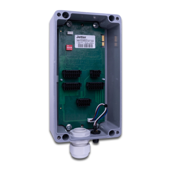
Jetter AG Product description | 3 3 Product description 3.1 Design Fig. 1: Design Fastening screws for attaching the lower part Mounting lugs Housing (cover) 5-pin M12 connector M25 cable gland PCB with 5 connectors and a DIP switch jxm-io-ew30_ba_2151_manual 8 / 56... -
Page 9: Features
■ Separate connections for logic and output driver supply ■ Total current output of up to 25 A 3.3 Diagnostic capability via LEDs The JXM-IO-EW30-G27 has two LEDs that indicate various states and errors. LEDs Blinking pattern Description LED, right... -
Page 10: Nameplate
Jetter AG Product description | 3 LEDs Blinking pattern Description LED, right 3 times ON/OFF, 200 ms The measured values are outside the defined range. LED, left ON: 400 ms The following errors may have occurred: ■ The PCB temperature OFF: 400 ms is too high. -
Page 11: Technical Specifications
183 / 1182* 211 / 209* Fig. 3: Dimensions in mm As the housing of the JXM-IO-EW30-G27 is conically shaped, some dimensions are reduced downwards (tolerance according to GTA 13/5 DIN 1688). These di- mensions are marked with an * in the figure. -
Page 12: Electrical Properties
Jetter AG Technical specifications | 4 4.3 Electrical properties Power supply of Parameter Description output drivers Abbreviation VBAT_PWR Total current 25 A max. Operating voltage 8 … 32 V DC Protection against polarity There is a danger of a short circuit if the polarity is re- reversal versed. -
Page 13: Emc Values
Jetter AG Technical specifications | 4 4.5 EMC values The device has E1 approval according to ECE R10 Rev. 5 and CE conformity ac- cording to ISO 14982. Pulses to ISO Test pulse Values Functional class 7637-2 -450 V +37 V +20 V -150 V... -
Page 14: Outputs
Jetter AG Technical specifications | 4 4.6 Outputs Output PWMi_H3 Parameters Description High-side PWM output with precise current diagnostics Abbreviation PWMi_H3 Quantity 4 pcs. Peak Current 3 A per channel Load range 0.02 A ... 3 A per channel Properties... - Page 15 Jetter AG Technical specifications | 4 Parameters Description Use as input PNP input or NPN input NPN and PNP input Switching the interface to NPN or PNP affects the entire PWM_H7_x group! L level ≤ 1.6 V H level ≥ 4.6 V Input resistance PNP 94 kΩ...
-
Page 16: Current Diagnostics At The Outputs
4.7 Inputs Within the operating voltage range, all inputs are voltage-proof and overcurrent protected. The JXM-IO-EW30-G27 has 3 separate VEXT_SEN connector pins which should be used to supply the sensors. The connector pins output the bat- tery voltage via a PTC thermistor. The output voltage can be read back in the de- vice so that a failure of the sensor supply can be detected. - Page 17 Jetter AG Technical specifications | 4 Analog inputs Category Description Analog inputs Abbreviation AI Quantity 8 pcs. Resolution 12 bits Voltage measuring Rated measuring range 0 ... 5 V Exception: DIP switch slider 1 ON: AI_7 = 0 ... 10 V (high range) DIP switch slider 2 ON: AI_8 = 0 ...
- Page 18 Jetter AG Technical specifications | 4 Configuration in- Configuration inputs are tristate inputs and are used to set the node ID. The base puts address can be set by the user and has the default value 0x30. The node ID can be shifted by connecting the configuration inputs with VBAT_ECU or GND via an offset.
-
Page 19: Mechanical Installation
5.2 Allowed mounting orientations When installing the JXM-IO-EW30-G27, make sure that the environment of the 5- pin M12 connector is protected from dust and water as best as possible. Do not install the unit with the connector facing up. In addition, make sure that the M25 cable gland is firmly tightened to maintain the IP protection class. -
Page 20: Electrical Connection
Jetter AG Electrical connection | 6 6 Electrical connection Improving electromagnetic compatibility NOTICE Improper implementation of the wiring harness may impair electromagnetic com- patibility. ► Keep the cables as short as possible. ► Lay power lines and signal lines separated from each other. -
Page 21: Pin Assignment
Jetter AG Electrical connection | 6 6.1 Pin assignment 6.1.1 Printed Circuit Board 16 14 12 10 8 15 13 11 16 14 12 10 8 16 14 12 10 8 15 13 11 15 13 11 12 10 8 Fig. 5: PCB - pin assignment (top view) - Page 22 Jetter AG Electrical connection | 6 DIP switch slider [} 24] Connector 1 Connector 2 Connector 3 Connector 4 Connector 5 Connector 6 4-pole JST connector (male) 5-pin M12 connector [} 25] (male) M25 cable gland Abbreviations used Abbreviation Description in this document...
- Page 23 Jetter AG Electrical connection | 6 Parameter Description Connector (connection For conductors type) Mismating protection Locking of plug-in connec- Locking lever tion Counterpart to 12- Parameter Description pin WAGO connec- Manufacturer WAGO tor (connection 4, Manufacturer part number 713-1106/037-000 Printed Circuit...
-
Page 24: Dip Switch
Jetter AG Electrical connection | 6 Parameter Description Connector (connection For conductors type) Mismating protection Locking of plug-in connec- Locking lever tion 6.1.1.2 4-pin connector housing The following housing is the compatible counterpart of the 4-pin JST connector: Parameter Description Manufacturer Manufacturer part no. -
Page 25: 5-Pin Male Connector M12
Jetter AG Electrical connection | 6 6.1.3 5-pin male connector M12 Fig. 7: M12 plug, 5-pin, A-coded Signal Description n.c. Reserved VBAT_ECU Power supply ECU GND_ECU Ground for GND_PWR CAN_H CAN High CAN_L CAN Low jxm-io-ew30_ba_2151_manual 25 / 56... -
Page 26: Identification And Configuration
Jetter AG Identification and Configuration | 7 7 Identification and Configuration 7.1 Identification This chapter describes how to identify the JXM-IO-EW30-G27: ■ Determining the hardware revision ■ Retrieving Electronic Data Sheet (EDS) information. The EDS holds numerous non-volatile production-relevant data. -
Page 27: Electronic Data Sheet (Eds)
Jetter AG Identification and Configuration | 7 7.1.2 Electronic Data Sheet (EDS) Each JXM-IO-EW30-G27 has an Electronic Data Sheet (EDS). Production-spe- cific data is stored in the indices 0x4555 and 0x4565. EDS information Index Subindex Description Type Type of access... -
Page 28: Operating System Update Of The Expansion Module
By means of the controller ■ By means of the command line tool JetEasyDownload (version 1.00.0.15 or higher) from Jetter 7.2.1.1 Operating system update via JetEasyDownload You can update the operating system file of the device using a Peak CAN dongle and the command line tool JetEasyDownload (version 1.00.0.15 or higher) by... - Page 29 Jetter AG Identification and Configuration | 7 Performing the up- JetEasyDownload -H100 -T48 -B5 -S8000 -LJXM-IO-EW30-G27.os date ü JetEasyDownload and Peak CAN dongle must be ready for use. ü There must be a CAN connection between Peak CAN dongle and JXM-IO- EW30-G27.
-
Page 30: Programming
8 Programming 8.1 Concept and control The concept of the JXM-IO-EW30-G27 is based on the assignment of interfaces to the inputs and outputs of the device. Each input and output of the device is called a port and can be config- ured. -
Page 31: Io Ports And Sdo Map
Jetter AG Programming | 8 Ports Description Supported interfaces DO_H3_1 … DO_H3_4 Digital outputs DO_HS3 DI_NPN, DI_PNP Tab. 24: Supported ports and interfaces - Overview When configuring the outputs, observe the information in chapter Outputs [} 14]. 8.1.2 IO ports and SDO map... -
Page 32: Available Interfaces, Parameters, Values And Statuses
Jetter AG Programming | 8 8.1.3 Available interfaces, parameters, values and statuses INFO Restrictions The following restrictions must be observed in the Operational and Pre- Operational states: ■ You can only assign an interface in the Pre-Operational state during the startup process. - Page 33 Jetter AG Programming | 8 Interface Parameter Values Status Dez/Hex PWMO_HS3 PWM_FRQ O_DUTY_CYCLE OVERCURRENT High-side PWM DITHER_FRQ I_HCURRENT SUPPLY_FAULT output (up to 3 A; DITHER_AMP ERROR with precise cur- MAX_CURRENT INACTIVE rent measure- ment) OVERCURRENT_TIME OPEN_CIRCUIT FILTER_DEEP MIN_DEVIATION MIN_CURRENT OPENCIRCUIT_DETEC-...
- Page 34 Jetter AG Programming | 8 Interface Parameter Values Status Dez/Hex 11/b PWMO_HS7 PWM_FRQ O_DUTY_CYCLE OVERCURRENT High-side DITHER_FRQ I_HCURRENT SUPPLY_FAULT PWM output DITHER_AMP ERROR (up to 7 A) MAX_CURRENT INACTIVE OVERCURRENT_TIME OPEN_CIRCUIT FILTER_DEEP MIN_DEVIATION MIN_CURRENT OPENCIRCUIT_DETEC- TION SENSOR_SUPPLY 12/c DO_HS7 MAX_CURRENT...
-
Page 35: Io Interfaces
Jetter AG Programming | 8 8.1.4 IO interfaces IO interface input values Type Unit/ Subindex Description Type of ac- value range cess I_VOLTAGE Voltage value 1 mV I_RATIO Ratio to battery voltage 1 ‰ (per mil) I_CURRENT Current value (small measuring 1 µA... - Page 36 Jetter AG Programming | 8 IO interface parameters Type Unit/ Subindex type Description of ac- value range cess SENSOR_SUPPLY Associated sensor supply, U16 R/W 0 … 3 which is also monitored. PWM_FRQ PWM frequency U32 R/W 0.1 Hz Default: 1 kHz...
- Page 37 Jetter AG Programming | 8 Type Unit/ Subindex type Description of ac- value range cess MIN_CURRENT If less current flows at the U16 R/W 1 mA output than the set threshold, this is detected as a cable The default break and the condition is set...
-
Page 38: Setting The Node Id
Jetter AG Programming | 8 Status of IO interface Status Description 0x00000001 INACTIVE This port is disabled. 0x00000002 ERROR An undefined error has occurred. 0x00000004 CONFIG A configuration error has occurred. 0x00000008 OVERVOLTAGE Overvoltage is present at the input. 0x00000010 OVERCURRENT Overcurrent is present at the input/output. -
Page 39: Diagnostic Information
Jetter AG Programming | 8 8.3 Diagnostic information Diagnostic information Type Index Subindex Description Type of ac- Unit cess 0x2000 Number of supported entries VBAT_PWR 7V IO PCB temperature 0.1 °C CPU temperature 0.1 °C CPU VRef SPWR1 SPWR2 SPWR3... -
Page 40: Saving Settings Permanently And Resetting To Default Values
3. The vehicle controller reads the CRC via index 0x4556, subindex 1 and saves this value locally in a remanent memory. 4. After a restart of the JXM-IO-EW30-G27 the vehicle controller compares the locally stored CRC value with the value in index 0x4556, subindex 1. If the values do not match, parameterization must be restarted. -
Page 41: System Parameters
Jetter AG Programming | 8 8.5 System parameters Type Subinde Default Index Description Type of ac- value cess 0x4556 Number of supported entries CRC of the current parameter settings This makes it possible to check whether the settings have to be transferred to the device again. - Page 42 Jetter AG Programming | 8 8.6.1 RPDO communication parameters Subind Type of Index Description Type Unit Default value access 0x1400 Number of sup- … ported entries 0x1403 COB ID (user- U32 R/W Index 0x1400 0x200 + node configurable value for PDOs)
-
Page 43: Mapping Tables
Jetter AG Programming | 8 8.6.3 Mapping tables RPDO mapping table Subind Type of Index Description Type Default value access 0x1600 Number of supported entries … First object that is mapped 0x1603 Second object that is mapped … 64. Object to be mapped Tab. 39: RPDO mapping table... - Page 44 Jetter AG Programming | 8 8.6.4 Mapping of digital values As an alternative to bit-wise mapping of digital values to PDOs, you can also use object 0x6000 for mapping digital values. Type of Default Index Subindex Description Type access value...
-
Page 45: Stx Example: Output Value Ai1 Voltage To Tpdo1
Jetter AG Programming | 8 8.6.5 STX example: Output value AI1 Voltage to TPDO1 The following STX example shows you in part how you can output the value AI1 Voltage on TPDO1. //Switching JXM-IO-EW30-G27 to PREOPERATIONAL CanOpenSetCommand( cCanChannel,CAN_CMD_NMT,CAN_CMD_NMT_Value( cJXMNodeId,CAN_NMT_PREOPERATIONAL)); //AI 1 Port Type to AI_VOLTAGE (=1) iTemp := 1;... -
Page 46: Frequency Measurement At The Digital Inputs
Jetter AG Programming | 8 8.7 Frequency measurement at the digital inputs For the frequency measurement at the digital inputs 2 measuring methods are available: ■ Gating measurement ■ Pulse length measurement Gating measurement The gate time (GATE_TIME) is the time period during which pulses are counted. Measurements of high-frequency signals can thus be easily recorded. -
Page 47: Acquisition Of Encoder Signals
Jetter AG Programming | 8 8.8 Acquisition of encoder signals The ENCI_PNP interface lets you acquire encoder signals. 2 inputs are required for the acquisi- tion. For example, if you configure input DI_P_3 as ENCI_PNP, the adjacent input DI_P_4 is also assigned automatically. -
Page 48: Troubleshooting
Jetter AG Programming | 8 8.9 Troubleshooting Emergency object telegrams (EMCY telegrams) EMCY telegrams are sent at startup or after any changes at an inhibit time of 50 ms. Byte Contents 0 … 1 = Emergency Error Code 2 = Error register... -
Page 49: Heartbeat
The individual P, I and D controllers usually have the following characteristics: Fig. 9: Comparison of controller types in a control loop Step response Time 8.10.1 Test scenario The PID controller was tested on JXM-IO-EW30-G27 the under the following conditions: Condition Description Output 1 kHz PWM... - Page 50 Jetter AG Programming | 8 JetSym was used to set up a test scenario in which the setpoint switches back and forth between 0.3 A and 0.7 A. Closed-loop control parameters: P=100,000, I=0, D=0, Measurements: blue=setpoint, red=actual value Fig. 10: Test scenario with the control parameters P=100,000, I=0, D=0 The P controller works well with this value.
- Page 51 Jetter AG Programming | 8 The I controller also works satisfactorily, the setpoint is reached with this setting. Closed-loop control parameters: P=100,000, I=5,000, D=400, Measurements: blue=setpoint, red=actual value Fig. 12: Test scenario with the control parameters P=100,000, I=5,000, D=400 The D controller causes the actual value to approach the setpoint more quickly.
-
Page 52: Current Measurement At The Pwmi_H3_X Outputs
Jetter AG Programming | 8 8.10.2 Current measurement at the PWMi_H3_X outputs The current measurement at the PWMi_H3_X outputs is implemented via shunt resistor. The measuring amplifier has a low-pass filter with R*C = 1 ms. This low-pass filter provides an inte- gral component. -
Page 53: Maintenance And Repairs
In case of damaged packaging inspect the device for any visible damage, and in- form your freight forwarder and the Jetter AG of the damage caused during ship- ment. If the device is damaged or has been dropped, it is strictly forbidden to use... -
Page 54: Service
To contact them, please call our technical hotline or use the contact form on our homepage: Technical hotline | Jetter - We automate your success. You are also welcome to send an e-mail to our technical hotline: hotline@jetter.de... -
Page 55: Spare Parts And Accessories
Inadequate accessories might cause damage to the product NOTICE Parts and equipment from other manufacturers might impede the function of the device and cause damage to the product. ► Only use accessories recommended by Jetter AG. jxm-io-ew30_ba_2151_manual 55 / 56... - Page 56 Jetter AG Graeterstrasse 2 71642 Ludwigsburg www.jetter.de E-mail info@jetter.de Phone +49 7141 2550-0 We automate your success.