
Related Manuals for Lars Thrane LT-1000 NRU


Summary of Contents for Lars Thrane LT-1000 NRU
- Page 1 User & Installation Manual LT-1000 NRU Document Number: 95-100178 REV. 1.00 Release date: January 19, 2016 Copyright © Lars Thrane A/S Denmark ALL RIGHTS RESERVED...
- Page 3 Manuals issued by Lars Thrane A/S are periodically revised and updated. Anyone relying on this information should acquire the most current version e.g. from Lars Thrane A/S. Lars Thrane A/S is not responsible for the content or accuracy of any translations or reproductions, in whole or in part, of this manual from any other source.
- Page 4 Failure to comply with these precautions or with specific warnings elsewhere in this manual violates safety standards of design, manufacture and intended use of the equipment. Lars Thrane A/S assumes no liability for the customer's failure to comply with these requirements. Instructions for the Installer...
- Page 5 IMPORTANT: Text marked ‘Important’ provides essential information to the reader, and is key information to the user in order for the equipment to work properly. Personnel injury or damage to the equipment can occur if instructions are not followed. Lars Thrane A/S www.thrane.eu...
- Page 6 About this manual Intended readers This is a User & Installation Manual for LT-1000 Navigation Reference Unit, LT-1000 NRU. The manual is primarily intended for installers and service personnel. Personnel installing or servicing the system should be professionals, with technical expertise, properly trained, and likewise authorized.
- Page 7 LT-1000 User & Installation Manual Record of Revisions Rev. Description Release Date Initials 1.00 Original document January 19, 2016 Lars Thrane A/S www.thrane.eu...
-
Page 8: Table Of Contents
APP. C – SPECIFICATIONS ........................37 APP. D - NMEA 0183 SENTENCES ......................38 APP. E - NMEA 2000 PGNS ........................40 APP. F – LT-SERVICE TOOL (COMMANDS) ..................41 APP. G - DECLARATION OF CONFORMITY ..................42 Lars Thrane A/S www.thrane.eu... -
Page 9: Introduction
The LT-1000 NRU makes use of the latest technology within GNSS receivers, with market leading acquisition and tracking performance. The LT-1000 NRU is designed and built for the demanding and rough environment at sea and with an operational ambient temperature range from -40⁰C to +55⁰C (-40⁰F to +131⁰F). - Page 10 It is recommended to use the entire LT-1000 User & Installation Manual as guidance for the best possible and complete installation. Lars Thrane A/S www.thrane.eu 2 of 42...
-
Page 11: Quick Installation Guide
Installation Manual for Safety Instructions. · Unit Test Sheet Installation The LT-1000 NRU DIP-switch is configured to 4.800 baud (NMEA 0183) and ‘Open’ (NMEA 2000) from the factory. Alternative DIP-switch settings are 38.400 baud (NMEA 0183) and ‘Terminated’ (NMEA 2000). Mounting considerations: ·... - Page 12 Keep a steady course (± 5°) for min. 10 s. SOG: 2–12 knots IMPORTANT: If the LT-1000 NRU is physically moved or rotated, it is required to perform a new calibration. Refer to the LT-1000 User & Installation Manual on how to use the LT-Service Tool to verify a subsequent calibration.
-
Page 13: Installation
WARNING: To avoid electric shock, do not apply power to the LT-1000 NRU if there is any sign of shipping damage to any part of the unit or the outer cover. Read the Safety Instructions at the front of this manual before installing or operating the unit. - Page 14 Pole or Roof Mount installation It is possible to use either a pole or roof mount, when installing the LT-1000 NRU, see Figure 4 (roof mount) and Figure 5 (pole mount).
- Page 15 LT-1000 User & Installation Manual Installation Pole Mount installation Step 1: Unpack the LT-1000 NRU and make a record of the unit serial number for support or warranty issues that could occur in the future. 6: P LT-1000 NRU) IGURE...
- Page 16 IMPORTANT: Make sure that there are no magnetic disturbances (see Mounting and installation considerations on page 5 for for details) or compass within 0.3 m. (1 ft.) of the LT-1000 NRU. Mount the LT-1000 NRU at least 1 m. away from VHF, UHF, MF-HF, Inmarsat, Iridium, etc.
- Page 17 LT-1000 User & Installation Manual Installation 11: P IGURE OLE MOUNT INSTALLATION STEP LOCATE AN APPROPRIATE LOCATION Lars Thrane A/S www.thrane.eu 9 of 42...
- Page 18 LT-1000 User & Installation Manual Installation 12: P IGURE OUNT INSTALLATION STEP LOCATE AN APPROPRIATE LOCATION 13: P IGURE OUNT INSTALLATION STEP LOCATE AN APPROPRIATE LOCATION Lars Thrane A/S www.thrane.eu 10 of 42...
- Page 19 Step 5: Complete the internal or external cable routing. Feed the communication cable through the pole mount and install the cable plug. 14: P 5 (I IGURE OUNT INSTALLATION STEP NTERNAL ROUTING OF THE COMMUNICATION CABLE Lars Thrane A/S www.thrane.eu 11 of 42...
- Page 20 LT-1000 User & Installation Manual Installation 15: P 5 (E IGURE OUNT INSTALLATION STEP XTERNAL ROUTING OF THE COMMUNICATION CABLE Lars Thrane A/S www.thrane.eu 12 of 42...
- Page 21 LT-1000 User & Installation Manual Installation Step 6: Fasten the pole mount by securing the two stainless A4 screws onto the LT-1000 NRU as illustrated in Figure 16. 16: P IGURE OUNT INSTALLATION STEP SECURING THE TWO STAINLESS SCREWS Lars Thrane A/S www.thrane.eu...
- Page 22 LT-1000 User & Installation Manual Installation Step 7: Adjust the heading direction of LT-1000 NRU before fastening the pinol screw in the pole mount. NOTE: Final precision tuning of the Heading offset can be performed using the LT-service tool, see Configuration using LT-Service on page 29.
- Page 23 Step 1: Locate an appropriate location for the roof mount installation. IMPORTANT: Make sure that there are no magnetic disturbances (see Mounting and installation considerations on page 5 for details) or compass within 30 cm / 1 ft. of the LT-1000 NRU. 18: R...
- Page 24 LT-1000 User & Installation Manual Installation Step 3: Unpack the LT-1000 NRU and make a record of the unit serial number for support or warranty issues that could occur in the future. 20: R LT-1000 NRU) IGURE OUNT INSTALLATION BOTTOM SIDE OF THE Step 4: Remove cap for DIP-switch setting.
- Page 25 OUNT INSTALLATION STEP SWITCH AND Step 6: Mount and secure the two stainless A4 screws (with securing disc) from the pole mount. 23: R IGURE OUNT INSTALLATION STEP SECURE THE TWO STAINLESS SCREWS Lars Thrane A/S www.thrane.eu 17 of 42...
- Page 26 Step 7: Adjust the heading before final clamping of the two self-cutting stainless screws. 24: R IGURE OUNT INSTALLATION STEP FINAL CLAMPING OF THE TWO SELF CUTTING STAINLESS SCREWS Step 8: Connect the communication cable. 25: R IGURE OUNT INSTALLATION STEP CONNECT THE COMMUNICATION CABLE Lars Thrane A/S www.thrane.eu 18 of 42...
- Page 27 Step 9: Install the simple-cut end of the communication cable according to the details provided in Connecting on page 20. 26: R 9 (I IGURE OUNT INSTALLATION STEP NSTALL THE SIMPLE END OF THE COMMUNICATION CABLE Lars Thrane A/S www.thrane.eu 19 of 42...
-
Page 28: Connecting
The LT-1000 NRU has an 8-pin M12 female connector, which is supporting simultaneously data on NMEA 0183 and NMEA 2000. The placement of the LT-1000 NRU connector is illustrated on Figure 27. A detailed connector pin out with pin numbering is illustrated in Figure 28. - Page 29 DIP-switch and LEDs The LT-1000 NRU has a built-in DIP-switch, which is accessible from the bottom side of the unit, before the pole or roof mount is mounted. To access the DIP-switch, the cap plug has to be removed; hereafter the installer will have direct access to configuration of the DIP-switch.
- Page 30 Connecting Connecting to NMEA 0183 If connecting the LT-1000 NRU to a NMEA 0183 device, then it is only required to connect the transmit part of the NMEA 0183 wires TxD+ (Brown) and TxD- (Yellow) from the communication cable. NOTE: Make sure that the LT-1000 NRU is configured for the desired baud rate (4800 or 38400 baud), see DIP-switch and LEDs on page 21.
- Page 31 Connecting to NMEA 2000 If connecting the LT-1000 NRU to a NMEA 2000 network (i.e. backbone) then it is required to use a screw-in connector as illustrated in Figure 34. The screw-in connector is in-the-box together with the LT-1000 NRU.
- Page 32 LT-1000 NRU to a NMEA 2000 network (backbone). NMEA 2000 (‘Open’) If the LT-1000 NRU is installed as illustrated in Figure 37, then the DIP-switch must be configured to ‘Open’. For correct configuration of the DIP-switch, see DIP-switch and LEDs on page 21. The LT-1000 NRU is connected to the NMEA 2000 backbone using a drop-cable.
- Page 33 LT-1000 NRU (both Tx and Rx directions). Use either a ‘USB to RS-422 converter’ or connect a serial port directly to the LT-1000 NRU as described in the following sub-sections. The LT-1000 NRU requires an input voltage of 9-40 VDC. Most of the USB to RS- 422 converter’s and serial interfaces are only providing 5 VDC.
- Page 34 Connecting Serial Port (RS-422) Illustration of a RS-422 interface in between a serial port and the LT-1000 NRU for providing a communication link for the LT-Service Tool, see Figure 40. The RS-422 interface is balanced and more robust than an unbalanced serial interface, which is illustrated in Figure 41.
-
Page 35: Deviation Calibration
Deviation calibration Deviation calibration The magnetometer sensors in the LT-1000 NRU may be affected by magnetic disturbances from the vessel, which needs to be corrected in order to deliver magnetic heading (and thus true heading). The source of these magnetic disturbances could be, but not limited to; engines, power cables, etc. This discrepancy between magnetic and compass heading is called the “deviation”. - Page 36 Configuration using LT-Service Tool on page 29 and Mounting offset adjustment on page 31. IMPORTANT: If the LT-1000 NRU is physically moved or rotated, it is required to perform a new calibration. Otherwise, the deviation calibration will not be valid.
-
Page 37: Configuration Using Lt-Service Tool
The LT-Service Tool is an optional PC program, which can be used together with the LT-1000 NRU. It is possible to install the LT-1000 NRU and use it for navigational purposes, without configuration by the LT-Service Tool. The LT-Service Tool is intended for installation and service by trained personnel. - Page 38 Continuous Monitoring (CM) o General status · Monitoring of NMEA 0183 data o Live NMEA 0183 sentences (to inspect valid output from the LT-1000 NRU device) · Live navigations data o Navigation window to display live data (up-date-rate = 1 second) ·...
- Page 39 ECEIVER ONFIGURATION Mounting offset adjustment To get the best possible performance with the LT-1000 NRU, it is required to perform a mounting offset adjustment after physical installation of the device, see procedure below. Mounting offset procedure: 1) Physical installation of LT-1000 NRU (this includes heading alignment with the centerline of the ship).
-
Page 40: Service And Repair
For troubleshooting the LT-1000 NRU, see Troubleshooting on page 33. If the LT-1000 NRU for some reason does not work as described in this manual, make contact to the distributor or dealer, from where the product was originally bought. The distributors or dealers will have experience and know-how to assist with further technical support and troubleshooting. -
Page 41: Troubleshooting
For further details on the DIP-switch, see on page 21. 5) Using NMEA 2000 - check your navigational equipment for correct selection of the LT-1000 NRU as preferred source (Heading, GPS, Environmental). Check that the LT-1000 NRU is supporting the expected NMEA 2000 PGNs;... -
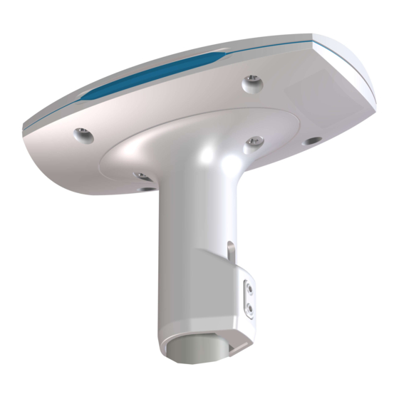
Page 42: App. A - Outline Drawings
LT-1000 User & Installation Manual App. A - Outline Drawings App. A - Outline Drawings LT-1000 with Pole Mount Lars Thrane A/S www.thrane.eu 34 of 42... - Page 43 LT-1000 User & Installation Manual App. A - Outline Drawings LT-1000 Roof Mount Lars Thrane A/S www.thrane.eu 35 of 42...
-
Page 44: App. B - Performance
2: The dynamic heading accuracy is specified with roll/pitch less than ± 45° and ROT ≤ 45°/s. 3: The LT-1000 NRU has an immunity filter against Iridium and Inmarsat transceivers 4: Solar radiation and environmental conditions will affect the measured air temperature... -
Page 45: App. C - Specifications
LT-1000 User & Installation Manual App. C – Specifications App. C – Specifications LT-1000 NRU Specifications Certification and standards CE, IEC 60945, IEC 60950, EN 300 440, EN 301 389, FCC, IC, RoHS, WEEE NMEA 0183, NMEA 2000 Equipment class... -
Page 46: App. D - Nmea 0183 Sentences
LT-1000 User & Installation Manual App. D - NMEA 0183 Sentences App. D - NMEA 0183 Sentences The LT-1000 NRU is compliant with version 4.00 of the NMEA 0183 standard. The following table lists the supported sentences. NMEA 0183 Sentences... - Page 47 The GSV sentence will never be sent with Talker Identifier GN as it will ever only contain data from one GNSS system. If the LT-1000 NRU is configured to use multiple GNSS systems, the GSV sentence will be repeated for each GNSS system and the Talker Identifier of each GSV sentence will indicate the specific GNSS system to which it applies.
-
Page 48: App. E - Nmea 2000 Pgns
App. E - NMEA 2000 PGNs App. E - NMEA 2000 PGNs The LT-1000 NRU is compliant with version 2.000 of the NMEA 2000 standard and version 2.000 of the NMEA Network Database. The following table lists the supported PGNs. -
Page 49: App. F - Lt-Service Tool (Commands)
LT-1000 User & Installation Manual App. F – LT-Service Tool (commands) App. F – LT-Service Tool (commands) Lars Thrane A/S www.thrane.eu 41 of 42... -
Page 50: App. G - Declaration Of Conformity
LT-1000 User & Installation Manual App. G - Declaration of Conformity App. G - Declaration of Conformity Lars Thrane A/S www.thrane.eu 42 of 42...