Table of Contents
Advertisement
Quick Links
Advertisement
Table of Contents

Related Manuals for Electrolux CLASSIC 1


Summary of Contents for Electrolux CLASSIC 1
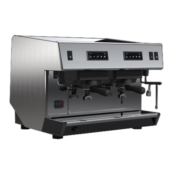
- Page 1 CLASSIC 123 Service Manual RB9912- 2020.05 *Original instructions...
- Page 2 Foreword The installation, use and maintenance manual (hereinafter Manual) provides the user with information necessary for correct and safe use of the machine (or “appliance“). The following must not be considered a long and exacting list of warnings, but rather a set of instructions suitable for improving machine performance in every respect and, above all, preventing injury to persons and animals and damage to property due to im- proper operating procedures.
-
Page 3: Table Of Contents
Contents A SAFETY INFORMATION ......................... 5 General information ........................5 General safety ..........................5 Personal protection equipment ......................6 Transport, handling and storage ...................... 6 Installation and assembly ....................... 7 Water connection.......................... 7 Electrical connection ........................7 Use ............................8 appliance cleaning and maintenance .................... - Page 4 MAINTENANCE ..........................19 Preventive maintenance....................... 19 K TROUBLESHOOTING .......................... 20 Faults reported by the electronic display ..................20 K.1.1 Problems related to the electronic box control keys..............20 K.1.2 Problems of fuses ......................20 K.1.3 Dosing problems....................... 20 K.1.4 Other faults........................22 K.1.5 Level adjustment problems....................
-
Page 5: Asafety Information
SAFETY INFORMATION General information To ensure safe use of the appliance and a proper understanding of the manual it is necessary to be familiar with the terms and typographical conventions used in the documentation. The following symbols are used in the manual to indicate and identify the various types of hazards: WARNING Danger for the health and safety of operators. -
Page 6: Personal Protection Equipment
Personal protection equipment Summary table of the Personal Protection Equipment (PPE) to be used during the various stages of the machine's service life. Stage Protective Safety Gloves Glasses Safety garments footwear helmet — ● ○ — ○ Transport — ● ○... -
Page 7: Installation And Assembly
Installation and assembly • The installation must be carried out by a specialised personnel. • Follow the installation instruction supplied with the appliance. • Do not install a damaged appliance. Any missing or faulty parts must be replaced with original parts. •... -
Page 8: Use
isolation fault in the TN or TT systems or, for IT systems, the use of isolation controllers or differential current protection devices to activate automatic power disconnection (an isolation controller must be provided for indicating a possible first earth fault of a live part, unless a protection device is supplied for switching off the power in case of a such a fault. -
Page 9: Machine Disposal
– inadequate or interrupted water supply, steam, air, gas subject to local terms and conditions. (including impurities and/or other that does not comply Check on Electrolux Professional website the list of authorized with the technical requirements for each machine); customer care. -
Page 10: Safety Signs To Be Placed On The Machine Or Near Its Area
Safety signs to be placed on the • placing in the machine any objects or things not compatible with its use, or that can damage the machine, cause injury machine or near its area or pollute the environment; Prohibition Meaning •... -
Page 11: Dgeneral Information
Water Pressure MPa. Water Pressure max port personnel. Manufacturer Electrolux Professional SpA or any other The data plate gives the product identification and technical service centre authorised by Electrolux data. The meaning of the various information given on it is Professional SpA. -
Page 12: Additional Indications
This manual is intended solely for consultation by the operator and can only be given to third parties with the permission of Additional indications Electrolux Professional SpA. The drawings and diagrams given in the manual are not in scale. They supplement the written information with an outline,... -
Page 13: Ftechnical Characteristics
TECHNICAL CHARACTERISTICS Data table MODELE CLASSIC 1 CLASSIC 2 CLASSIC 3 Width 343 mm [13.5″] 642 mm [25.2″] 862 mm [33.9″] Height 508 mm [20″] 508 mm [20″] 508 mm [20″] Depth 568 mm [22.3″]... -
Page 14: Draining
• Tube: internal ⌀8 mm [0.3″] minimum • Provide a shut-off tap • Work on the right side of the appliance: • Unscrew the cruciform screw at the front of the side • Slide the side toward the back • Screw the water inlet tube to the connection in the appliance G.2.2 Draining The appliance is delivered with a complete connection kit including a stainless steel braided water hose 2 m [78.7″] length and a... -
Page 15: Electrical Connection
Electrical connection None of the switches on the appliance must be on. Check that the values of the voltage, frequency and power shown on the technical information plate of the appliance match those of the mains. Put the switch of the appliance on position 0. The appliance is delivered with a cable of 3 or 5 numbered wires (including the earth wire). -
Page 16: Adjusting The Expansion Valve
G.4.2 Adjusting the expansion valve 1 group model The High pressure valve is located on the right side of the appliance: it is necessary to dismantle the right side. The valve is set above the pump; its adjusted pressure must just be greater than the water network pressure. -
Page 17: Keyboards
on and the boiler level is set automatically. The water-intake H.3.3 Pr = Manual programming indicator blinks to show that the boiler is filling. Same proceeding as in calculated programming Pc. Heating: • The manual programming doesn’t calculate the other doses When the water-intake indicator stops blinking, put the switch (1, 2 or 3 cups), only the programmed dose is modified. -
Page 18: How To Prepare A Cappuccino
• Keep the end-piece of the steam tube at the surface to • Press the two keys at the same time, and at the obtain a fine foam. same time, switch the appliance back on. • After each use, clean the steam tube with a wet rag and •... -
Page 19: Jmaintenance
MAINTENANCE Preventive maintenance Quantity Frequency Reference 1st, 3rd 2nd & Description 1 group 2 groups 3 groups & 5th ELUX 6 month year years years Group service 0UN122 GASKET - 2.62 X 52.07 27800 0UN128 HEAD GASKET 9MM PC17 0UN131 GICLEUR ⌀0.7 KIT 23127 WASHER DIFFUSER... -
Page 20: Ktroubleshooting
TROUBLESHOOTING SAFETY INFORMATION A. Switch off the machine before any work on the electrical circuits. B. Cool the machine and make the pressures drop before any work on the hydraulic circuit. Faults reported by the electronic display K.1.1 Problems related to the electronic box control keys If the display shows this means that the corresponding key is short-circuited and is no longer usable. - Page 21 K.1.3.2 Counting safety During the infusion, the display shows . this means that the doser has no longer sent pulses to the electronic box of the group for 5 seconds. If the interruption of counting has only been momentary, the infusion will be stopped when the number of pulses counted will correspond with the programmed number of pulses.
-
Page 22: Other Faults
K.1.4 Other faults K.1.4.1 Water problems of the coffee unit Doses below the programmed doses The doses obtained are lower than the programmed doses The leak is located after the volumetric doser The 3-way solenoid valve of the group is leaking One of the fittings located after the output from the during decompression during the infusion. -
Page 23: Level Adjustment Problems
K.1.4.4 Bad decompression After infusion, when you remove the cup, the coffee ground disk is wet The passing time is too short: Decompression circuit • Grinding too coarse The temperature is too low plugged • Dose too low • Pressure too low Check: Check: •... -
Page 24: Unable To Programme
K.1.6 Unable to programme Programming is impossible Display of a safety signal: • Safety key Check the unit configuration • A0: Programming prohibited • : Fuse • A1: Programming permitted • : Time • : Doser Refer to the corresponding paragraph for repair K.1.7 The “heating doesn't follow •... -
Page 25: Lrelated Documents
RELATED DOCUMENTS Wiring diagrams Fig. 2 Wiring diagram for CLASSIC 1 [230V MONO]... - Page 26 Fig. 3 Wiring diagram for CLASSIC 2 [230V MONO]...
- Page 27 Fig. 4 Wiring diagram for CLASSIC 2 [380V TRI]...
- Page 28 Fig. 5 Wiring diagram for CLASSIC 3 [230V MONO]...
- Page 29 Fig. 6 Wiring diagram for CLASSIC 3 [380V TRI]...
- Page 32 Electrolux Professional SPA Viale Treviso 15 33170 Pordenone www.electroluxprofessional.com...