Table of Contents
Advertisement
Quick Links
Advertisement
Table of Contents

Related Manuals for Honeywell Signalpoint Pro


Summary of Contents for Honeywell Signalpoint Pro
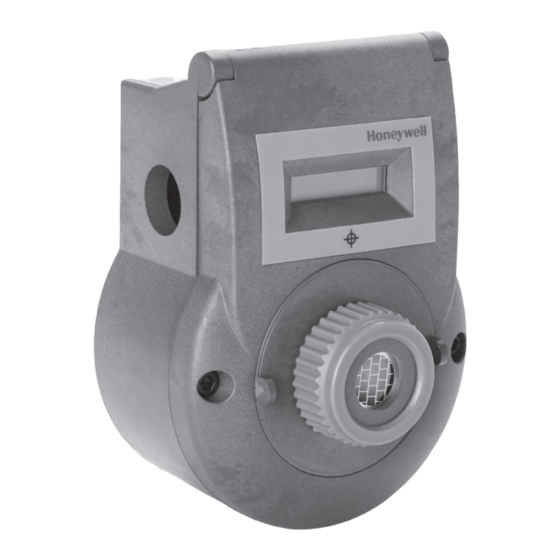
- Page 1 Technical Manual Signalpoint Pro...
-
Page 2: Safety
Cautions appear in the sections / sub-sections of the document where they apply. WARNINGS SIGNALPOINT PRO IS DESIGNED FOR INTRINSICALLY SAFE INSTALLATION AND USE IN ZONE 1 OR 2 HAZARDOUS AREAS IN EUROPE, AND DIVISION 1 AREA APPLICATIONS IN NORTH AMERICA. -
Page 3: Information
MAN0853 Issue 3 10/08 2 Information Honeywell Analytics can take no responsibility for installation and / or use of its equipment if this is not done in accordance with the appropriate issue and / or amendment of the Operating Manual. -
Page 4: Table Of Contents
SIGNALPOINT PRO OPERATING MANUAL MAN0853 Issue 3 10/08 3 Table of contents 1 Safety......................1 2 Information .....................2 3 Table of contents ...................3 4 Introduction ....................4 4.1 Product overview ..................4 4.1.1 Transmitter....................4 4.1.2 Sensor......................5 4.1.3 Accessories....................5 5 Installation......................6 5.1 Mounting and location of detectors .............7 6 Electrical connections ..................9... -
Page 5: Introduction
1 x 21mm diameter clearance cable / conduit entry and 1 x 21mm diameter clearance knockout allow for incoming cable connections. The output is an industry standard 2 wire IS 4-20mA loop. Signalpoint Pro is suitable for connection to a wide range of Honeywell Analytics or 3 party control equipment. -
Page 6: Sensor
SIGNALPOINT PRO OPERATING MANUAL MAN0853 Issue 3 10/08 magnetic switch target are located on the front of the transmitter lid. The hinged lid opens to reveal the large terminal compartment. Additional user programmable features are made using the pushbuttons on the transmitter electronics assembly located on the inside of the transmitter lid. -
Page 7: Installation
5 Installation WARNINGS SIGNALPOINT PRO IS DESIGNED FOR INTRINSICALLY SAFE INSTALLATION AND USE IN ZONE 1 OR 2 HAZARDOUS AREAS IN EUROPE, AND DIVISION 1 AREA APPLICATIONS IN NORTH AMERICA. INSTALLATION MUST BE IN ACCORDANCE WITH THE RECOGNIZED STANDARDS OF THE APPROPRIATE AUTHORITY IN THE COUNTRY CONCERNED. -
Page 8: Mounting And Location Of Detectors
SIGNALPOINT PRO OPERATING MANUAL MAN0853 Issue 3 10/08 5.1 Mounting and location of detectors Caution: The location of the detectors should be made in accordance with any relevant local and national legislation, standards or codes of practice. Always replace detectors with a detector of the same type. - Page 9 SIGNALPOINT PRO OPERATING MANUAL MAN0853 Issue 3 10/08 21mm diameter 21mm diameter knockout clearance hole 72.5mm (2.85”) 105mm (4.1”) Mounting holes (M3.5 or No.6 screws) Diagram 2: Detector dimensions and mounting hole locations...
-
Page 10: Electrical Connections
Electrical connections WARNINGS SIGNALPOINT PRO IS DESIGNED FOR INTRINSICALLY SAFE INSTALLATION AND USE IN ZONE 1 OR 2 HAZARDOUS AREAS IN EUROPE, AND DIVISION 1 AREA APPLICATIONS IN NORTH AMERICA. INSTALLATION MUST BE IN ACCORDANCE WITH THE RECOGNIZED STANDARDS OF THE APPROPRIATE AUTHORITY IN THE COUNTRY CONCERNED. -
Page 11: Detector Wiring Schematics
SIGNALPOINT PRO OPERATING MANUAL MAN0853 Issue 3 10/08 6.1 Detector wiring schematics Caution: All electrical connections should be made in accordance with any relevant local or national legislation, standards or codes of practice. For European Zone 1 or 2 or North American Class I Division 1 area installation a suitable barrier or Isolator is required (refer to Section 6.3). -
Page 12: Terminal Connections
To calculate the maximum cable lengths, calculate the total capacitance and inductance for the length of cable, add any capacitance or inductance due to the field device (Signalpoint Pro capacitance and inductance = 0). The resulting totals should not be greater than the value shown for the barrier or isolator. -
Page 13: Suggested Barriers And Isolators
Total allowable inductance Ia = Ib-If, Ia = 3.05-0 = 3.05 If the cable type is known, then the parameters from the manufacturer should be used otherwise refer to the Signalpoint Pro control drawing P-1446, page 2 of 2 which suggests values of:- In North American Installations: Cc = 60pF/foot (0.00006 microfarads) and lc = 0.2 microhenries/foot (0.0002... -
Page 14: Cable Screening
SIGNALPOINT PRO OPERATING MANUAL MAN0853 Issue 3 10/08 6.5 Cable screening In order to ensure the cable screen length and diameter is suitable for the terminal, it is recommended that a short length of wire is crimped to the cable shield braid as shown in the diagram below. -
Page 15: Default Configuration
SIGNALPOINT PRO OPERATING MANUAL MAN0853 Issue 3 10/08 7 Default configuration The Signalpoint Pro toxic and Oxygen gas detectors are supplied with the following default configuration. Detector 4-20mA output signal ≤3mA Fault / Under-range Inhibit 4mA (toxic) or 17.38mA (for Oxygen) -
Page 16: First Time Switch On
11. Calibration is mandatory before the detector can be used for gas monitoring. Refer to Section 8.3 Calibration for the proper procedure. Note: The Signalpoint Pro detector will not turn on if powered up within 5 seconds of power off. -
Page 17: Setting Full Scale Detection Range
SIGNALPOINT PRO OPERATING MANUAL MAN0853 Issue 3 10/08 8.1 Setting full scale detection range Each plug in sensor has a default (recommended) full scale detection range. For most sensors this range is user adjustable. The associated controller’s alarm level should not be set less than 3% of the detector’s full scale detection range. -
Page 18: Calibration
There are different procedures for calibrating the toxic and Oxygen versions of the Signalpoint Pro gas detector. For the toxic version see section 8.3.1. For the Oxygen version see section 8.3.2. 8.3.1 Zeroing and span calibration of the toxic version detector Caution: Before initial calibration allow the detector to stabilize for 30 minutes after applying power. -
Page 19: Calibrating The Oxygen Version Detector
To calibrate the detector, use an appropriate span gas cylinder, zero air cylinder (if required), 300-375mL/min flow regulator, tubing, activation magnet and calibration flow housing. Contact your Honeywell Analytics representative for details of suitable calibration kits. Zeroing of the Oxygen version detector does not require user to apply gas. Normally the span can be set using background air which contains 20.9%VOL Oxygen. - Page 20 SIGNALPOINT PRO OPERATING MANUAL MAN0853 Issue 3 10/08 7. After the count down reaches ‘0’, if the span calibration is successful the instrument will return to normal operation. If not successful ‘Cal Err’ is displayed and the detector returns to normal operating.
-
Page 21: Normal Operation
Calibration error. Recalibrate the unit. Non-latching 9.3 General normal operation notes The Signalpoint Pro detector will not turn on if powered up within 5 seconds of power off. The detector will automatically return to normal operation from calibration mode within a timeout period of 30 seconds to 4 minutes, dependent on the gas type. -
Page 22: General Maintenance
Note: It is recommended that the system is visually and functionally checked regularly to ensure correct operation. The frequency of the checks should be determined subject to particular site conditions. As a guide Honeywell Analytics recommend the following checks and frequency. Frequency Check... -
Page 23: Functional Gas Test
SIGNALPOINT PRO OPERATING MANUAL MAN0853 Issue 3 10/08 10.2 Functional gas test It is recommended that the detector is tested frequently to ensure the system is operating properly. Keep in mind different sensor types may require more frequent maintenance depending on the environmental conditions and gases present. -
Page 24: Servicing
11.1 Sensor replacement Caution: If a different sensor type is to be fitted, contact your local Honeywell Analytics product support group to ensure the detector has the required version software installed. If fitting the same type of sensor, ensure it is re calibrated as per details in section 8. - Page 25 SIGNALPOINT PRO OPERATING MANUAL MAN0853 Issue 3 10/08 9. When the gas reading is stabilised, exit the test mode by swiping the magnet once over the oval mark during the test mode. The instrument then displays “ rESEt “ for 15 seconds.
-
Page 26: General Specifications
SIGNALPOINT PRO OPERATING MANUAL MAN0853 Issue 3 10/08 12 General specifications Signalpoint Pro Detector Fixed point gas detector designed to detect toxic or Oxygen gas hazards that are commonly found in industrial applications. When installed with a suitable barrier it is suitable for safe area and European Zone 1 or 2 and North American Class I Division 1 areas. -
Page 27: Ordering Information
SIGNALPOINT PRO OPERATING MANUAL MAN0853 Issue 3 10/08 13 Ordering information European, North American and Canadian Certified Transmitter and Sensor kit Part number Description SGPTPRXXO1 0.0-25.0%VOL Oxygen (fixed) SGPTPRXXC1 0-300ppm Carbon Monoxide (100-999ppm, 100ppm steps) SGPTPRXXH1 0.0-15.0ppm Hydrogen Sulphide (10.0-50.0ppm, 1.0ppm steps) -
Page 28: Warranty Statement
Honeywell Analytics reserves the right to charge for any site attendance where any fault is not found with he the equipment. Honeywell Analytics shall not be liable for any loss or damage whatsoever or howsoever occasioned which may be a direct or indirect result of the use or operation of the Contract Goods by the Buyer or any Party. -
Page 29: Ce Certificate
405 Barclay Boulevard Lincolnshire, Illinois 60069 Hereby declares that the product(s) listed below: Signalpoint Pro Toxic and Oxygen Remote Gas Detector. are in conformity with the provisions of the following EC Directive(s), when installed, operated, serviced and maintained in accordance with the... -
Page 30: Control Drawing
SIGNALPOINT PRO OPERATING MANUAL MAN0853 Issue 3 10/08 16 Control Drawing... - Page 31 SIGNALPOINT PRO OPERATING MANUAL MAN0853 Issue 3 10/08...
-
Page 32: Certification Label
SIGNALPOINT PRO OPERATING MANUAL MAN0853 Issue 3 10/08 17 Certification Label... - Page 33 Lincolnshire, IL 60069 Tel: +1 847 955 8200 Toll free: +1 800 538 0363 Fax: +1 847 955 8208 detectgas@honeywell.com Asia Pacific Honeywell Analytics Asia Pacific #508, Kolon Science Valley (I) 187-10 Guro-Dong, Guro-Gu Seoul, 152-050, Please Note: Korea While every effort has been made to ensure...