Cisco SGE2000 Administration Manual
Gigabit ethernet switch release 1.0
Hide thumbs
Also See for SGE2000:
- Reference manual (286 pages) ,
- Quick installation manual (32 pages) ,
- Datasheet (5 pages)
Table of Contents
Advertisement
Quick Links
Advertisement
Table of Contents

Related Manuals for Cisco SGE2000


Summary of Contents for Cisco SGE2000
- Page 1 Release 1.0 Linksys SGE2000/SGE2000P Gigabit Ethernet Switch Administration Guide...
- Page 2 Specifications are subject to change without notice. Linksys, the Cisco Systems logo, the Linksys Logo, and the Linksys One logo are registered trademarks of Cisco Systems, Inc. All other trademarks mentioned in this document are the property of their respective owners.
-
Page 3: Table Of Contents
The Back Panel Power Port Console Port RPS Port Chapter 3: Connecting the Switch - - - - - - - - - - - - - - - - - - - -8 Overview Before You Install the Switch... Placement Options... - Page 4 Configuring the HyperTerminal Application Connecting to the Switch using Telnet or SSH Configuring the Switch through the Console or Telnet Interface Switch Main Menu Chapter 5: Web Utility Configuration - - - - - - - - - - - - - - - - - 50...
- Page 5 Linksys One Ready Communications Solution Appendix D: Federal Communication Commission Interference Statement 59 Industry Canada Statement EC Declaration of Conformity (Europe) Appendix E: Specifications - - - - - - - - - - - - - - - - - - - - - - 60...
-
Page 6: Chapter 1: Introduction
This user guide covers the steps for setting up and using the Ethernet switch. Use the instructions in this guide to help you connect the switch, set it up, and configure it to your Linksys network. These instructions should be all you need to get the most out of your Ethernet switch. - Page 7 This chapter describes how to use the console interface when you configure the Ethernet switch. Chapter 5, "Web Utility Configuration" This chapter shows you how to configure the Ethernet switch using the Web-based Utility. Chapter 1: Introduction What’s in this User Guide?
-
Page 8: Chapter 2: Getting To Know The Switch
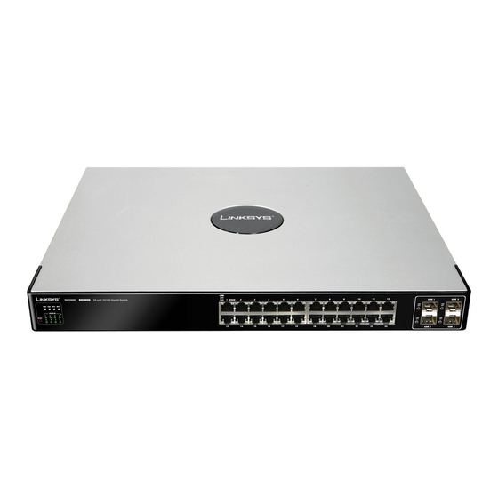
Getting to Know the Switch Overview The SGE2000 and SGE2000P models are 24-port, layer-2 Ethernet switches that expand the capability of the Linksys system. These two versions are functionally identical except the SGE2000P model offers Power-over-Ethernet (PoE) which can be used to supply power to various Linksys products over Ethernet cable. -
Page 9: Lan Port Leds
Linksys One Ready Communications Solution System Status LEDs A green PWR LED lights to indicate that the Ethernet switch is powered by internal power supplies. If the Ethernet switch is powered by a remote power supply (RPS), this LED blinks red. -
Page 10: Reset Switch
Reset Switch The Ethernet switch can be reset by inserting a pin or paper clip into the RESET opening. If the reset switch is held for 10 seconds or longer, the Ethernet switch will be reset to its default settings. -
Page 11: Uplink Ports
LC connectors, while the MGBT1 requires a Category 5e Ethernet cable with an RJ-45 connector. The Back Panel The power port is located on the back panel of the Ethernet switch. Power Port The 100-240 VAC power cord is connected to the Power port. -
Page 12: Console Port
An optional Redundant Power Supply (RPS) is connected to the RPS port. An RPS enhances the reliability of the Ethernet switch and it can keep the unit running if a power failure occurs. Only use a Linksys RPS1000 Redundant Power Supply unit and a proper RPS cable (RPSCBL1) with the Ethernet switch. -
Page 13: Chapter 3: Connecting The Switch
Before You Install the Switch... When you choose a location for the Ethernet switch, observe the following guidelines: • Make sure that the Ethernet switch will be accessible and that the cables can be easily connected. • Keep cabling away from sources of electrical noise, power lines, and fluorescent lighting fixtures. -
Page 14: Placement Options
Before connecting cables to the Ethernet switch, first you will physically install the Ethernet switch. Either set the Ethernet switch on its four rubber feet for desktop placement, mount it in a standard-sized, 19-inch wide for rack-mount placement, or mount it on a wall with the wall-mount brackets provided. -
Page 15: Wall-Mount Placement
Linksys One Ready Communications Solution 1. Remove the four front screws on one side of the Ethernet switch. Retain the screws for re- installation. 2. Place one of the supplied spacers on the side of the Ethernet switch so the four holes align to the screw holes. -
Page 16: Connecting The Cables
5. If you use the console interface to configure the Ethernet switch, then connect the supplied serial cable to the console port (located on the back of the Ethernet switch), and tighten the captive retaining screws. Connect the other end to your PC’s serial port. (The PC must be running VT100 terminal emulation software, such as HyperTerminal.) -
Page 17: Stacking Multiple Switches
Linksys One Ready Communications Solution If you will use the console interface to configure the Ethernet switch, proceed to ”Console Configuration” section on page 33 for directions. If you use the Web-based Utility to configure the Ethernet switch, proceed to ”Web Utility Configuration”... -
Page 18: Connecting Cabling For Stacking
By default, the Ethernet switch is in stacking mode. Using the console interface or the web interface, you can change the mode to standalone mode. -
Page 19: Managing Stacks
1. Reset all relevant units to by restoring them to the factory default mode. 2. Connect the units physically through the stacking ports, using standard Ethernet cables. 3. Assign each unit its desired number, making sure no duplicates exist, and reset the stack. Chapter 3: Connecting the Switch Managing Stacks... -
Page 20: Understanding Stack Resiliency
Unit IDs Each unit in a stack has an assigned unique Unit ID number. The following sections describe the Unit IDs and their characteristics. Linksys One Ready Communications Solution Chapter 3: Connecting the Switch Understanding Stack Resiliency... - Page 21 Stack Master. Only master-enabled units participate in the Master Election process and can become the Stack Master or Backup Master. (Units that are assigned a Unit ID of 3 through 8 can only Chapter 3: Connecting the Switch Understanding Advanced Stacking...
-
Page 22: Stack Unit Startup Process
1. The Master Discovery and Master Election processes. 2. Unit ID allocation by the Stack Master (including duplicate Unit ID conflict resolution). 3. Unit and port configuration by the Stack Master. Linksys One Ready Communications Solution Chapter 3: Connecting the Switch Understanding Advanced Stacking... - Page 23 Stack Master. If they have been running for the same amount of time, the unit with the Unit ID of 1 will be the Stack Master. If both Chapter 3: Connecting the Switch Understanding Advanced Stacking...
- Page 24 If the Stack Master is unable to allocate a Unit ID to a unit, that unit is effectively shut down and will not participate in the stack. For example, units with a conflicting Linksys One Ready Communications Solution Chapter 3: Connecting the Switch Understanding Advanced Stacking...
-
Page 25: Configuring Units And Ports
Stack Master and is copied to the Backup Master if one exists. You can use the command-line interface (CLI) or GUI to configure the stack units. Chapter 3: Connecting the Switch Configuring Units and Ports... -
Page 26: Setting The Unit's Operational Mode
If the Stack Master is reset, the entire stack is reset. To open the Stack Management Page: Click System > System Management > Stack Management. opens: The Stack Management Page Linksys One Ready Communications Solution Chapter 3: Connecting the Switch Configuring Units and Ports... - Page 27 Combo Ports — Indicates that the combo port is used as the stacking port. Copper Ports — Indicates that the copper port is used as the stacking port. Chapter 3: Connecting the Switch Configuring Units and Ports...
-
Page 28: Resetting The Unit To Factory Default Mode
Solid Green The switch is Unit ID n. ID n The switch is not Unit ID n or the switch is not stacked. All ports Solid The switch is powered on, but not operational. Linksys One Ready Communications Solution... -
Page 29: Stack Troubleshooting And Maintenance
If the incoming unit already has an assigned Unit ID, and that Unit ID is unused in the current stack, the incoming unit keeps its assigned Unit ID and the Stack Master applies any configuration relevant to that Unit ID to the incoming unit. Chapter 3: Connecting the Switch Stack Troubleshooting and Maintenance... - Page 30 If the units have uplink ports, then the first uplink port of the incoming unit is configured according to the configuration of the first uplink port of the failed unit. Linksys One Ready Communications Solution Chapter 3: Connecting the Switch Stack Troubleshooting and Maintenance...
-
Page 31: Replacing A Failed Stack Master Unit In An Operational Stack
Unit ID, the Stack Master cannot change it. If the incoming unit cannot be assigned an available Unit ID, then it is shut down and is not joined to the stack. Chapter 3: Connecting the Switch Stack Troubleshooting and Maintenance... -
Page 32: Splitting A Stack
The Stack Master notifies the system administrator of the removed units and ports that belong to the unreachable units by sending SYSLOG messages and SNMP traps. They are reported as “not present.” Linksys One Ready Communications Solution Chapter 3: Connecting the Switch Stack Troubleshooting and Maintenance... - Page 33 SNMP traps). • The partial stacks both continue to work as they did previously, but with fewer units. • No unit ID changes are performed in each of the partial stacks. Chapter 3: Connecting the Switch Stack Troubleshooting and Maintenance...
-
Page 34: Merging Two Stacks
To merge two working stacks and create one stack, first decide if you will merge the stacks while the incoming units are powered off during insertion, or if both stacks will be running when merged. Linksys One Ready Communications Solution Chapter 3: Connecting the Switch Stack Troubleshooting and Maintenance... - Page 35 When two stacks are combined, all of the configuration information for one of the stacks is lost. Only the surviving Stack Master (after the discovery and election processes are complete) maintains its configuration information. Chapter 3: Connecting the Switch Stack Troubleshooting and Maintenance...
-
Page 36: Understanding Stacking Cable Failure
All other units are shut down. NOTE: Occasionally, due to a race condition during the boot process, some of the units might be connected and join the stack. Linksys One Ready Communications Solution Chapter 3: Connecting the Switch Stack Troubleshooting and Maintenance... -
Page 37: Inserting A Standalone Unit Into A Running Stack
The ports that are connected to the other units’ stacking links will not pass any traffic, and the Stack Master will consider them as failed stacking links and route all traffic around them. Chapter 3: Connecting the Switch Stack Troubleshooting and Maintenance... -
Page 38: Chapter 4: Console Configuration
Console Configuration Overview The Ethernet switch features a menu-based console interface for basic configuration of the Ethernet switch and management of your network. The Ethernet switch can be configured using a menu-based interface through the console port or through a telnet connection. This chapter describes console interface configuration. - Page 39 Linksys One Ready Communications Solution 6. On the Connect To screen, select a port to communicate with the Ethernet switch. 7. Set the serial port settings as follows: • Bits per second: 115200 • Data bits: 8 • Parity: None •...
-
Page 40: Connecting To The Switch Using Telnet Or Ssh
Connecting to the Switch using Telnet or SSH If you know the IP address of your Ethernet switch (obtained from your DHCP server or the console interface), you can connect to the switch through a Telnet session. 1. Use your preferred Telnet or Secure Shell Client application, for example HyperTerminal or the Telnet application available through a Windows command window. -
Page 41: Switch Main Menu
Restore System Default Settings Reboot System Stack Configuration Back to main menu System Information Use this screen to check firmware versions and general system information for the Ethernet switch. Chapter 4: Console Configuration Configuring the Switch through the Console or Telnet Interface... - Page 42 Linksys One Ready Communications Solution Versions Use the Versions screen to display the boot, software, and hardware firmware versions of the Ethernet switch. In stacking mode, this information is displayed for the stack master. General System Information Use the General System Information screen to display the description, System Up Time, System MAC Address, System Contact, System Name, and System Location of the Ethernet switch.
- Page 43 Linksys One Ready Communications Solution Serial Port Configuration Use the Serial Port Configuration screen to display the baud rate of the Ethernet switch. To change the baud rate of the serial port: a. Select Edit to make changes. b. When your changes are complete, press the Esc key to return to the Action menu.
- Page 44 Select Edit to make changes. b. When your changes are complete, press the Esc key to return to the Action menu. c. Select Save to save your changes. Chapter 4: Console Configuration Configuring the Switch through the Console or Telnet Interface...
- Page 45 User & Password Settings The User & Password Settings screen lets you specify user names and passwords for the Ethernet switch. Up to 5 users can be assigned. NOTE: The default user is “admin” with no password. There is also a special user defined by default for internal use by the Linksys system (l1_admin).
- Page 46 Security Settings The Security Settings screen enables you to configure security settings on the Ethernet switch, as well as generate and display the certificate. Use the SSL Certificate Generation screen to specify a device-generated certificate. The following fields are specified:...
- Page 47 Type Y to verify that you want to disable the currently active management access profile. Chapter 4: Console Configuration Configuring the Switch through the Console or Telnet Interface Specifies the country name. (Range: 2 to 2) Specifies number of days certification is valid.
- Page 48 The IP Configuration screen displays these choices: the IP Address Settings, HTTP, HTTPS Configuration, and Network Configuration of the Ethernet switch. IP Address Configuration (Layer 2) The IP information of the Ethernet switch is displayed here. IP Address The IP Address of the Ethernet switch is displayed.
- Page 49 HTTPS server and configure the port on which the session is enabled. To change HTTPS settings: a. Select Edit to make changes. b. When your changes are complete, press the Esc key to return to the Action menu. Chapter 4: Console Configuration Configuring the Switch through the Console or Telnet Interface...
- Page 50 Select Edit to change the IP address, and select Execute to begin the traceroute test. After the traceroute test is complete, the TraceRoute screen displays the IP address, status, and statistics of the traceroute test. Chapter 4: Console Configuration Configuring the Switch through the Console or Telnet Interface...
- Page 51 Active Image The Active Image screen shows information about the active image file and the image file that will be active after reboot. Chapter 4: Console Configuration Configuring the Switch through the Console or Telnet Interface...
- Page 52 Select Reboot System and press the Enter key if you want to restart the Ethernet switch. You will be asked if you want to continue. Press the y key to reboot the Ethernet switch, or press the n key to cancel. After the Ethernet switch has rebooted, the Switch Main Menu screen will appear.
- Page 53 To view or edit the system mode: 1. On the Switch Main Menu screen, select System Mode (Layer 2 / Layer 3) Selection Port Configuration. 2. Press the Enter key. The System Mode (Layer 2 / Layer 3) Selection screen displays the current system and stacking mode.
- Page 54 4. Select Save to save your changes. 5. Reboot the Ethernet switch. Your new settings will take effect after reboot. Help The Help screen lets you view information about how to navigate the Ethernet switch menus. To view help information: 1. Select Help.
-
Page 55: Chapter 5: Web Utility Configuration
Console configuration or the Linksys One Administrator screen. If your Ethernet switch is part of a Linksys One system, the easiest way to manage it is with the Linksys One Portal — available only on the Linksys One Services Router. Refer to the Customer Premises Equipment Administration Guide for more details on the Linksys One Portal. -
Page 56: Appendix A: Linksys Contact Information
Linksys Contact Information Need to contact Linksys? Visit us online for information on the latest products and updates to your existing products at: http://www.linksys.com/international If you experience problems with any Linksys product, you can e-mail us at: In Europe E-mail Address Austria support.at@linksys.com Belgium... - Page 57 Linksys One Ready Communications Solution In Europe Russia Spain Sweden Switzerland United Kingdom Outside of Europe Asia Pacific Latin America Middle East & Africa South Africa U.S. and Canada Appendix A: Linksys Contact Information E-mail Address support.ru@linksys.com support.es@linksys.com support.se@linksys.com support.ch@linksys.com support.uk@linksys.com E-mail Address asiasupport@linksys.com (English only)
-
Page 58: Appendix B: Customer Site Survey
Customer Site Survey Use this Customer Site Survey to gather customer contact information and other information about the customer site that will be needed for the implementation and installation of the Linksys Solution. Customer Site Survey Site Name/Business Name Site Address Street Address City State... - Page 59 Linksys One Ready Communications Solution Customer Site Survey (Continued) Pager # E-mail After Hours Contact Phone Number Is this Site owned and maintained by the customer? Is this a manned site? Hours of Operation Number of Users Phone number and location of the telephone nearest to the Linksys equipment Access Procedures...
- Page 60 Specify any special security/safety procedures, such as the need for safety glasses, safety shoes, and the location(s) of hardhat areas. Security/Safety Procedures Specify the name and phone number of the site coordinator responsible for ensuring that the site is adequately prepared for the installation of the Cisco equipment. Site Coordinator Name: Phone:...
-
Page 61: Appendix C: Limited Warranty
Linksys One Ready Communications Solution Limited Warranty Linksys warrants this Linksys hardware product against defects in materials and workmanship under normal use for the Warranty Period, which begins on the date of purchase by the original end-user purchaser and lasts for the period specified for this product at www.linksys.com/warranty. -
Page 62: Obtaining Warranty Service
Linksys One Ready Communications Solution software or service offerings. This limited warranty does not guarantee any continued availability of a third party's service for which this product's use or operation may require. TO THE EXTENT NOT PROHIBITED BY LAW, ALL IMPLIED WARRANTIES AND CONDITIONS OF MERCHANTABILITY, SATISFACTORY QUALITY OR FITNESS FOR A PARTICULAR PURPOSE ARE LIMITED TO THE DURATION OF THE WARRANTY PERIOD. -
Page 63: Technical Support
Linksys One Ready Communications Solution Defective product covered by this limited warranty will be repaired or replaced and returned to you without charge. Customers outside of the United States of America and Canada are responsible for all shipping and handling charges, custom duties, VAT and other associated taxes and charges. -
Page 64: Appendix D: Federal Communication Commission Interference Statement
Federal Communication Commission Interference Statement This Equipment has been tested and found to comply with the limits for a Class A digital device, pursuant to part 15 of the FCC Rules. These limits are designed to provide reasonable protection against harmful interference when the equipment is operated in a commercial environment. -
Page 65: Appendix E: Specifications
Linksys One Ready Communications Solution Specifications Models • SGE2000 — 24-port 10/100/1000 Gigabit Ethernet Switch • SGE2000P — 24-port 10/100/1000 Gigabit Ethernet Switch with PoE Standards 802.3 10BASE-T Ethernet, 802.3u 100BASE-TX Fast Ethernet, 802.3ab 1000BASE-T Gigabit Ethernet, 802.3z Gigabit Ethernet, 802.3x Flow Control, 802.3ad LACP, 802.3af POE (SGE2000P only), 802.1d STP,... - Page 66 Layer 2 • MAC table size - 8K options • Number of VLANs - 256 active VLANs (4096 range) • VLAN - Port-based and 802.1Q Tag-based VLANs - Protocol-based VLAN, Management VLAN - Private VLAN Edge (PVE) - GARP VLAN Registration Protocol (GVRP) •...
- Page 67 Linksys One Ready Communications Solution Other • Traceroute Management • Single IP Management • Secure Socket Layer (SSL) security for Web UI • Secure Shell (SSH) • RADIUS • Port Mirroring • TFTP upgrade • DHCP Client • BootP • SNTP •...
- Page 68 DOS Attack prevention prevention Spanning IEEE 802.1D Spanning Tree, IEEE 802.1w Rapid Spanning Tree, IEEE Tree 802.1s Multiple Spanning Tree, Fast Linkover IGMP IGMP (v1/v2) snooping limits bandwidth-intensive video traffic to only Snooping the requestors. Support 256 multicast groups. Power Connection to RPSU for power redundancy Redundancy •...
- Page 69 Unit Weight • SGE2000 — 6.39 kg, 14.09 lbs • SGE2000P — 7.19 kg, 15.85 lbs Power • SGE2000 — 48 VDC (RPS), 100-240VAC, 50-60 Hz, 1.4A MAX • SGE2000P — 48 VDC (RPS), 100-240VAC, 50-60 Hz, 6.5A Appendix E: Specifications...
- Page 70 ©2007 Cisco Systems, Inc. All rights reserved. Linksys is a registered trademark and the Linksys One logo is a trademark of Cisco Systems, Inc. Release 1.0...