
Related Manuals for Honeywell PW7K1R1E


Summary of Contents for Honeywell PW7K1R1E
- Page 1 PW7K1R1E Input/Output Module Installation and Configuration Guide September 2020 © 2020 Honeywell. All rights reserved. 800-26498...
- Page 2 All other product and brand names are the service marks, trademarks, registered trademarks, or registered service marks of their respective owners. Printed in the United States of America. Honeywell Integrated Security reserves the right to change any information in this document at any time without prior notice.
-
Page 3: Table Of Contents
2.11 Input Circuit Wiring ................16 2.12 Relay Circuit Wiring ................17 2.13 Status LEDs..................18 2.14 IT Security................... 19 2.15 Specifications ..................20 2.16 Additional Mounting Information ............23 2.17 Warning ....................24 2.18 Liability ....................25 PW7K1R1E Configuration and Installation Guide, Document 800-26498... - Page 4 (This page is left blank intentionally for double-sided printing.) www.honeywell.com...
- Page 5 Introduction In this chapter... Overview Warranty Liability FCC Compliance PW7K1R1E Configuration and Installation Guide, Document 800-26498...
-
Page 6: Overview
The PW7K1R1E requires power from PoE or local 12VDC. The reader power should be based on peak reader power consumption. The PW7K1R1E may be mounted in a 3-gang switch box; a mounting plate is supplied with the unit. The PW7K1R1E may be mounted in an enclosure; the supplied mounting plate has mounting holes that match the MR50 mounting footprint. -
Page 7: Liability
This product is not intended for, nor is rated for operation in life-critical control applications. Honeywell Security Access is not liable under any circumstances for loss or damage caused by or partially caused by the misapplication or malfunction of the product. - Page 8 Introduction FCC Compliance (This page is left blank intentionally for double-sided printing.) www.honeywell.com...
- Page 9 PW7K1R1E Wiring and Setup In this chapter... PW7K1R1E Hardware Terminal Connections Jumper Configuration DIP Switch Configuration Input Power Communication Wiring OSDP Reader Wiring Input Circuit Wiring Relay Circuit Wiring Status LEDs Specifications Additional Mounting Information PW7K1R1E Configuration and Installation Guide, Document 800-26498...
-
Page 10: Pw7K1R1E Hardware
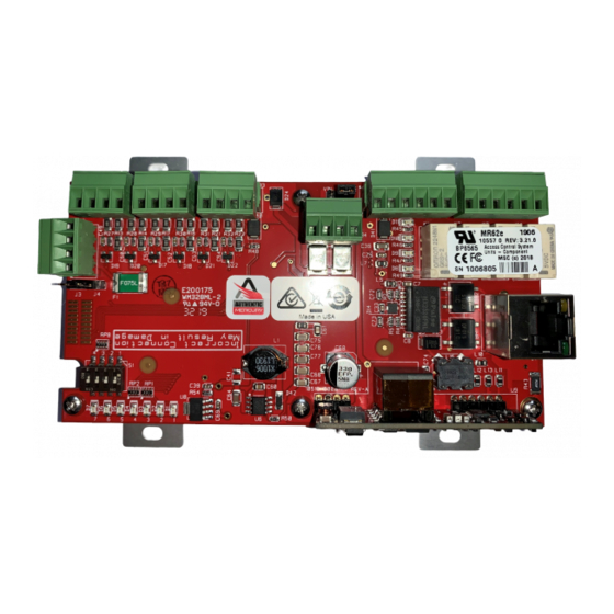
PW7K1R1E Wiring and Setup PW7K1R1E Hardware 2.1 PW7K1R1E Hardware Figure 2-1: PW7K1R1E Control Board www.honeywell.com... -
Page 11: Terminal Connections
PW7K1R1E Wiring and Setup Terminal Connections Figure 2-2: PW7K1R1E Control Board Solder Side STATUS LEDs RLY 2 RLY 1 NC C RELAY K2 (K2) RELAY K1 (K1) ETHERNET STATUS 1 2 3 4 5 6 LEDs 3.3V SOLDER SIDE 2.2 Terminal Connections... -
Page 12: Jumper Configuration
PW7K1R1E Wiring and Setup Jumper Configuration Table 1: PW7K1R1E Terminal Connections Terminal Acronym Description TB5-3 Relay K1-Normal Closed Contact TB5-4 Relay K2-Normally Open Contact TB5-5 Relay K2-Common Contact TB5-6 Relay K2-Normally Closed Contact TB6-1 Relay K3-Normally Open Contact TB6-2 Relay K3 – Common Contact TB6-3 Relay K3 –... -
Page 13: Dip Switch Configuration
See Bulk Erase below. Bulk Erase prompt mode at power up. See Bulk Erase section. All other switch settings are unassigned and reserved for future use. X = don’t care PW7K1R1E Configuration and Installation Guide, Document 800-26498... -
Page 14: Factory Default Communication Parameters
PW7K1R1E Wiring and Setup Factory Default Communication Parameters 2.5 Factory Default Communication Parameters Table 3: Factory Default Communication Parameters Network : static IP address: 192.168.0.251 Subnet Mask : 255.255.0.0 Default Gateway :192.168.0.1 2.6 Bulk Erase The bulk erase function can be used for the following purposes: •... -
Page 15: Input Power
When powering any remote device(s) by the MR62e, care must be taken not to Note: exceed the maximum current available. Cable gauge must also be evaluated. See specifications section for details. PW7K1R1E Configuration and Installation Guide, Document 800-26498... -
Page 16: Input Circuit Wiring
PW7K1R1E Wiring and Setup Input Circuit Wiring Figure 2-4: First Reader Port Wiring Figure 2-5: Second Reader Port Wiring BLK (6) BRN (4) ORG (5) WHT (3) CLK/D1 GRN (2) DAT/D0 RED (1) SECOND READER PORT DATA1/DATA0 OR CLOCK/DATA 2.11 Input Circuit Wiring Typically, these inputs are used to monitor door position, request to exit, or alarm contact. -
Page 17: Relay Circuit Wiring
For this reason, it is recommended that you should use either a diode or MOV (metal oxide varistor) to protect the relay. Wire should be of sufficient gauge to avoid voltage loss. PW7K1R1E Configuration and Installation Guide, Document 800-26498... -
Page 18: Status Leds
PW7K1R1E Wiring and Setup Status LEDs Figure 2-7: Relay Circuit Wiring Diagram Diode Selection: • Diode current rating: 1x strike count • Diode breakdown voltage: 4x strike voltage • For 12VDC or 24VDC strike, diode 1N4002 (100V/1A) typical MOV Selection: •... -
Page 19: Security
Note: state for 0.1 second, otherwise, the LED is off After the PW7K1R1E has received its IP address, the following table describes the LEDs in the normal running mode. If the communication is lost, the PW7K1R1E reverts back to the “waiting for IP address” mode: DESCRIPTION On-line, encryption disabled = 0.8 second ON, 0.2 second OFF... -
Page 20: Specifications
PW7K1R1E Wiring and Setup Specifications 2.15 Specifications The interface must be used in low voltage, class 2 circuits only. The installation of this device must comply with all local fire and electrical codes. Power Input • PoE Power Input 12.95W, compliant to IEEE 802.3af - OR - •... - Page 21 • 500-foot (150 m) maximum Reader data (RS- • 24AWG 485) • 120-ohm impedance • Twisted pair with shield • 4000-foot (1,219 m) maximum Environmental Temperature • -55°C to +85°C, storage • 0°C to +70°C, operational PW7K1R1E Configuration and Installation Guide, Document 800-26498...
- Page 22 PW7K1R1E Wiring and Setup Specifications Humidity • 5 to 95% RHNC Mechanical Dimension • 5.5" (140mm) W x 2.75" (70mm) L x 0.96" (24mm) H without bracket • 5.5" (140mm) W x 3.63" (92mm) L x 1.33" (34mm) H with bracket Weight •...
-
Page 23: Additional Mounting Information
Available from Graybar, part number 88158404. • Magnetic switch set: G.R.I. part number: 505. Figure 2-8: Stainless Steel Blank Cover OPTIONAL BLANK COVER W/SCREWS PW-6K1R1E WITH INCLUDED MOUNTING PLATE OPTIONAL 3-GANG JUNCTION BOX TO ETHERNET FIELD WIRING NETWORK PW7K1R1E Configuration and Installation Guide, Document 800-26498... -
Page 24: Warning
PW7K1R1E Wiring and Setup Warning Figure 2-9: Mounting Plate Dimensions Ø0.16 [Ø4.0] Ø0.16 [Ø4.0] 3-GANG MGT HOLES MR50 MGT HOLES 2.35 [59.7] 3.30 [83.8] 3.63 [92.1] 3.63 [92.1] 3.85 [97.8] 5.50 [139.7] 2.17 Warning Mercury Security warrants the product is free from defects in material and workmanship under normal use and service with proper maintenance for one year from the date of factory shipment. -
Page 25: Liability
Mercury Security is not liable under any circumstances for loss or damage caused by or partially caused by the misapplication or malfunction of the product. Mercury Security’s liability does not extend beyond the purchase price of the product. PW7K1R1E Configuration and Installation Guide, Document 800-26498... - Page 26 PW7K1R1E Wiring and Setup Liability (This page is left blank intentionally for double-sided printing.) www.honeywell.com...
- Page 27 (This page is left blank intentionally for double-sided printing.)
- Page 28 For more information: www.honeywellintegrated.com Honeywell Integrated Security 135 W. Forest Hill Avenue Oak Creek, WI 53154 414-766-1700 414-766-1798 Fax European Office Boblingerstrasse 17 Specifications subject to change D-71101 Schonaich without notice. Germany 49-7031-637-782 © Honeywell. All rights reserved. 49-7031-637-769 Fax 800-26498 www.honeywell.com...