Table of Contents
Advertisement
Quick Links
Advertisement
Table of Contents

Related Manuals for Unic AURA 2


Summary of Contents for Unic AURA 2
- Page 1 AURA User manual * AU9920- 2020.06 *Original instructions...
- Page 2 Installation diagram AURA 2 890 min 50 min CW I...
- Page 3 installation diagram AURA 3 50min 1080 min 50 min CW I...
- Page 4 DO = Drain outlet EQ = Equipotential screw EI = Electricity inlet CWI = Cold water inlet G 3/8″...
- Page 5 Foreword The installation, use and maintenance manual (hereinafter Manual) provides the user with information necessary for correct and safe use of the machine (or “appliance“). The following must not be considered a long and exacting list of warnings, but rather a set of instructions suitable for improving machine performance in every respect and, above all, preventing injury to persons and animals and damage to property due to im- proper operating procedures.
-
Page 6: Table Of Contents
Contents A SAFETY INFORMATION ......................... 7 General information ........................7 General safety ..........................7 Personal protection equipment ......................8 Transport, handling and storage ...................... 8 Installation and assembly ....................... 9 Water connection.......................... 9 Electrical connection ........................9 Use ............................10 appliance cleaning and maintenance .................... -
Page 7: Asafety Information
SAFETY INFORMATION General information To ensure safe use of the appliance and a proper understanding of the manual it is necessary to be familiar with the terms and typographical conventions used in the documentation. The following symbols are used in the manual to indicate and identify the various types of hazards: WARNING Danger for the health and safety of operators. -
Page 8: Personal Protection Equipment
Personal protection equipment Summary table of the Personal Protection Equipment (PPE) to be used during the various stages of the machine's service life. Stage Protective Safety Gloves Glasses Safety garments footwear helmet — ● ○ — ○ Transport — ● ○... -
Page 9: Installation And Assembly
Installation and assembly • The installation must be carried out by a specialised personnel. • Follow the installation instruction supplied with the appliance. • Do not install a damaged appliance. Any missing or faulty parts must be replaced with original parts. •... -
Page 10: Use
isolation fault in the TN or TT systems or, for IT systems, the use of isolation controllers or differential current protection devices to activate automatic power disconnection (an isolation controller must be provided for indicating a possible first earth fault of a live part, unless a protection device is supplied for switching off the power in case of a such a fault. -
Page 11: Machine Disposal
A.12 Machine disposal • Work on the electrical equipment must only be carried out by a specialised personnel, with the power supply disconnected. • Dismantling operations must be carried out by specialised personnel. • Make the appliance unusable by removing the power cable and any compartment closing devices, to prevent the possibility of someone becoming trapped inside. -
Page 12: Appliance With 3 Positions Main Switch
C.4.1 Appliance with 3 positions main switch • tampering with the guards or safety devices; • failure to use personal protection equipment by operators, • 0 = appliance OFF specialised personnel and maintenance personnel; • 1 = power turn ON and filling boiler(s) •... -
Page 13: Dgeneral Information
IMPORTANT Residual risk Description of hazardous In case of a significant anomaly (e.g. short circuits, situation wires coming out of the terminal block, motor Crushing or injury The specialised personnel may breakdowns, worn electrical cable sheathing, etc.) not correctly fix the control panel the operator must immediately deactivate the when accessing the technical machine. -
Page 14: Additional Indications
The data plate is located on the front of the equipment. the spare parts catalogue (the fitting and use of non-original spare parts and accessories can negatively affect machine operation and invalidates the original manufacturer warranty); • operations carried out by non-specialised personnel; •... -
Page 15: Ftechnical Characteristics
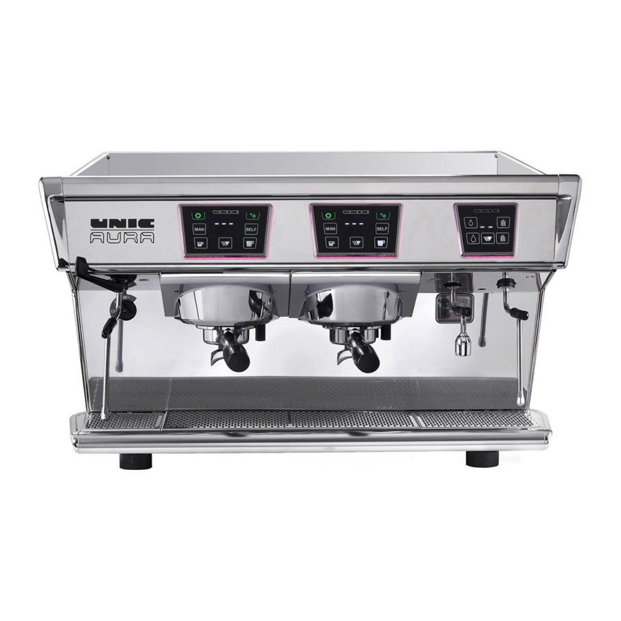
TECHNICAL CHARACTERISTICS Data table MODELE AURA 2 AURA 3 Width 790 mm [31″] 980 mm [38.5″] Height 480 mm [19″] 480 mm [19″] Depth 600 mm [23.6″] 600 mm [23.6″] Weight 70 kg [154.3 Lbs]... -
Page 16: Dosamat Box
G.2.2 Dosamat box 7. Touch 8. Disabled touch G.4.1 Access to parameter Double authentication to enter in setting : • Step 1: press 3 seconds on programming icon • Step 2: press simultaneously during 3 seconds on cleaning SELF and continu/stop icons to enter in settings. -
Page 17: Launching Of Cleaning After Group Blocked
H.1.2 Launching of cleaning after group blocked Rinsing the cup seal: • Engage the filter—holder on the unit without tightening it. • Press the cleaning icon (it turns blinking blue). • Press a coffee touch by tightening and loosening the filter— •... -
Page 18: Use
3. Level 3 Medium foam 1. Hot water icon (small dose) 4. Steam only 2. Display 3. Steam icon 4. Steamair icon 5. Continu/stop icon J.3.1 Automatic mode (To reach the programmed T℃ ℃ ) 6. Hot water icon (large dose) One impulse on the touch makes the Steamair flow until the liquid reaches the preset temperature. - Page 20 Electrolux Professional SPA Viale Treviso 15 33170 Pordenone www.electroluxprofessional.com...