Table of Contents
Advertisement
Advertisement
Table of Contents

Related Manuals for HP OMEN 27i


Summary of Contents for HP OMEN 27i
- Page 1 Maintenance and Service Guide OMEN 27i model...
- Page 2 SUMMARY This guide provides information about spare parts, removal and replacement of parts, diagnostic tests, problem troubleshooting, and more.
- Page 3 Before Devices, Inc. Bluetooth is a trademark performing any maintenance or service, be owned by its proprietor and used by HP sure to read “Important Safety Information”. Inc. under license. NVIDIA is a trademark and/or registered trademark of NVIDIA Corporation in the U.S.
-
Page 5: Table Of Contents
Table of Contents 1. Getting started .............................. 1 Important safety information ........................1 Important service information and precautions ..................1 RoHS (2002/95/EC) requirements ......................2 General descriptions ..........................2 Firmware updates ............................ 3 Before returning the repaired product to the customer ................3 2. -
Page 7: Getting Started
1. Getting started Read this chapter to learn about safety information and where to find additional HP resources. Important safety information Carefully read the cautions and notes within this document to minimize the risk of personal injury to service personnel. The cautions and notes are not exhaustive. Proper service methods are important to the safe, reliable operation of equipment. -
Page 8: Rohs (2002/95/Ec) Requirements
Please note during servicing that the primary side is the high voltage area. ● This monitor meets ROHS requirements. Be sure to use lead-free solder wire when soldering. ● If you must change a capacitor, be sure to match the polarity as printed on the PCB. ●... -
Page 9: Firmware Updates
Level 2: Circuit board or standard parts replacement Firmware updates Firmware updates for the monitor are available at support.hp.com. If no firmware is posted, the monitor does not need a firmware update. Before returning the repaired product to the customer Perform an AC leakage current check on exposed metallic parts to be sure the product is safe to operate without the potential of electrical shock. -
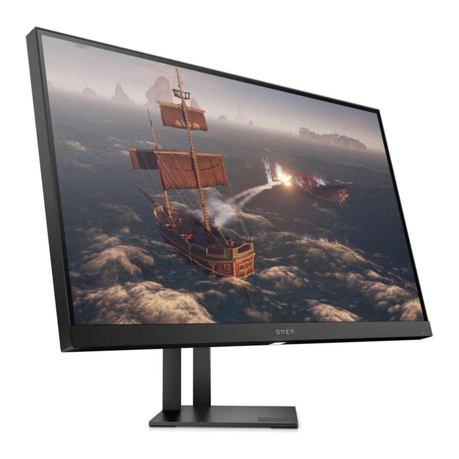
Page 10: Monitor Features
For safety and regulatory information, refer to the Product Notices provided in your documentation kit. To access the latest user guides or manuals for your product, go to http://www.hp.com/support and follow the instructions to find your product. Then select Manuals. -
Page 11: Front Components
Front components To identify the components on the front of the monitor, use this illustration and table. Press the power button on the rear of the monitor to turn it on. -
Page 12: Rear Components
Rear components To identify the components on the rear of the monitor, use this illustration and table. Table 1-1: Rear components and their descriptions Component Function OSD joystick Opens the OSD menu, selects an item from the menu. or closes the OSD menu. Power button Turns the monitor on or off. - Page 13 device such as a computer or game console.
-
Page 14: Locating The Serial Number And Product Number
Depending on the product, the serial number and product number are located on a label on the rear of the monitor or on a label under the front bezel of the monitor head. You might need these numbers when contacting HP about the monitor. For worldwide models (except India):... -
Page 15: Illustrated Parts Catalog
DECO PLASTIC POWER LED LENS PANEL MIDDLE FRAME POWER LED BOARD HINGE BKT IO ESD FINGER USB ESD FINGER AMB BTM LED BOARD FUNCTION KEY BOARD FUNCTION KEY POWER KEY REAR COVER HP LOGO AMB BTM LED LENS BTM REFELCTOR... -
Page 16: How To Order Parts
SCREW M3 L4 SCREW M3 L5 SCREW Q3 L6 SCREW M4 L10 SCREW M4 L8 How to order parts The HP authorized repair center can purchase the adaptor from HP. Power board Description HP spare part number Manufacturer part number L39754-003... - Page 17 You can purchase cables from the HP part store at https://partsurfer.hp.com/Search.aspx. NOTE: HP continually improves and changes product parts. For complete and current information about supported parts for your computer, go to http://partsurfer.com, select your country or region, and then follow the on-screen instructions.
-
Page 18: Removal And Replacement Procedures
4. Removal and replacement procedures Adherence to these procedures and precautions is essential for proper service. Preparation for disassembly Use this information to properly prepare to disassemble and reassemble the monitor. 1) Read the “Important safety information” and “Important service information and precautions” sections in the “Getting started”... - Page 19 Before removing the RC, follow these steps: Prepare the monitor for disassembly. See Preparation for disassembly on page 12. ▲ Remove the RC: Step Figure Description Unplug the cable by hand. Remove the screws by the Remove the Screwdriver HINGE ASS'Y first and then remove the hinge assy...
- Page 20 Remove the Remove the BACK_COVER screws by the Screwdriver first, and then remove the Remove the BACK COVER mainframe by the Scraper disconnect connectors by hand and use screw driver remove the other boards.
- Page 21 mainboard Remover the rear cover by the scraper Remove the rear Tear out all cover and bezel tapes and deco disconnect connectors by Remove the middle hand and use frame to separate screw driver mainframe and to remove the panel middle frame to separate mainframe...
-
Page 22: Connector Repair
panel Connector repair This procedure includes HDMI, Display Port , USB and phone JACK connectors. The connectors are on the main board (board part number CBPCNBAHPF2). The connectors identifiers are as follows: Connector Location HDMI Display Port PHONE JACK DC JACK TYPE A TYPE A TYPE B... - Page 23 Before repairing connectors, follow these steps: Prepare the monitor for disassembly. See Preparation for disassembly on page 12. ▲ IMPORTANT: • Repair Condition: Connector repair is only for out of warranty. • Repairing must operate by professional repairers (Note) in repair center, not applicable for end user. •...
-
Page 24: Phone Jack M1
• After repaired, must connect source to each port to check Main board function is ordinary. Note: (The requirement of professional repairers’ regulation by ERP lot5) 1) The professional repairer has the technical competence to repair electronic displays and complies with the applicable regulations for repairers of electrical equipment in the Member States where it operates. -
Page 25: Hdmi Connector J2
through holes. 2) Lift the M2 connector from the PCB. 3) Place the new component on the PCB. Be sure that it matches the PCB footprint. 4) Solder the new component. HDMI connector J2 Repair the HDMI connector: 1) Use a soldering iron and a desoldering pump to remove as much solder as possible from the pin. 2) Use a hot air gun to melt the solder on the pins. -
Page 26: Dp Connector J3
3) Lift the J2 connector from the PCB. 4) Place the new component on the PCB. Be sure that it matches the PCB footprint. 5) Solder the new component. DP connector J3 Repair the DP connector: 1) Use a soldering iron and a desoldering pump to remove as much solder as possible from the pin. 2) Use a hot air gun to melt the solder on the pins. -
Page 27: Type A J4,J5
4) Place the new component on the PCB. Be sure that it matches the PCB footprint. 5) Solder the new component. TYPE A J4,J5 Repair the TYPE A connector: 6) Use a soldering iron and a desoldering pump to remove as much solder as possible from the pin. 7) Use a hot air gun to melt the solder on the pins. -
Page 28: Function Test
Lift the J6 connector from the PCB. 3) Place the new component on the PCB. Be sure that it matches the PCB footprint. 4) Solder the new component. Function test After repair, be sure to confirm that all functions are working. Table 4-1: Function test Test item... - Page 29 Table 4-2: Solving common problems Problem Possible cause Solution Screen is blank Power cord is disconnected. Connect the power cord. or video is flashing. Monitor is off. Power the power button. NOTE: If pressing the Power button has no effect, press and hold the power button for 10 seconds to disable the Power button lockout...
- Page 30 displayed on screen. The monitor is The monitor’s power saving control is disabled. Open the OSD menu and off, but it did not select Power Control > seem to enter Auto-Sleep Mode and set into Sleep auto-sleep to On. mode. On-Screen The monitor’s OSD lock function is enabled.