
Related Manuals for Motorola OM 2000

Summary of Contents for Motorola OM 2000
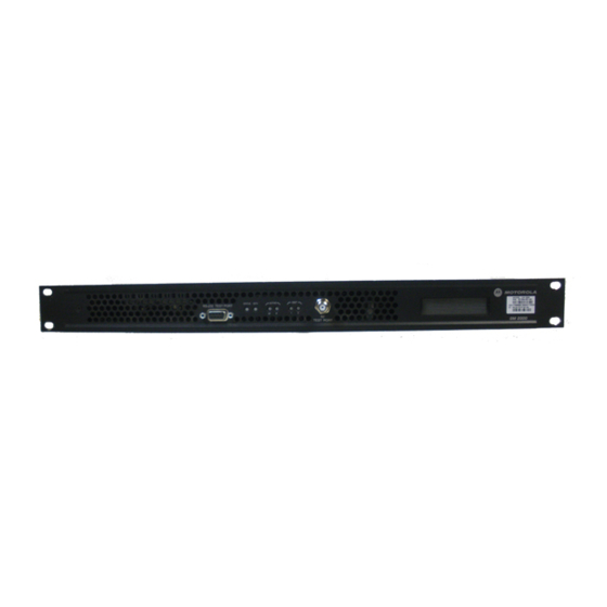
- Page 1 I N S TA LLAT I ON & OPE RA T ION M A N UA L OM 2000 Out of Band Modulator, Software Version 1.0.x Replaces: 539808-001-c...
- Page 3 CAUTION These servicing and installation instructions are for use by qualified personnel only. To reduce the risk of electrical shock, do not perform any servicing other than that contained in the Installation and Troubleshooting Instructions unless you are qualified to do so. Refer all servicing to qualified service personnel.
- Page 4 Operation of this equipment in a residential area is likely to cause harmful interference in which case the user will be required to correct the interference at his/her own expense. Any changes or modifications not expressly approved by Motorola could void the user’s authority to operate this equipment under the rules and regulations of the FCC.
- Page 5 Motorola Customer Service for assistance. © 2009 Motorola, Inc. All rights reserved. No part of this publication may be reproduced in any form or by any means or used to make any derivative work (such as translation, transformation, or adaptation) without written permission from Motorola, Inc.
-
Page 7: Table Of Contents
Connecting Ethernet and Modulator Output Cables .............19 Connecting Optional Serial Port Cables ..................20 Connecting the Optional Ground .....................20 Connecting Emergency Alert Wiring....................20 OM 2000 Power Connection to AC Power..................21 OM 2000 Power Connection to DC Power..................21 Confirming Correct Installation......................22 4 Setup and Operation ..........................23 Network Connection..........................23... - Page 8 CONTENTS About............................32 Exit ..............................33 Configuration............................33 Physical Interface Configuration..................... 34 Logical Ports Configuration ...................... 35 Network Configuration ......................38 Status ............................39 Status—Alarms .......................... 40 OM Identification........................42 Status — Save Entire OM Status .................... 43 5 Troubleshooting............................45 Testing the RF Modulator .........................
- Page 9 Figure 1-1 — OM 2000 Out-of-band Modulator ..................1 Figure 2-1 — OM 2000 operational flow diagram.................7 Figure 2-2 — OOB data flow through the OM 2000 ................9 Figure 2-3 — Creating an output multiplex....................11 Figure 2-4 — RF modulator block diagram ....................12 Figure 2-5 —...
- Page 10 Table 2-1 — OM 2000 input ports ......................9 Table 2-2 — Multiplexer output destinations ..................10 Table 2-3 — OM 2000 front panel RF monitor jack and indicators............ 14 Table 2-4 — OM 2000 input/output and power connections.............. 15 Table 4-1 —...
-
Page 11: Introduction
1 INTRODUCTION The Motorola OM 2000 Out-of-band Modulator links the digital headend equipment with the distribution system by combining the various out-of-band inputs into a quadrature phase shift key (QPSK)-modulated signal. It converts multiple digital input streams into an RF output signal for transmission over the cable system. -
Page 12: Using This Manual
Related Documentation The System Release Notes provide information that can be used with the OM 2000. Although these documents provide information that may be of interest, they are not required to install or operate the OM 2000: •... -
Page 13: Document Conventions
1 INTRODUCTION Document Conventions Before you begin, familiarize yourself with the stylistic conventions used in this document: Bold type Indicates text you must type exactly as it appears, or a default value Denotes a displayed variable or a variable that you Italic type must fill in Condensed type... -
Page 14: Getting Help
• Motorola Online: http://businessonline.motorola.com The TRC is on call 24 hours a day, 7 days a week. In addition, Motorola Online offers a searchable solutions database, technical documentation, and low-priority issue creation and tracking. For specific toll-free numbers when calling from outside the... -
Page 15: Returning For Repair
1 INTRODUCTION Returning for Repair If repair is necessary, call the Motorola Repair Facility at 800 642 0442 for a Return for Service Authorization (RSA) number before sending the unit. When calling from outside the United States, use the appropriate international access code then 52 631 311 1100 to contact the Repair Facility. -
Page 17: Overview
Other devices in the headend create the specific commands, messages, and downloadable code that make up the information contained in the OOB datastream. The OM 2000 accepts this information and processes it for delivery on the OOB channel by combining it into an MPEG-2-compliant transport multiplex and outputting that transport multiplex as an RF signal. -
Page 18: Functional Overview
OOB data transmission. OOB Signal Processing In converting the OOB data inputs into an RF signal, the OM 2000 performs the following OOB signal processing functions: • Receives the cable terminal control stream and other OOB data from multiple input sources •... - Page 19 Figure 2-2 — OOB data flow through the OM 2000 Receiving OOB Data Inputs The OM 2000 can receive OOB data through multiple input ports. All data ports are located on the back panel, and each has a unique numeric identifier. Table 2-1 describes the OM 2000 input ports: Table 2-1 —...
- Page 20 2 OVERVIEW In general, OOB data input to the OM 2000 must be in MPEG-2 transport packets. Data sent to configure, control, and boot the OM 2000 need not conform to MPEG-2 format. Multiplexing the OOB Data The packet multiplexer combines OOB data from the Ethernet and serial input ports into a single MPEG-2-compliant transport multiplex, and then routes this multiplex to the RF modulator.
- Page 21 Depending on your system configuration, the cable-terminal control-stream input to the OM 2000 can include the PID 0 and PID 1 control streams required to define the OOB transport multiplex. If not, these streams are added to the multiplex before it is input to the RF modulator.
- Page 22 2 OVERVIEW PID 0 and PID 1 packets, as well as commands specifying how often the generator should insert the packets into the multiplexer. Generating the RF Output The RF modulator receives the OOB data transport multiplex created by the packet multiplexer and performs the following functions to convert it for RF transmission: Forward error correction An FEC encoder performs Reed/Solomon encoding, data...
-
Page 23: Physical Overview
Indicators and Connectors The OM 2000 indicators, as well as the RF monitor jack, are located on the front panel. Figure 2-6 illustrates the front-panel indicators: Figure 2-6 — OM 2000 front panel... - Page 24 2 OVERVIEW Table 2-3 summarizes the function of the RF monitor jack and each indicator: Table 2-3 — OM 2000 front panel RF monitor jack and indicators Connector/Indicator Description Nine-pin RS-232 Test Port (behind front bezel) — an interface RS-232 Test Port used to access internal diagnostics from the operating system command line shell.
-
Page 25: Input/Output And Power Connections
–20 dB test RF monitor jack is an F-type connector that permits convenient monitoring of the RF output at the front panel. The OM 2000 display shows the IP address and RF frequency configured on the device. Input/Output and Power Connections... - Page 26 2 OVERVIEW Connector Description The RF Modulator port provides RF output in a frequency range from 71 to 129 MHz in 50 KHz steps. The OOB data carried in the RF signal is transmitted at 2.005 Mbps QPSK and are null filled between data packets.
-
Page 27: Installation
7 feet 6 inches, 18AWG • DC cord, 3 conductor, 15 feet, 14 AWG 2. The following items that are not included with the OM 2000, but are necessary to complete the installation: Item Description (rear panel connections) Ethernet cable with RJ-45 connectors For connection to OAM&P system interface... -
Page 28: Mounting The Om 2000
Appendix B, “Cabling Specifications," for the length restrictions, connector, and cable or wire type for each connection required for your system. Note: RS530 serial cables for use with the OM 2000 can be purchased from Motorola. The RS530 cable part numbers are: •... -
Page 29: Connecting The Interface Cables
Caution! To avoid possible damage to the OM 2000, ensure that the ac-power cord is disconnected before connecting any I/O cables. Connecting Ethernet and Modulator Output Cables For most applications, the RF modulator must be connected to the distribution system. -
Page 30: Connecting Optional Serial Port Cables
7. Repeat steps 4 through 6 for the female connector marked opt2. Connecting the Optional Ground Connect a ground wire from the OM 2000 to the rack frame using a #10-32 screw. Connecting Emergency Alert Wiring The OM 2000 emergency alert function may not operate reliably if an excessive voltage differential exists between the remote control unit chassis and the OM 2000 chassis. -
Page 31: Om 2000 Power Connection To Ac Power
–40 through –60 V Caution! The OM 2000 with DC power must be installed in a restricted access area. Do not power this device with less than -40 V DC... -
Page 32: Confirming Correct Installation
4 – Switching or disconnecting devices shall not be in the earthed circuit conductor between the dc source and the point of connection of the earthing electrode conductor. Confirming Correct Installation After applying power to the OM 2000, there is short initialization period. If the installation is correct: • The green indicator is on. -
Page 33: Setup And Operation
4 SETUP AND OPERATION At power-up, the OM 2000 operating parameters are set either by data stored internally in non-volatile storage (FLASH) or by data downloaded from a Bootstrap Protocol (BOOTP) server on the headend LAN. The method used depends on your system configuration. -
Page 34: Browsers
4 SETUP AND OPERATION Browsers Recommended web browsers to run the OM-EM are reasonably current versions of ® ® Netscape Navigator (latest version is 7 .1) or Microsoft Internet Explorer (latest version is 7 .0). Browser or proxy settings are not required. The latest versions of these browsers can be downloaded from the following web sites: •... - Page 35 4 SETUP AND OPERATION Figure 4-1 — Initiating an OM-EM Session 2. As applicable: • Click the hyperlink to download the JRE 1.2.2 from the Sun website (if no connection occurs, you will have to visit the Sun website and search for JRE downloads).
- Page 36 4 SETUP AND OPERATION The OM Element Manager Login window is displayed in Figure 4-3 (a typical IP address is shown): Figure 4-3 — OM Element Manager Login window 5. Type a (root is the default). <User name> 6. Type a (password is the default).
- Page 37 4 SETUP AND OPERATION Figure 4-5 — OM 2000 Alarms window If the OM does not have an active OM Unit Alarm, the OM-EM Main window is displayed (as shown in Figure 4-6). The drop-down lists for each of the menu bar...
-
Page 38: Om-Em Software Toolset
The OM-EM is the primary interface to the OM for setup and operation. It is a remote user interface based on a Java application that enables you to monitor an OM 2000 remotely and locally. The software toolset has four drop-down lists that enable access to screen-sets, as follows: •... -
Page 39: System
4 SETUP AND OPERATION Button Function State Refresh Loads (reads) values for all fields Always enabled from the OM. All changes not applied are lost. If you change a field and do not apply it, clicking refresh restores the original value. -
Page 40: Reboot
Display current OM revision level information • Exit the OM-EM These activities are described in the following subsections. Reboot The OM 2000 Reboot pop-up is illustrated in Figure 4-9. Figure 4-9 — OM 2000 Reboot pop-up Click Yes to reboot the OM 2000. -
Page 41: Administration
4 SETUP AND OPERATION Administration The Administration window is only accessible while logged in as “root. ” The default user name is root, and the default password is password. The Administration window is illustrated in Figure 4-10 and defined in Table 4-3. Figure 4-10 —... -
Page 42: Setting The Password
4 SETUP AND OPERATION Setting the Password The Setting menu item is only accessible while logged in as a user other than “root. ” This opens the Set Password Window. It allows the current user’s password to be changed. Consistent with standard software procedures, changing requires entering the current user name or password followed by the new one. -
Page 43: Exit
Click Yes to exit or click No to remove the popup. Configuration Clicking Configuration on the OM-EM menu bar displays the drop-down list, as illustrated in Figure 4-14. Figure 4-14 — Configuration drop-down list The OM 2000 Configuration screen-sets described below include: • Physical Interface Configuration • Logical Ports Configuration •... -
Page 44: Physical Interface Configuration
Figure 4-15 — OM 2000 Physical Interface Configuration window The Physical Interface Configuration screen shows the physical interface type options available on the OM 2000. (Note that Types 4 and 8 on the screen are not used.) These type options are: 1. -
Page 45: Logical Ports Configuration
10. PID Generator — MPEG Message Generator port option. 11. Not used. Logical Ports Configuration The OM 2000 supports up to 16 logical ports, designated ports 1 through 16. At least one logical port must be an input and at least one logical port must be an output. - Page 46 4 SETUP AND OPERATION Figure 4-16 — OM 2000 Logical Ports Configuration window Table 4-4 — System Time window field definitions Item Definition Logical Port Index A number between 1 and 16 Physical Interface Which physical interface is assigned to the logical port Operation Mode Input —...
- Page 47 4 SETUP AND OPERATION PID Table Configuration Each logical input port has an associated PID Table. The first row of the PID Table is used to route the logical input to up to three logical outputs. The second through 28th rows are used to drop PIDs, route PIDs to other logical output ports, and to re- map PIDs to other values.
-
Page 48: Network Configuration
4 SETUP AND OPERATION Network Configuration The Ethernet window provides the ability to identify the host default gateway. It provides the ability to view the MAC address of ENET1, as well as the ability to define the IP Address and Subnet Mask (if applicable) for this Ethernet port. The Ethernet window is illustrated in Figure 4-18 and defined in Table 4-5. -
Page 49: Status
4 SETUP AND OPERATION Table 4-5 — Ethernet window field definitions Item Definition IP Address Used to give the OM-2000 a new IP address Subnet Mask Used to give the OM-2000 a new subnet mask Host Name Contains the name of the DAC listed in the OM-2000’s Host file. Can contain NOHOST if no DAC is present. -
Page 50: Status-Alarms
4 SETUP AND OPERATION Refer to the applicable subsection for those Status windows that were invoked from button selections of other windows. The subsections that follow describe Status windows that are selected solely from the menu drop-down list. Table 4-6 — OM Element Manager Status Drop-down List Definitions Status OM Alarms Window of all OM Alarms... - Page 51 This is an error condition. Invalid Multicast TTL Displays the number of invalid multicast TTL values found in the configuration. This is an error condition. OM 2000 Unit Alarms This matches the highest alarm level in all OM 2000 alarms.
-
Page 52: Om Identification
4 SETUP AND OPERATION OM Identification This window represents a software panel of monitored events in the OM 2000. The Status — Events window is illustrated in Figure 4-21 and defined in Table 4-8. Figure 4-21 — Events window Table 4-8 — Events window field definitions... -
Page 53: Status - Save Entire Om Status
4 SETUP AND OPERATION Status MIB Version Displays the MIB version used in the Application Code Area User configurable Rack User configurable Shelf User configurable Status — Save Entire OM Status The Save Entire OM Status interface saves all of the status to a status.txt file, which is located in the same directory as the omem.jar file. -
Page 55: Troubleshooting
Motorola Online: http://businessonline.motorola.com The TRC is on call 24 hours a day, 7 days a week. In addition, Motorola Online offers a searchable solutions database, technical documentation, and low-priority issue creation and tracking. For specific toll-free numbers when calling from outside the United States, please refer to your product manual or our Web page. - Page 56 5 TROUBLESHOOTING Table 5-2 — Common fault indications Problem Possible Cause Corrective Action OM 2000 powers up but fails BOOTP/TFTP configuration Check the BOOTP configuration to initialize and all the file paths and names on the server. Mechanical error with unit Repair or replace the unit.
-
Page 57: Testing The Rf Modulator
5 TROUBLESHOOTING Testing the RF Modulator Although these test modes are mainly intended for factory testing, they can be useful in isolating specific faults. Table 5-3 summarizes the modulator port test modes. Note: The mode of the RF modulator can be changed on the Physical Interface Configuration screen (Figure 4-15) in the Element Manager. -
Page 59: Appendix A - Specifications
APPENDIX A — SPECIFICATIONS RF Output Modulation DQPSK Carrier symbol rate 1.024 Msps Carrier suppression 50 dB typical Center frequency 71 through 129 MHz (configurable) Frequency step size 50 kHz +30 to +50 dBmV (configurable) Level Level step size 0.5 dB Spurious outputs -60 dBc minimum IF Output... -
Page 60: Operating Environment
APPENDIX A — SPECIFICATIONS Operating Environment 32 °F to 122 °F (0 °C to 50 °C ) Ambient temperature Ambient humidity 0 through 90%, non-condensing –40 °F to 158 °F (–40 °C to 70 °C ) Storage temperature Cooling 2 Fans Physical Specifications Dimensions 1.75 H X 19 W X 18 D inches... -
Page 61: Interconnection Specifications
APPENDIX A — SPECIFICATIONS Interconnection Specifications Ethernet port Network data rate ~100 Mbps maximum OM 2000 data rate 2.005 Mbps output maximum Interface IEEE 802.3 Impedance 120 ohms Cable Shielded twisted pair Connector RJ-45 (10Base-T) Messaging UDP , TCP/IP , SNMP... -
Page 63: Appendix B - Cabling Specifications
Sinking the clock is needed when sending data through a modem by a network T1 line. In this case, the modem sources a clock that is locked to the network. The OM 2000 sinks the clock and sources data to the modem to be sent to the network. -
Page 64: Db25 Rs-530 Interface Cabling
APPENDIX B — CABLING SPECIFICATIONS DB25 RS-530 Interface Cabling RS530 serial cables for use with the OM 2000 can be purchased from Motorola. The RS530 cable part numbers are: • RS530 Cable type 1 DSR to OM 2000 PN: 523807-002-00 •... -
Page 65: Ethernet 10/100 Base-T Interface Cabling
Transmit Test mode The OM 2000 can either source or sync the transmit clock; this is determined by a configuration selection. Syncing the clock is needed when sending data through a modem through a network T1 line. In this case, the modem sources a clock that is locked to the network. -
Page 67: Appendix C - Initialization Information
APPENDIX C — INITIALIZATION INFORMATION The OM undergoes an automatic initialization process on power-up or reset, during which it loads the executable software and parameter settings that control its operation. The OM performs initialization either by self-booting from internal non-volatile memory or externally booting from another device. External initialization is performed by downloading information from a LAN connected BOOTP server. -
Page 68: Bootp Request And Reply Format
APPENDIX C — INITIALIZATION INFORMATION a downloaded FOF and the OM local copy are the same and a force download flag does not exist in that FOF , the OM does not download any additional files. It continues booting using the values stored in non-volatile memory. An FOF and other downloaded files are transferred through Trivial File Transfer Protocol (TFTP). -
Page 69: Typical Om Bootp Packet Files
APPENDIX C — INITIALIZATION INFORMATION Typical OM BOOTP Packet Files The BOOTP packet file mix is not fixed, as files are added/removed consistent with OM functionality enhancements. A typical list of files is as follows: Filename Purpose OM2000.fof File of files that contains three field columns: source path, destination path, and force flag. -
Page 70: Hct 1000 As Bootp Server
APPENDIX C — INITIALIZATION INFORMATION HCT 1000 as BOOTP Server If the HCT1000 is used as the BOOTP server, it must be set up with the OM parameters, as listed in Table C-1. Table C-1 — HCT 1000 OM parameters Item Boot Dir Boot File... -
Page 71: Appendix D - Fan Field Replacement Procedure
APPENDIX D — FAN FIELD REPLACEMENT PROCEDURE A fan failure is indicated with a solid red STATUS LED on the OM front panel. When a fan fails, it must be replaced to ensure proper airflow and cooling within the OM. Fan replacement does not require powering down the OM, as each fan plug can be disconnected from its power connector on the OM rear panel. -
Page 72: Replacement Fan Kit Assemblies
APPENDIX D — FAN FIELD REPLACEMENT PROCEDURE Figure D-1 — Fan removal/replacement Replacement Fan Kit Assemblies The Motorola part number for an OM replacement fan kit assembly (one fan) is 492898-002. Fan Replacement To install a fan: 1. Rotate the fan motor so the cable is properly aligned with the connector and slide it onto the four stand-offs. -
Page 73: Appendix E - Rs-232 Console Port
APPENDIX E — RS-232 CONSOLE PORT The RS-232 Console Port is a command-line interface available using any terminal emulation program. The primary purpose of the interface is to configure the Internet Protocol (IP) address of the Ethernet 1 network interface. Properly setting the IP address is a prerequisite to using the OM-EM. - Page 75 GLOSSARY Abbreviations and Acronyms Bayonet, N-type, C-size connector BOOTP Bootstrap Protocol Commander 6 Upconverter CATV Cable Access Television (originally Community Antenna Television) Central Processing Unit Continuous Wave DAC 6000 Digital Addressable Controller 6000 Data Communication Equipment Digital Consumer Terminal DHCP Dynamic Host Configuration Protocol DHEI Digital Headend Expansion Interface...
- Page 76 National Electrical Manufacturers Association NVMEM Non-Volatile Memory NVRAM Non-Volatile Random-Access Memory OAM&P Operation, Administration, Maintenance, and Provisioning (Ethernet port) OBTM Out-of-Band Transport Multiplex (receiver) OM 2000 Out-of-band Modulator 2000 Out-Of-Band Packet Identifier Phase-Locked Loop QPSK Quadrature Phase Shift Keying Radio Frequency RMS (rms)
- Page 77 Headend Configuration Tool (HCT 1000) A Motorola PC-based tool for provisioning network devices in a digital CATV headend or broadband interactive network. The HCT 1000 helps set up embedded code images, assign IP addresses to network devices, and set up start-up parameters.
- Page 78 International standards and conformity assessment body for all fields of electrotechnology Integrated Receiver Transcoder (IRT 1000, IRT 2000) Motorola digital headend equipment that receives digital satellite signals and remodulates data from QPSK to QAM IF for cable plant transmission. Internet Protocol (IP) Address This public standard address is used for packet- and connection-type communications.
- Page 79 GLOSSARY Quadrature Phase Shift Keying (QPSK) A digital modulation method that combines two carriers that are 90 degrees out of phase (in quadrature), resulting in four possible phase states. Reed-Solomon encoder A block-based encoding technique used for forward error correction. User Datagram Protocol (UDP) A transmission protocol that uses an IP address to identify the destination host and a port number to identify the destination application.
- Page 81 Motorola, Inc. 101 Tournament Drive Horsham, PA 19044 U.S.A. http://www.motorola.com 539808-001-d 03/09...