Advertisement
Quick Links
Advertisement

Related Manuals for AEG IDK84454IB


Summary of Contents for AEG IDK84454IB
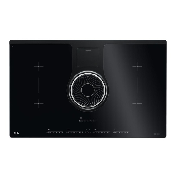
- Page 1 IDK84454IB Instruction on mounting and use...
- Page 2 EN - Safety and Regulations Strictly observe the instructions in guarantees complete disconnection of this manual. All liability is declined for the mains in overvoltage category III, in any problems, damage or fires caused by accordance with the installation rules. ● failure to comply with the instructions in Do not use power strips or extension this manual.
- Page 3 forks, spoons or lids on the device mental abilities or lacking in experience because they could become hot. ● or the necessary knowledge provided Before connecting the device to the that they are supervised or after they electrical network: check the data plate have received instruction about how to (on the bottom of the device) to ensure safely use the device and understand the...
- Page 4 length, as indicated in the installation guide. ● When the device is used together with other devices powered with non-electrical energy, negative pressure of the room must not exceed 4 Pa (4 x 10 bar). This manual must be ●5 stored for future consultation at any time.
- Page 7 2,8 m Source locally 3,5x9,5mm...
- Page 8 Eu Market ONLY. Do not remove adhesive label and wires below. min.500 min.50...
- Page 9 inst. 20 - 60mm > 50 > 50...
- Page 10 inst. 6.5 mm Source locally 25 - 60mm r 12 50 > 50 >...
- Page 11 FRONT...
- Page 13 inst. 2,8 m...
- Page 14 inst. 2,8 m...
-
Page 15: Optional Connection
OPTIONAL 220V-240V ~ CONNECTION 50Hz/60Hz 380V-415V ~ 50Hz/60Hz 380V-415V ~ 50Hz/60Hz 220V-240V ~ 50Hz/60Hz 220V 240V .a - see Chapter 3.1... - Page 16 BROWN 380V-415V ~ 2N~ 50Hz/60Hz BLACK 220V 240V GREY 220V 240V BLUE 380V-415V ~ 3N~ BROWN 50Hz/60Hz BLACK 220V GREY 240V 220V 240V 220V BLUE 240V...
- Page 18 inst.
- Page 20 7a.1 BACK FRONT 7a.3 7a.2 7a.4...
- Page 21 7a.5 7a.6...
- Page 22 inst. inst. > 50 > 50 Source locally...
- Page 23 inst. inst. > > > Source locally...
- Page 24 Ø150mm Source locally...
- Page 26 clack! 9a.1.2...
- Page 27 9a.1.3 clack!
- Page 28 3,5x9,5mm clack!
- Page 29 BACK FRONT 9a.5 9a.4 9a.6...
- Page 30 9a.7 9a.8...
- Page 31 <...
- Page 32 40,5 475,5 > 26,50 R.10...
- Page 34 > 50 > 50...
- Page 35 60/120 ≥ max 630...
- Page 36 Source locally...
- Page 37 fig.15 fig.17 fig.16 -18...
- Page 39 17.1 17.2...
- Page 44 17c.2 17c.1...
- Page 47 2,1 - 3,0 kw 2,1 - 3,0 kw ≥ Ø 110mm ≥ Ø 110mm 2,1 - 3,0 kw 2,1 - 3,0 kw ≥ Ø 110mm ≥ Ø 110mm ≥ Ø 230mm...
- Page 49 EN - Instruction on mounting and use Using the extractor fan 2. Use The extraction system can be used in two versions: external Using the hob extraction and evacuation or as a filter with internal recirculation. The induction cooking system is based on the physical phenomenon of magnetic induction.
-
Page 50: Installation
3. Installation 3.2 Mounting Before starting the installation: Both electric and mechanical installation must be carried out • After unpacking the product, check that it has not been by specialised personnel. damaged during transport and in the event of problem, The electrical appliance is designed to be built into a work top with please contact the reseller or the Customer support a thickness of 2-6 cm in the case of TOP installation;... -
Page 51: Operation
4. Operation Control panel Note: To select the commands, simply touch (press) the symbols representing them Keys Display / LED ON/OFF of the hob / extractor fan for hob 11. View Power Level Cooking zone position indicator 12. View extraction speed (power) Cooking zone selection 13. - Page 52 USING THE HOB Operation Before you begin, it is important to know: Note: Before activating any functions, the desired zone must be All functions of this hob are designed in order to comply with the activated most stringent safety regulations. For this reason: Switch-on •...
- Page 53 Warming Function The Warming Function is a control function that allows you to keep To switch-off the Timer: the heat at a constant temperature at an optimized power level; • select the cooking zone this feature is ideal for keeping ready meals warm. •...
- Page 54 Power Limitation the display (15) will show the countdown, The Power Limitation function allows the product to be used while Note: on the side of the display of the extractor fan, with the Timer limiting its maximum consumption. in use, the following symbol will appear (19) Note : the limit must be set when the hob is off, without pressing When the timer has finished the countdown, there is an acoustic...
- Page 55 4.1 Power tables Use of level Power level Cooking type (display combines the experience and cooking habits) Ideal to quickly increase the temperature of the food up to Boost Heat quickly fast boiling in the case of water or quickly heat cooking Max power liquids Ideal for browning, starting to cook, frying frozen products,...
- Page 56 4.2 Cooking tables Power level and cooking pattern Category of Dishes or type foods of cooking First stage Powers Second stage Powers Cooking pasta and Fresh pasta Heating water Booster-9 maintaining the boil Cooking pasta and Fresh pasta Heating water Booster-9 Pasta, rice maintaining the boil...
-
Page 57: Maintenance
5. Maintenance Extractor fan maintenance Hob maintenance Caution! Before any cleaning or maintenance, make sure the Cleaning cooking zones are switched off and the heat indicator has For cleaning, use ONLY a cloth moistened with neutral liquid turned off. detergents. DO NOT USE CLEANING UTENSILS OR TOOLS! Avoid the use of products containing abrasives. -
Page 58: Information Code
5.2 Troubleshooting INFORMATION CODE DESCRIPTION POSSIBLE CAUSES SOLUTION The command zone switches off due to an The temperature inside the Wait for the hob to cool excessively high temperature electronic parts is too high before reusing it ERR03 Continuous (permanent) key activation is Water, pots or kitchen tools Clean the surface, remove detected. - Page 60 LIB0170022 Ed. 10/20...