Table of Contents
Advertisement
Quick Links
Advertisement
Table of Contents

Related Manuals for Bosch rexroth IndraControl VAC 08.1


Summary of Contents for Bosch rexroth IndraControl VAC 08.1
- Page 1 IndraControl VAC 08.1 CDI+ Splitter Operating Instructions Edition 01 R911400465...
- Page 2 Edition 01, 2019-11 Refer to tab. 1-1 "Change Record" on page 1 Copyright © Bosch Rexroth AG 2019 All rights reserved, also regarding any disposal, exploitation, reproduction, edit- ing, distribution, as well as in the event of applications for industrial property rights.
-
Page 3: Table Of Contents
Connecting cables for the CDI+ interface..........6 Ambient conditions................7 Standards....................CE marking..................... 9 7.1.1 Declaration of conformity..............UL/CSA certified.................. 10 Technical data..................10 Voltage supply..................10 Digital 24 V inputs SEL and MOD............Interfaces..................... 12 R911400465_Edition 01 Bosch Rexroth AG... - Page 4 21 Commissioning..................Device description................12.1 Function of the digital inputs............... 24 12.2 Display elements.................. 25 12.3 Operating and error display..............25 Error causes and troubleshooting............26 Maintenance..................14.1 Regular maintenance tasks..............Bosch Rexroth AG R911400465_Edition 01...
- Page 5 IndraControl VAC 08.1 CDI+ Splitter Table of Contents Page Ordering information................15.1 Accessories and spare parts..............27 15.2 Type code..................... 27 Disposal....................16.1 Return....................28 16.2 Packaging..................... 29 Service and support................Index....................31 R911400465_Edition 01 Bosch Rexroth AG...
- Page 6 IndraControl VAC 08.1 CDI+ Splitter Bosch Rexroth AG R911400465_Edition 01...
-
Page 7: About This Documentation
Program Test Maintain Dispose Activities Design Install Configure Remove faults Construct Simulate Create the NC program Fig. 1-1: Assigning the present documentation to the target groups, product phases and ac- tivities of the target group R911400465_Edition 01 Bosch Rexroth AG... -
Page 8: Purpose
Operator Display Rexroth IndraControl R911341191 VDP 15.3, 18.3, 21.3 Multi Touch Operating Instructions Operator Display – Built-In Devices Rexroth IndraControl R911384713 Operating Instructions Multi-Touch Displays (Built-in Device) Tab. 1-2: Related documents on the CDI+ splitter Bosch Rexroth AG R911400465_Edition 01... -
Page 9: Customer Feedback
Please email your feedback on the documentations to Feed- back.Documentation@boschrexroth.de. Directly insert comments in the elec- tronic PDF document and send the PDF file to Bosch Rexroth. 2 Product identification and scope of delivery 2.1 Product identification The type plate is located on the rear side or at the side of the device. -
Page 10: Explaining Signal Words And Safety Alert Symbol
In case of non-compliance with this safety instruction, death or serious injury will occur. WARNING In case of non-compliance with this safety instruction, death or serious injury can occur. CAUTION In case of non-compliance with this safety instruction, minor or moderate injury can occur. Bosch Rexroth AG R911400465_Edition 01... -
Page 11: Symbols Used
Operation must only be carried out with the hardware component configura- tions and combinations that are expressly specified. The CDI+ splitter can be used for the following IndraControl V device: Control cabinet PC Rexroth IndraControl VPB 40.4 and PR4 ● Panel PC VR4 ● R911400465_Edition 01 Bosch Rexroth AG... -
Page 12: Accessories
Ordering code Part number Description RKB0008/000,5 (*******-*******-*******) R911171484 Length: 0.5 m RKB0008/001,0 (*******-*******-*******) R911171485 Length: 1 m RKB0008/002,5 (*******-*******-*******) R911170151 Length: 2.5 m RKB0008/005,0 (*******-*******-*******) R911170152 Length: 5 m RKB0008/007,5 (*******-*******-*******) R911172971 Length: 7.5 m Bosch Rexroth AG R911400465_Edition 01... -
Page 13: Ambient Conditions
Air pressure Up to 3,000 m above Up to 3,000 m above Up to 3,000 m above sea level acc. to EN sea level acc. to EN sea level acc. to EN 61131-2 61131-2 61131-2 R911400465_Edition 01 Bosch Rexroth AG... - Page 14 The devices to be installed into the housing and installation compartments ● must at least comply with the degree of protection IP 54 according to DIN EN 60529. The device shall be provided in a suitable fire enclosure in the end-use appli- ● cation. Bosch Rexroth AG R911400465_Edition 01...
-
Page 15: Standards
Part 6-4: Generic standards – Emission standard for indus- trial environments (IEC 61000-6-4:2006) DIN EN 61000-6-2 Electromagnetic compatibility (EMC) March 2006 (VDE 0839-6-2) Part 6-2: Generic standards – Noise immunity for industrial environments (IEC 61000-6-2:2005) Tab. 7-2: Standards for electromagnetic compatibility (EMC) R911400465_Edition 01 Bosch Rexroth AG... -
Page 16: Ul/Csa Certified
Emitted interference and surge immunity = 35 V (for t < 100 ms) Current consumption at U Max. 0.45 A at 24 V Input fuse None Switch-on threshold 22 V ±5 % Switch-off threshold 19 V ±5 % Bosch Rexroth AG R911400465_Edition 01... -
Page 17: Digital 24 V Inputs Sel And Mod
Nominal value at "1" 2.8 mA to 6 mA Cable length (unshielded) < 100 m Short-circuit protection, overcurrent protection Typ. 0.6 A Tab. 8-3: Characteristic values of the digital 24 V inputs SEL and MOD R911400465_Edition 01 Bosch Rexroth AG... -
Page 18: Interfaces
G-3,5THT1 ST-3,5 XUSB USB 2.0 connection to the USB socket, USB plug, Type A Type A XHDMI HDMI HDMI female connector HDMI connector XCDI+tx1 CDI+ interface to the first RJ45 socket RJ45 plug operator display Bosch Rexroth AG R911400465_Edition 01... -
Page 19: Voltage Supply And Digital 24 V Inputs
12.1 "Func- tion of the digital inputs" on page Operating the operator display as well as the USB data traffic only possible at the active operator display. The screen is always output on both operator displays R911400465_Edition 01 Bosch Rexroth AG... -
Page 20: Interfaces
– 50 mm to the bottom side – 80 mm to the upper side – 80 mm to the front side Lay all connecting cables in loops. ● Use strain reliefs for the cables. ● Bosch Rexroth AG R911400465_Edition 01... -
Page 21: Housing Dimensions
Keep at least a distance of 10 cm to high-interference cables (e.g. motor ca- ● bles) when routing HDMI, USB and CDI+ cables. Avoid parallel cable routing. 10.2 Housing dimensions The CDI+ splitter has the following dimensions: Fig. 10-2: Dimensions of the CDI+ splitter – Front view R911400465_Edition 01 Bosch Rexroth AG... -
Page 22: Mounting
Mounting, demounting and electric installation Fig. 10-3: Dimensions of the CDI+ splitter – Rear view Fig. 10-4: Dimensions of the CDI+ splitter – Side view 10.3 Mounting 1. Mounting CDI+ splitter to the rear panel Bosch Rexroth AG R911400465_Edition 01... -
Page 23: Demounting
3. Put the line into the clamping point ②. 4. Fix the line by removing the screwdriver. Fig. 10-5: Connecting the lines at X1S1 Bosch Rexroth recommends a 0.4 mm x 2.5 mm x 80 mm screwdriv- R911400465_Edition 01 Bosch Rexroth AG... -
Page 24: Line Lengths And Cross-Sections
10.5.3 Connecting 24 V DC External power supply unit A 24 V voltage supply supplies the CDI+ splitter. Use the Bosch Rexroth power supply unit VAP01.1H-W23-024-010-NN (see chap- ter 5.1 "External 24 V power supply unit" on page 6). For further information on the external power supply unit and on the creation of overvoltage categories, re- fer to the documentation of the power supply unit. -
Page 25: Connecting The Cdi+ Interface Of The Cdi+ Splitter To The Operator Display
10.6 Overall connection diagram 24 V switching input 24 V voltage supply Operator display no. 1 CDI+ X1S1 XCDI+tx1 XUSB CDI+ splitter display port XHDMI XCDI+tx2 Operator display no. 2 CDI+ Fig. 10-6: Connecting the CDI+ splitter R911400465_Edition 01 Bosch Rexroth AG... -
Page 26: Mounting Recommendation For Cdi+ Cables With Long Lengths In An Interference-Prone Environment
In most cases, a connection via the RJ45 connectors is sufficient. Remove any collection of dirt from the shield surfaces of the RJ45 plugs before plugging them in. Bosch Rexroth AG R911400465_Edition 01... -
Page 27: Additional Shielding Connection In Case Of Strong Electrical Interfer- Ences And Long Cables
The CDI+ cable is sensitive to mechanical load where the jacket was removed. Ensure that the CDI+ cable shielding is not damaged when removing the cable jacket. Fig. 10-8: CDI+ cable with RJ45 plug R911400465_Edition 01 Bosch Rexroth AG... - Page 28 The plastic coating is insulating. Fig. 10-10: Foil shield of the CDI+ cable Fig. 10-11: Foil shield removed 3. Fasten cable with EMC shielding clamp. Fig. 10-12: CDI+ cable with shielding clamp More shielding clamps: Bosch Rexroth AG R911400465_Edition 01...
-
Page 29: Commissioning
12 Device description Two operator displays can be connected to one PC using a CDI+ splitter. All op- erator displays show the same screen. The operation depends on the wiring of the inputs "SEL" and "MOD". R911400465_Edition 01 Bosch Rexroth AG... -
Page 30: Function Of The Digital Inputs
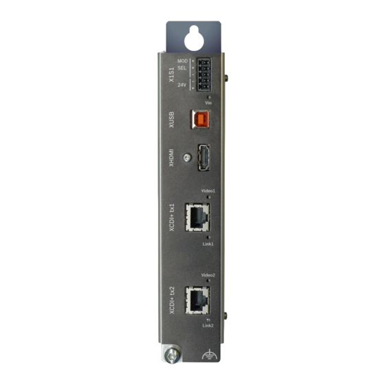
Operating state, operator display 1 ⑧ CDI+ interface to the first operator dis- play Fig. 12-1: Connector panel of the CDI+ splitter 12.1 Function of the digital inputs Operator display 1 (XCDI+tx1) Operator display 2 (XCDI+tx1) Active Active Bosch Rexroth AG R911400465_Edition 01... -
Page 31: Display Elements
Operator panel not selected, but the and red communication is possible with the operator panel LED off No communication possible with the operator display, even though it is ac- tive (selected via SEL or MOD) R911400465_Edition 01 Bosch Rexroth AG... -
Page 32: Error Causes And Troubleshooting
Tab. 13-1: Error causes and troubleshooting Repairs at the device by the customer are not permitted. Exceptions are maintenance works listed in the chapter "Maintenance". For further information in the event of repair, please contact the Bosch Rexroth Service. Bosch Rexroth AG R911400465_Edition 01... -
Page 33: Maintenance
For ordering information on accessories and spare parts, refer to chapter 5 "Ac- cessories" on page 15.2 Type code The CDI+ splitter with CDI+ interface is available in different variants according to the following type code: R911400465_Edition 01 Bosch Rexroth AG... -
Page 34: Disposal
Furthermore, the products returned for disposal must not contain any undue for- eign substances or external components. Send the products free of charge to the following address: Bosch Rexroth AG R911400465_Edition 01... -
Page 35: Packaging
Detailed description of malfunction and circumstances ● Type plate specifications of the affected products, in particular type codes ● and serial numbers Your contact data (phone and fax number as well as your e-mail address) ● R911400465_Edition 01 Bosch Rexroth AG... - Page 36 30/33 IndraControl VAC 08.1 CDI+ Splitter Bosch Rexroth AG R911400465_Edition 01...
-
Page 37: Index
Customer Feedback......3 Interference-prone environ- ment..........20 Interferences, electrical....21 Declaration of conformity....9 Degree of protection..... 10 Demounting........17 LEDs..........25 Device description......23 Line cross-sections....... 18 Digital 24 V inputs......13 Line lengths........18 R911400465_Edition 01 Bosch Rexroth AG... - Page 38 SEL......... 11, 18 Service hotline......29 Shielding........20 Shielding CDI+ cable....20 Shieling clamps......22 Shock..........8 Signal alert symbol......4 Signal words........4 Standards........9 Suggestions........3 Support........29 Switching input......13 Symbols.......... 5 Bosch Rexroth AG R911400465_Edition 01...
- Page 39 IndraControl VAC 08.1 CDI+ Splitter 33/33 Notes...
- Page 40 Bosch Rexroth AG Electric Drives and Controls P.O. Box 13 57 97803 Lohr, Germany Bgm.-Dr.-Nebel-Str. 2 97816 Lohr, Germany Phone +49 9352 18 0 Fax +49 9352 18 8400 www.boschrexroth.com/electrics *R911400465* R911400465 DOK-SUPPL*-VAC*08.1***-IT01-EN-P...