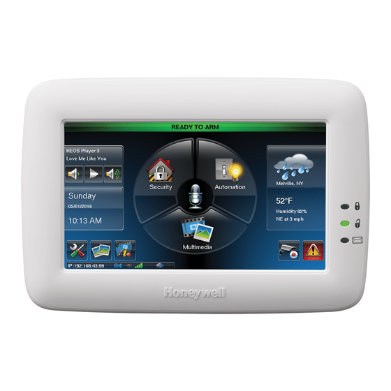
Honeywell Tuxedo Touch WIFI Quick Installation Manual
Home automation system
Hide thumbs
Also See for Tuxedo Touch WIFI:
- User manual (64 pages) ,
- Installation and setup manual (48 pages)
Advertisement
Quick Links
Tuxedo Touch
Quick Installation Guide
Controller Initial Setup Wizard
When initially powered (or factory defaulted), the initial boot sequence has 8
easy steps:
1. "Operational Mode." Choose the Operation Mode (Languages, Blank Display
[see below] and Operating Mode) options.
2. "Set ECP and RIS Address" is displayed. If using one keypad, leave the ECP
address set to 1. If using more than one, power-up each keypad one at a
time > set each keypad ECP address to the appropriate address. Verify the
RIS address the panel programming and AlarmNet Communicator (if
required).
3. Review the "Honeywell Privacy Statement and End User License Agreement."
4. Configure the Wireless or LAN connection.
5. Fill in all fields of the "Important Operation Information" screen.
6. If using remote or local login from a PC or Smart Device, create up to 5
username and passwords and select "Authentication for Web Server Local
Access" (defaulted enabled) if an access username and password are require
for local access.
7. Review the Voice Disclaimer/Limitations of Liability and Tutorial Video.
8. If using the voice feature, participate in the interactive voice tutorial.
Installer Note: The Tuxedo Touch Screen is factory calibrated. Ignore the
"CALIBRATE" button that appears after ECP setup.
(EN50131 DISPLAY)
SCREEN BLACKOUT
The Screen Blackout (EN50131 Display) compliance feature is a European
Standard designed to prevent unauthorized users from viewing the status of the
Security System by blanking the screen after 30 seconds, to enable: Press
Setup > System > CS Setup > Enter an Authorized Code, if required > Options
> Select EN50131 Display to turn the option on or of > Apply.
– Change the ECP Address
ECP ADDRESS
If the screen is displaying "ECP Error," the ECP address in the keypad is not
valid or is not enabled in the panel's programming. In this case, to change the
ECP Address, enter the default code of "4140" to advance to the next screen.
Note: When the keypad displays "ECP Error" the default code is "4140." Once
connected to a control panel, use that panel's installer code.
To change the address: press Setup > System > CS Setup > enter an Authorized
Code, if required > ECP Address; use the Up/Down arrows to select a new
address.
The available ECP addresses are:
1-2, 5-6.....for residential controls.
1-2, 3-30...for commercial controls under Rev. 10; supports 3 AUIs. *See
Important Note below.
1-30 ....... for commercial controls Rev. 10 or higher (Vista-Turbo Panels); which
support 6 AUIs.
*IMPORTANT NOTE: If multiple keypads are being used, they must be set to
addresses 1, 2, and X (where X equals any address from 3 through 30). Only
one AUI type (touch screen) device may be assigned to an address from 3
through 30 on NON-Vista-Turbo commercial control panels.
– Set the current time and date
DATE AND TIME
Press Setup > System > Time/Date Setup > enter an "Authorized Code" >
press Apply and answer Yes to the next prompt.
a) If Get Time is pressed, the keypad retrieves the time/date from the control
panel and exits the 'Set Time' screen. (The Get Time icon appears with
residential panels and may not appear with all commercial panels.)
b) Or, set the time/date from the Set Time/Date screen.
- Adjust display
DISPLAY & AUDIO SETUP
1. Press Setup; slide the Brightness / Volume bar up or down to change
settings. Press the Back icon and then Yes to save.
2. Press Setup > Disp & Audio Setup > enter an Authorized Code > Save.
- To adjust the screen timeouts, highlight the option and select a time interval
using the up/down arrows for each option (Backlight Off After, To
Homepage After and Auto Slideshow After). Select the Temperature Unit.
- Select Chime, Voice or Voice Chime operating mode.
- To clean the keypad screen, press the Clean Screen icon; press Continue,
or press Cancel to exit.
- Add a User
USER SETUP
Press Setup > System > User Setup > Add User > enter an Authorized Code;
select each field and enter the appropriate information > Save.
For available user numbers, see control panel instructions.
- View authority levels
SCREEN SECURITY
Screen Security provides a choice to which screen can be protected with a code
consisting an authority level you choose.
See the full Installation Guide for user Authority Levels.
1. Press Setup > System > CS Setup.
2. Enter an Authorized Code and press Screen Security.
- To make changes, select the line to change and the level of user to have
access, and then press Apply.
– View users / authority levels
CODE AUTHORITY
Press Setup > System > CS Setup > Code Authority > enter the 4-digit Code
for the user you want to obtain authority level information.
SYSTEM INFORMATION / UPGRADES
To view the current software version installed, and verify connectivity, press
Setup > System Information
.
Software upgrades may be available. To manually upgrade with an SD card, log
into www.TuxedoTouchToolKit.com and following the instructions provided.
Automatic updates are available are available by enabling the "Enable Remote
Upgrade" option.
– Set a location
WEATHER FORECAST
1. Press the Weather feature on the "Home" screen.
2. Select USA, Canada or Other Zip Code/Postal Code and enter the
information on the data entry keyboard.
IP SETUP – Set the IP Address
The Tuxedo Touch Keypads IP Address is used on a standard web browser to
control user functions such as Security, Z-Wave operation, and camera viewing.
1. Press Setup > IP Setup.
2. Select a type of network connection: LAN ON or WIFI ON.
System Setup
Clean Screen
CS Setup
System Information
Account Login
System
Camera Wi-Fi
W
i
-
F
i
W
i
-
F
i
®
®
Home Automation System
™
Full Installation Guide [Part Number 800-16571V2 8/15] available online at: www.MyWebTech.Honywell.com.
For LAN ON (default selection):
- Connect an Ethernet cable between the router and the Keypad; the IP address
and default gateway address of the router is displayed.
- If the IP address is not displayed, change the "Internet Connection Type" to
Static and manually enter the necessary IP information from your router onto the
keypad.
- Press Save.
For WIFI ON:
- Press WIFI ON; a local WIFI list is displayed. Select the desired WIFI router and
enter the Passphrase/Shared Key (if applicable).
- If the WIFI router is not broadcasted, scroll to the bottom of the list and select Add
Network; enter your SSID and if applicable, the Security
Mode/Passphrase/Shared Key.
- Press Save.
Notes:
Pressing "Save" after changing the port number resets the keypad.
•
To view connectivity, press the System Information icon (see section above).
•
If left inactive, Web connections disconnect after 10 minutes.
•
3 failed login attempts will disable the remote access feature. To reset, access the
•
"Account Login" page through the Tuxedo.
3. Press Account Setup to create a browser log-on page for each user (for higher
security) when viewing from a web enabled device or PC on a different sub-net.
Enter the required information for each field; press Save.
AUTOMATION – Enroll / Add Z-Wave devices
Add a Z-Wave
Water Valve and Shades:
See the "Programming of Z-Wave Devices" Training Video.
1. Install device according to the manufacturer's directions.
2. Press Automation > Z-Wave Setup > Add Device.
3. Press the Function Key on the device (defined in the devices installation
instructions); follow the keypads on-screen messages until "Device added
successfully" displays.
4. To verify activation: on the Tuxedo Touch Keypad, press Back; wait 30 seconds.
Press Refresh; the new device is displayed.
See full Installation Guide to view other important Z-Wave information (Including
adding/deleting Secondary Keypads).
Changing the Device Name/Icon
As a device is enrolled, many devices learn in as a default icon and name. To change
the name and icon of the device (from the Z-Wave Device Management Screen) select
the device and press Device Setup. NOTE: Controllers cannot be edited, only Binary,
Multilevel switches and Water Valves. See the table below for icon options.
Z-Wave Device Grouping (For Scene Activations)
After all Z-Wave devices have been enrolled into the Primary Keypad (Controller #1) or
secondary keypad.
1. Press Automation > Grouping > Add.
2. Press Group Name and enter the desired name.
3. Press Group Type and select Binary, Thermostat, Door Lock, Multilevel Switch,
Garage Door, Water Valve, Shade, or Other.
4. Select the device(s) to add and Press Save.
SCENE SETUP – Define (up to 30) Scenes
The Scene feature is used to control a single device, or multiple devices based on pre-
set "Conditions," "Triggers," and "Actions." When a trigger/condition occurs, the
defined action is executed.
1. Press Automation > Scene Setup > Add.
2. Press Scene Name; enter a "Name" and press OK.
3. Add the "Condition," "Trigger," and "Action" that is to occur for this Scene (see
below).
4. After each selection press Save!!
Note: Determine if you need a Condition. The Condition must occur prior to a trigger
event. See example below:
Example: Turn the lights on when the system disarms, but only at night.
(Condition) ... "only at Night" ....Set the TIME Condition (enter the Start Time and
Duration).
(Trigger) ...when the "system Disarms" ...Set the Trigger to SECURITY: System
Disarm
(Action) ...Turn the "lights ON" ... Set the Action to LIGHT: ON.
Scene Rules
• Triggers and Conditions include: Time setting Occurrence/Days/Start Time,
Security mode Disarm/Night/Away/Stay/Away Secured, Thermostat setting
Above/Below/Temperature Value, Door Unlocked/Locked/ Code Unlocked Status,
Garage Door Opened/Closed, Water Valve Opened/Closed, and Zones
Restore/Alarm/Fault.
• Actions include choosing Security mode Disarm/Night/Away/Stay/Disarm With
Code (enter User Code), Thermostat setting Set Mode/Set Energy/Set Point,
Door Unlocks/Locks, Garage Door Open/Close, Water Valve Open/Close,
Recording (List the camera's and choose the camera which will record [see
"Camera" section, and Email and choose the email addresses and create a custom
message. NOTE: Each Trigger event can have up to 5 Actions.
NOTES:
• A Trigger event and Condition cannot be the same (i.e., if setting a Trigger event
for SECURITY, you cannot set a SECURITY Condition).
• Each Tuxedo supports 30 scenes local, with the ability to review 20 scenes
configured in Total Connect. (Editing scenes through Total Connect requires an
"Administrative" login to Total Connect).
• Some Actions allow you to select a single device or a group of devices, which is
configured on the "Z-Wave Device List" screen.
• Warning: Leak Gopher® Water Valve does not send status to the keypad when
manually operating.
TOTAL CONNECT REMOTE ACCESS SETUP
This option requires a Wi-Fi connection.
• Configure you remote access option on your AlarmNet Communicator.
• Verify the remote keypad ECP address and RIS match what is programmed in the
panel.
• The RIS option must be enabled in the panel for successful "Panel Sync," executed
through Total Connect.
• Verify all Z-Wave devices are enroll and functional in the keypad.
TOTAL CONNECT Z-WAVE SETUP/CONTROL
"Automation" must be enabled through the AlarmNet Communicators Total Connect
Service. Total Connect supports 40 lights (including Water Valves), 3 thermostats and
4 door locks and 3 Garage Door Controllers.
To enabled the specific Z-Wave device press Setup > System > CS Setup > Enter
Authorized Code > TC SERVER INFO > TC Enable Icon
Z-Wave
Refresh
Primary Controller
Setup
Email
Home Page
Group
Software
Download
Available
NOTE: This device is a Security Enabled Z-Wave Controller
Light Switch, Thermostat, Door Lock, Garage Door Controller,
®
.
Icon Reference Table
Secondary
Scene Setup
Add Scene
Controller
Display and Audio
Screen Security
IP Setup
Setup
PANEL CONFIGURATION–View system details
1. Press Setup > System > CS Setup.
2. Enter an Authorized Code and press Panel Config.
- Delete clears the keypad and reloads the panel configuration into the
keypad (the keypad will reboot).
MULTI-MEDIA – Picture, Video, Camera Setup
Review the Quick User Guide or full Installation Guide for Picture and
Video setup.
Camera Setup:
• If using existing (mounted) cameras; go to Step 4.
• If this is a first time setup, scan/configure the cameras prior to
mounting, and then do the following:
1. Connect an Ethernet cable to the back of the camera (LAN); connect the
opposite end to the Ethernet port on the router.
2. Apply power to the camera; wait for initial power-up.
3. Press Multi-Media > Camera > Camera Setup.
4. Press Discover to locate the camera. The screen displays
"Discovering Cameras Please Wait..."
Note: For best performance set video resolution to 320 x 240, 8 frames
per sec.
5. Press Add if the camera information is not discovered automatically, to
enter information manually.
6. To edit camera information, highlight the camera name and press Edit.
Enter required information and then press Save.
a) To retrieve camera settings and connect to the camera, press Connect.
b) Press Total Connect to reset the camera to the Total Connect for
remote viewing.
c) Press Reset to reset the camera to factory default. Select Yes or No.
7. When all cameras have been added, press Camera WIFI and enter the
wireless information from the router.
8. Press Apply to All to set cameras to wireless operation.
9. Press Settings to enter advanced settings for Video, Network, Wireless
and Other settings.
10. Remove Ethernet cable from wireless cameras to view wirelessly via
the Keypad. If the camera does not have wireless capability, leave the
camera connected.
Use the icons to: Delete/Delete ALL > Play > Stop
Auto Pan
> Quad View
> Back
.
Notes:
1. QuickTime® media player must be installed on your PC.
2. Camera viewing is compatible with IE8 (and above) and Safari 5.0
(and above); and not compatible w/Opera web browsers or Chrome
version 42 or higher.
3. Do not use ports 6665-6669 for camera HTTP configuration.
E-Mail Notifications
Review the Full Installation Guide for detailed Normal Mode and
Automation mode email set up information. Note: "Email notification is
strictly for convenience use only. Avoid relying on this feature for life
critical events. It is not UL certified and may fail at any time without
notice."
1. Add an email address (The email address in which the notification will
generate from): Press Setup > E-Mail > User SMTP.
2. Enter The "E-Mail Server Name," "E-Mail ID," "Password," "E-Mail
Server," and "SMTP PortNum."
3. Press Save > Back.
4. Choose Event 1-4.
5. Select the event and trigger in which the notification is to be sent. The
options are "Security," "Zones," "Thermostat," "Door Lock," "Garage
Door," "Water Valve," and "Recording."
6. Press E-Mail Address and enter up to 4 email addresses.
Example: Configure an email for Security Arming Away/Disarm/Alarm,
Door locked/Unlocked, Recording on an established event (set in scenes in
"Camera Setup," and "Scenes").
1. Press the check box next to Security, Door Lock, and Recording.
2. Press Security then the check boxes next to Disarm, Away Secured,
and Alarm.
3. Press Door Lock, and then from the drop down list select the door lock.
(NOTE: To send emails for additional locks, another event must be
created (total events are 4). Select the check box next to Locked and
Unlocked.
4. Press Recording and check the box next to On Event Recording.
5. Press Save.
Account Setup – Remote Login
Local remote login is accessed by entering the IP address in the bottom left
had corner on the smart devices web browser, if connected to the same
network. The other option is to enter HTTP://Tux.MyLanConnect.com.
NOTE: If the "Secured Web Server Access (HTTPS)" option is enabled on
the Account Setup screen, the address will be
HTTPS://Tux.MyLanConnect.com. A list of the keypad connected to the
same network appear. Press the IP address to access the Tuxedo's home
screen. Remote Access through an outside network requires port forward
configuration on the router. After referring to the router, enter the external
IP address: port number that is forwarded to access the Tuxedo's home
screen.
U L Notes
• Email Notifications are supplementary only and have not been evaluated
by UL.
• Automatic Software Updates are not applicable for UL applications.
• Wi-Fi has not been evaluated for UL applications.
• Voice Input Commands are supplementary and not evaluated for UL
applications.
• Remote arming/disarming/programming is not to be used in UL Listed
Installations.
USE OF THESE PRODUCTS IN COMBINATION WITH NON-HONEYWELL
PRODUCTS IN A WIRELESS MESH NETWORK, OR TO ACCESS, MONITOR OR
CONTROL DEVICES IN A WIRELESS MESH NETWORK VIA THE INTERNET OR
ANOTHER EXTERNAL WIDE AREA NETWORK, MAY REQUIRE A SEPARATE
LICENSE FROM SIPCO, LLC. FOR MOREINFORMATION, CONTACT SIPCO, LLC
OR IPCO, LLC AT 8215 ROSWELL RD., BUILDING 900, SUITE 950, ATLANTA, GA
303350, OR AT WWW.SIPCOLLC.COM OR WWW.INTUSIQ.COM
Camera Setup Camera Recording Camera Discover
Z-Wave Device Icon Options
Dimmable
On/Off
Garage
Sprinkler
Pool
Light
Light
> Refresh >
> Full View
> Pan/Tilt
Connect
Total Connect
Reset
Water
Siren
Shade
Sounder
Fan
Valve
Advertisement

Related Manuals for Honeywell Tuxedo Touch WIFI


Summary of Contents for Honeywell Tuxedo Touch WIFI
- Page 1 • If using existing (mounted) cameras; go to Step 4. Network; enter your SSID and if applicable, the Security 3. Review the “Honeywell Privacy Statement and End User License Agreement.” • If this is a first time setup, scan/configure the cameras prior to Mode/Passphrase/Shared Key.
- Page 2 For the latest documentation and online support information, please 2 Corporate Center Drive, Suite 100 go to: P.O. Box 9040, Melville, NY 11747 https://mywebtech.honeywell.com/ Copyright © 2014 Honeywell International Ê800-16603V24Š For the latest warranty information, please go to: www.honeywell.com/security Warranty www.honeywell.com/security/hsc/resources/wa.