Table of Contents
Advertisement
Quick Links
SERVICE MANUAL
Ver. 1.0 2009.07
• ATS-SW10Ti is the amplifi er, tuner, speaker and iPod/iPhone section in AIR-SW10Ti.
• When the operation of the ATS-SW10Ti or SA-WA10R is confi rmed, it is necessary to communicate
the set of both and confi rm.
Confi rm that all units included in AIR-SW10Ti are prepared beforehand when you repair.
• "S-AIR" and its logo are trademarks of Sony Corporation.
• iPod is a trademark of Apple Inc., registered in the U.S. and other countries.
• iPhone is a trademark of Apple Inc.
• The Bluetooth word mark and logos are owned by the Bluetooth SIG, Inc. and any use of such marks by Sony Corporation is
under license. Other trademarks and trade names are those of their respective owners.
• All other trademarks and registered trademarks are of their respective holders. In this manual, ™ and
AUDIO POWER SPECIFICATIONS
POWER OUTPUT AND TOTAL HARMONIC DISTORTION:
(The United States model only)
With 8 ohm loads, both channels driven, from 200 − 15,000 Hz;
rated 5 watts per channel minimum RMS power, with no more
than 10% total harmonic distortion from 200 milliwatts to rated
output.
Amplifier section
DIN power output (rated):
5 + 5 watts (8 ohms at 1 kHz, DIN)
Continuous RMS power output (reference):
5 + 5 watts (8 ohms at 1 kHz, 10% THD)
Tuner section
FM stereo, FM superheterodyne tuner
Tuning range:
87.5 − 108MHz (100kHz step)
Antenna:
FM lead antenna
Antenna terminals:
75 ohms unbalanced
Intermediate frequency:
10.7 MHz
Speaker section
Speaker system:
Full-range, 60 mm, cone type
Rated impedance:
8 ohms
Sony Corporation
9-889-587-01
2009G05-1
Audio&Video Business Group
©
2009.07
Published by Sony Techno Create Corporation
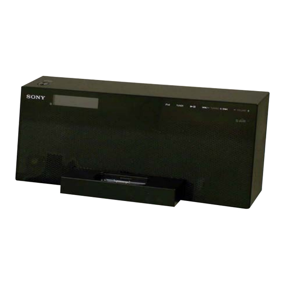
ATS-SW10Ti
®
marks are not specifi ed.
SPECIFICATIONS
iPod/iPhone section
Compatible iPod/iPhone models:
iPod nano
iPod touch
4th generation
iPhone 3G
(video)
2nd generation
iPod nano
3rd generation
iPod classic
(video)
iPod touch
1st generation
iPod nano
2nd generation
iPhone
5th generation
(aluminum)
iPod nano
iPod
1st generation
4th generation
4th generation
(color display)
WIRELESS AUDIO TRANSMITTER
iPod mini
General
Power requirements:
120V AC, 60Hz
Power consumption:
15 watts
Dimensions (w/h/d):
Approx. 310 × 121 × 162 mm
Mass:
Approx. 1.7 kg
Design and specifications are subject to change without notice.
iPod
(video)
iPod
US Model
Advertisement
Table of Contents

Related Manuals for Sony ATS-SW10Ti


Summary of Contents for Sony ATS-SW10Ti
- Page 1 • iPhone is a trademark of Apple Inc. • The Bluetooth word mark and logos are owned by the Bluetooth SIG, Inc. and any use of such marks by Sony Corporation is under license. Other trademarks and trade names are those of their respective owners.
-
Page 2: Table Of Contents
COMPONENTS IDENTIFIED BY MARK 0 OR DOTTED LINE WITH MARK 0 ON THE SCHEMATIC DIAGRAMS AND IN THE PARTS LIST ARE CRITICAL TO SAFE OPERATION. REPLACE THESE COMPONENTS WITH SONY PARTS WHOSE PART NUMBERS APPEAR AS SHOWN IN THIS MANUAL OR IN SUPPLEMENTS PUBLISHED BY SONY. -
Page 3: Servicing Notes
ADVANCE PREPARATION WHEN CONFIRMING OP- ERATION When the operation of the ATS-SW10Ti or SA-WA10R is con- fi rmed, it is necessary to communicate the set of both and confi rm. Confi rm the ATS-SW10Ti, SA-WA10R and EZW-RT10A are pre- pared beforehand when you repair. - Page 4 ATS-SW10Ti MAIN BOARD SERVICE POSITION MAIN board IPOD board DISPLAY BOARD SERVICE POSITION IPOD board MAIN board DISPLAY board POWER board block...
- Page 5 ATS-SW10Ti LEAD WIRE SETTING – speaker wire – – power cord – The wire is made double to roll. 50 mm coating clip cabinet (rear) tape clamp filter – rear side wires and flexible flat cables – print side tape...
-
Page 6: Disassembly
ATS-SW10Ti SECTION 2 DISASSEMBLY • This set can be disassembled in the order shown below. 2-1. DISASSEMBLY FLOW 2-2. CABINET (REAR) BLOCK (Page 6) 2-3. MAIN BOARD 2-4. TUNER (FM) BLOCK (Page 7) (Page 7) 2-5. POWER BOARD BLOCK (Page 8) 2-6. -
Page 7: Main Board
ATS-SW10Ti 2-3. MAIN BOARD Note: This illustration sees the set from rear side. 9 connector (CN503) 8 flexible flat cable (19 core) (CN402) 7 two connectors (CN202, CN405) 1 flexible flat cable (9 core) (CN502) 4 connector (CN602) 6 speaker connector... -
Page 8: Power Board Block
ATS-SW10Ti 2-5. POWER BOARD BLOCK Note: This illustration sees the set from rear side. 3 POWER board block 1 screw (BVTP2.6 1 two screws (BVTP2.6 2 connector (CN802) 2-6. KEY BOARD Note 1: This illustration sees the set from rear side. -
Page 9: Test Mode
3. Press the [ENTER] button on the remote commander, S-AIR tween microcomputer and EZW-RT10A is normal, “OK” is version of the set connected with ATS-SW10Ti is displayed on displayed. When abnormality is found, “NG” is displayed. the liquid crystal display. - Page 10 ATS-SW10Ti 3-8. DARR setting check 3-12. Display of recording permission information This mode is setting of EZW-RT10A is confi rmed. This mode is confi rmed whether it is a recording prohibition of the Procedure: music source the reproduction. 1. Enter the S-AIR test mode.
-
Page 11: Electrical Check
ATS-SW10Ti SECTION 4 ELECTRICAL CHECK FM TUNE LEVEL CHECK signal generator Procedure: 1. Turn on the set. 2. Input the following signal from signal generator to FM antenna input directly. Carrier frequency : A = 87.5 MHz, B = 98 MHz, C = 108 MHz... - Page 12 ATS-SW10Ti MEMO...
-
Page 13: Diagrams
ATS-SW10Ti SECTION 5 DIAGRAMS 5-1. BLOCK DIAGRAM - MAIN Section - CN601 CN300 A/D CONVERTER EZW-RT10A (iPod CONNECTOR) IC631 LINE AMP LINE-OUT-L VINL DOUT 9 SDIN_A IC2380 R-CH VINR BCK 8 R-CH LINE-OUT-R R-CH LRCK 7 MUTING SCKI 6 Q403... -
Page 14: Block Diagram
ATS-SW10Ti 5-2. BLOCK DIAGRAM - PANEL, POWER SUPPLY Section - SYSTEM CONTROLLER IC400 (2/2) BZ591 O-BUZZER LCD-SDA ND7510 LCD-SCLK LIQUID LCD-CSB CRYSTAL DISPLAY D752 LED DRIVE O-LCD_LED LCD BACK +3.3V Q752 LIGHT DSP D+3.3V REGULATOR IC502 POWER_MONITOR3 52 D700 DSP D3.3V_ON 83... - Page 15 ATS-SW10Ti THIS NOTE IS COMMON FOR PRINTED WIRING BOARDS AND SCHEMATIC DIAGRAMS. (In addition to this, the necessary note is printed in each block.) For Printed Wiring Boards. For Schematic Diagrams. Note: Note: • X : Parts extracted from the component side.
- Page 16 ATS-SW10Ti • Circuit Boards Location P_BUTTON board DISPLAY board POWER board LED board TUNER (FM) KEY board MAIN board IPOD board REG board BUZZER board...
-
Page 17: Schematic Diagram - Main Section (1/4)
ATS-SW10Ti 5-3. SCHEMATIC DIAGRAM - MAIN Section (1/4) - • See page 28 for IC Block Diagrams. MAIN BOARD (1/4) IPOD BOARD CN300 CN404 (iPod CONNECTOR) D.GND DGND Q407 C420 C418 D.GND RT1N141C-TP-1 DGND 6.3V BUFFER R552 VBUS TPA+(1394DATA) R491... -
Page 18: Schematic Diagram - Main Section (2/4)
ATS-SW10Ti 5-4. SCHEMATIC DIAGRAM - MAIN Section (2/4) - • See page 25 for waveforms. • See page 28 for IC Block Diagrams. • See page 29 for IC Pin Function Description. MAIN BOARD (2/4) CN402 SIRCS CL422 LCD-CSB R561... -
Page 19: Schematic Diagram - Main Section (3/4)
ATS-SW10Ti 5-5. SCHEMATIC DIAGRAM - MAIN Section (3/4) - • See page 25 for waveforms. • See page 28 for IC Block Diagrams. • See page 29 for IC Pin Function Description. WIRLESS TRANSCEIVER (EZW-RT10A) C705 C704 C702 CN601 L601... -
Page 20: Schematic Diagram - Main Section (4/4)
ATS-SW10Ti 5-6. SCHEMATIC DIAGRAM - MAIN Section (4/4) - • See page 29 for IC Pin Function Description. MAIN BOARD (4/4) Q202 Q204 ISA1235AC1TP-1EF ISA1235AC1TP-1EF Q202, Q204 OVER LOAD DETECT R226 220k C230 R224 R228 100k 220k R217 /DC-DET Q203... -
Page 21: Printed Wiring Boards - Main Section (1/2)
ATS-SW10Ti 5-7. PRINTED WIRING BOARDS - MAIN Section (1/2) - • See page 16 for Circuit Boards Location. • : Uses unleaded solder. BUZZER BOARD BZ591 W591 R598 D599 C599 R599 (11) 1-880-461- KEY BOARD CN702 (Page 23) MAIN BOARD... -
Page 22: Printed Wiring Boards - Main Section (2/2)
ATS-SW10Ti 5-8. PRINTED WIRING BOARDS - MAIN Section (2/2) - • See page 16 for Circuit Boards Location. • : Uses unleaded solder. IPOD BOARD IPOD BOARD (SIDE A) (SIDE B) R557 R559 C588 R556 R558 CN300 W301 (iPod CONNECTOR) -
Page 23: Printed Wiring Boards - Panel Section
ATS-SW10Ti 5-9. PRINTED WIRING BOARDS - PANEL Section - 5-10. SCHEMATIC DIAGRAM - KEY Board - • See page 29 for IC Pin Function Description. • See page 16 for Circuit Boards Location. • : Uses unleaded solder. KEY BOARD... -
Page 24: Schematic Diagram - Panel Section
ATS-SW10Ti 5-11. SCHEMATIC DIAGRAM - PANEL Section - DIAPLAY BOARD ND7510 LIQUID CRYSTAL DISPLAY LED BOARD C750 100p 100p JL001 C751 IC750 JL002 R764 R758 R764 R762 R761 6.8k 6.8k C753 100p R763 REMOTE CONTROL RECEIVER D751 D750 SDFW04052B1 IC750... -
Page 25: Printed Wiring Boards - Power Supply Section
ATS-SW10Ti 5-12. PRINTED WIRING BOARDS - POWER SUPPLY Section - • See page 16 for Circuit Boards Location. • : Uses unleaded solder. • Waveforms – MAIN Board – IC400 oa (XT2) REG BOARD 2.2 Vp-p 30.6 s 1 V/DIV, 10 s/DIV... -
Page 26: Schematic Diagram - Reg Board
ATS-SW10Ti 5-13. SCHEMATIC DIAGRAM - REG Board - • See page 28 for IC Block Diagrams. REG BOARD CN801 MAIN BOARD Q801 (4/4) 12.9 2SJ530S-TL Q801, Q802 CN202 B+ SWITCH (Page 20) Q802 2SC3052EF-T1-LEF CN803 12.9 R817 S-AIR_TAKE.GND R819 MAIN BOARD S-AIR_TAKE.3.3V... -
Page 27: Schematic Diagram - Power Board
ATS-SW10Ti 5-14. SCHEMATIC DIAGRAM - POWER Board - • See page 28 for IC Block Diagrams. POWER BOARD F901 CN904 L902 T1AH 250V LINE FILTER CL904 C913 FH901 FH902 T901 (AC IN) 220p POWER TRANSFORMER CL905 250V TH901 D901 C915... - Page 28 ATS-SW10Ti • IC Block Diagrams – MIAN Board – IC402 R5523N001B-TR-F IC501, 502 TK11133CSCL-G IC803 TK11133CSCL-G IC804 TK11185CSCL-G 5 OUT IC805 TK11190CSCL-G GATE CURRENT CONTROL LIMIT OVER HEAT & 4 IN OVER CURRENT PROTECTION OVER HEAT & UVLO OVER CURRENT...
- Page 29 ATS-SW10Ti • IC Pin Function Description MAIN BOARD IC101 CXD9926ATQ (DIGITAL AUDIO PROCESSOR) Pin No. Pin Name Description DVDD_PWM2 Power supply terminal Not used PWM2_RD Digital audio signal output terminal Not used PWM2_RI Digital audio signal output terminal Not used PWM3_LD Digital audio signal output to the digital power amplifi...
- Page 30 ATS-SW10Ti Pin No. Pin Name Description AVSS_ADC/REF Ground terminal LINEIN7L Analog audio (L-ch) signal input terminal Not used LINEIN7R Analog audio (R-ch) signal input terminal Not used AVDD_ADC Power supply terminal (+3.3V) LINEIN8L Analog audio (L-ch) signal input terminal Not used...
- Page 31 ATS-SW10Ti MAIN BOARD IC201 TAS5602DCAR (DIGITAL POWER AMPLIFIER) Pin No. Pin Name Description 1 to 3 PGNDA Ground terminal 4 to 6 PVCCA Power supply terminal (+13V) Not used DVDD Power supply terminal (+3.3V) DGND Ground terminal PWM_AP Audio signal input from the digital audio processor...
- Page 32 O-LCD_LED LED drive signal output terminal for liquid crystal display back light “H”: LED on O-SONY_LED LED drive signal output terminal for SONY indicator “H”: LED on O-POWER_LED LED drive signal output terminal for STANDBY indicator “H”: LED on...
- Page 33 ATS-SW10Ti Pin No. Pin Name Description Power supply on/off control signal output terminal for DAB tuner +1.2V power supply O-DAB-PWR1.2V Not used Power supply on/off control signal output terminal for DAB tuner +3.3V power supply O-DAB-PWR3.3V Not used Not used...
- Page 34 ATS-SW10Ti KEY BOARD IC700 ATA2508DC-30S (TOUCH SENSOR CONTROLLER) Pin No. Pin Name Description RESET_N Reset signal input from the system controller “L”: reset ID selection signal input terminal Fixed at “L” in this set 3 to 8 DIO_5 to DIO_0...
-
Page 35: Exploded Views
ATS-SW10Ti SECTION 6 EXPLODED VIEWS Note: • -XX and -X mean standardized parts, so • The mechanical parts with no reference The components identifi ed by mark 0 they may have some difference from the number in the exploded views are not sup- or dotted line with mark 0 are critical for original one. -
Page 36: Power Block Section
ATS-SW10Ti 6-2. POWER BLOCK SECTION Note: This illustration sees the set from rear side. not supplied not supplied (POWER board) F901 speaker section not supplied not supplied not supplied not supplied not supplied not supplied not supplied not supplied not supplied... -
Page 37: Speaker Section
ATS-SW10Ti 6-3. SPEAKER SECTION Note: This illustration sees the set from rear side. cabinet (front) section not supplied not supplied Ref. No. Part No. Description Remark Ref. No. Part No. Description Remark 1-400-932-11 FILTER, CLAMP 1-858-219-11 LOUD SPEAKER (6.5 cm) (L-ch) -
Page 38: Cabinet (Front) Section
ATS-SW10Ti 6-4. CABINET (FRONT) SECTION Note 1: This illustration sees the set from rear side. not supplied not supplied (KEY board) ND7510 not supplied D752 not supplied (DISPLAY board) not supplied (P_BUTTON board) not supplied not supplied (LED board) Note 2: When peeling off adhesive sheet (PWB KEY) (Ref. -
Page 39: Electrical Parts List
ATS-SW10Ti SECTION 7 BUZZER DISPLAY IPOD ELECTRICAL PARTS LIST Note: • Due to standardization, replacements in • CAPACITORS When indicating parts by reference num- the parts list may be different from the uF: μF ber, please include the board name. - Page 40 C183 1-100-385-91 CERAMIC CHIP 0.47uF ********** < LED > C184 1-100-385-91 CERAMIC CHIP 0.47uF C185 1-165-908-11 CERAMIC CHIP 1uF D750 6-502-863-01 LED SDFW04052B1 (SONY) C186 1-165-908-11 CERAMIC CHIP 1uF D751 6-502-863-01 LED SDFW04052B1 (SONY) C201 1-136-171-00 FILM 0.33uF C202 1-136-171-00 FILM 0.33uF...
- Page 41 ATS-SW10Ti MAIN Ref. No. Part No. Description Remark Ref. No. Part No. Description Remark C223 1-112-797-11 ELECT CHIP 470uF C579 1-164-854-11 CERAMIC CHIP 15PF C224 1-112-797-11 ELECT CHIP 470uF C580 1-164-870-11 CERAMIC CHIP 68PF C225 1-125-837-91 CERAMIC CHIP 1uF 6.3V...
- Page 42 ATS-SW10Ti MAIN Ref. No. Part No. Description Remark Ref. No. Part No. Description Remark C2186 1-164-854-11 CERAMIC CHIP 15PF IC401 6-712-722-01 IC PST8229UL C2187 1-164-870-11 CERAMIC CHIP 68PF C2188 1-164-854-11 CERAMIC CHIP 15PF IC402 6-710-887-01 IC R5523N001B-TR-F IC501 6-702-302-01 IC TK11133CSCL-G...
- Page 43 ATS-SW10Ti MAIN Ref. No. Part No. Description Remark Ref. No. Part No. Description Remark R141 1-218-941-81 METAL CHIP 1/16W R407 1-218-941-81 METAL CHIP 1/16W R142 1-218-941-81 METAL CHIP 1/16W R408 1-218-941-81 METAL CHIP 1/16W R143 1-218-941-81 METAL CHIP 1/16W R409...
- Page 44 ATS-SW10Ti MAIN P_BUTTON Ref. No. Part No. Description Remark Ref. No. Part No. Description Remark R479 1-218-957-11 METAL CHIP 2.2K 1/16W R604 1-218-941-11 METAL CHIP 1/16W R480 1-218-957-11 METAL CHIP 2.2K 1/16W R605 1-218-957-11 METAL CHIP 2.2K 1/16W R481 1-218-953-11...
- Page 45 ATS-SW10Ti P_BUTTON POWER Ref. No. Part No. Description Remark Ref. No. Part No. Description Remark < TRANSISTOR > < IC > Q761 8-729-027-43 TRANSISTOR DTC114EKA-T146 IC901 6-709-499-01 IC RT9H301C-T112-1 < RESISTOR > 0 IC902 6-711-790-01 IC MR4020-7103 R761 1-216-821-11 METAL CHIP 1/10W <...
- Page 46 ATS-SW10Ti Ref. No. Part No. Description Remark Ref. No. Part No. Description Remark C803 1-126-934-11 ELECT 220uF < COIL > C804 1-126-964-11 ELECT 10uF C805 1-164-156-11 CERAMIC CHIP 0.1uF L800 1-456-468-11 COIL, CHOKE 100uH L801 1-481-060-11 INDUCTOR 2.2uH C806 1-100-717-91...
- Page 47 ATS-SW10Ti MEMO...
- Page 48 ATS-SW10Ti REVISION HISTORY Checking the version allows you to jump to the revised page. Also, clicking the version at the top of the revised page allows you to jump to the next revised page. Ver. Date Description of Revision 2009.07...