
Related Manuals for Sony HDVF-C30WR


Summary of Contents for Sony HDVF-C30WR
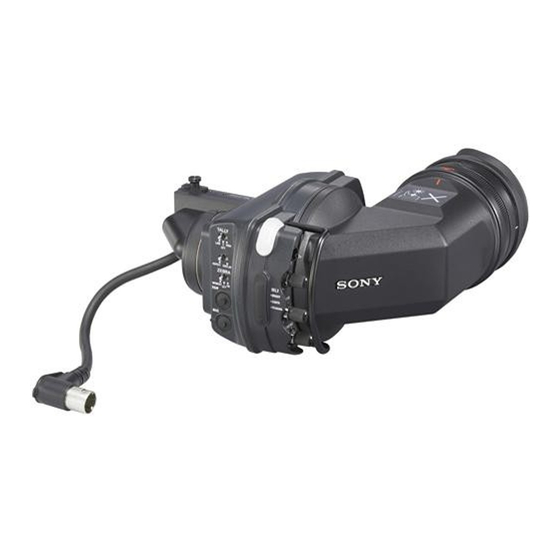
- Page 1 HD ELECTRONIC VIEWFINDER HDVF-C30WR MAINTENANCE MANUAL 1st Edition Serial No. 10001 and Higher...
- Page 2 électrique, d’incendie ou de blessure n’effectuer que les réparations indiquées dans le mode d’emploi à moins d’être qualifi é pour en effectuer d’autres. Pour toute réparation faire appel à une personne compétente uniquement. HDVF-C30WR...
-
Page 3: Table Of Contents
1-12. Notes on Repair Parts ..........1-20 (E) 1-13. Lead-free Solder ............1-20 (E) 1-14. Recommended Replacement Parts ......1-21 (E) 1-15. Viewfi nder Rotating Torque Adjustment ....1-22 (E) 1-16. When Rotation of Viewfi nder Becomes Diffi cult ...1-24 (E) 1 (E) HDVF-C30WR... -
Page 5: Manual Structure
Manual Structure Purpose of this manual This manual is the maintenance manual for Electronic Viewfi nder HDVF-C30WR. This manual describes the information items necessary when the unit is supplied and installed, items that premise the service based on the components parts such as main parts replacement, schematic diagrams, board layouts and spare parts lists, assuming use of system and service engineers. -
Page 7: Service Overview
HDW-730 : 10001 to 10053 If modifi cation of HD camcorder is needed, contact your local Sony Sales Offi ce/Service Center. 1-2. Check Item after Completing Maintenance When maintenance work is completed, check that the [SEL] (SEL1/SEL2 selector) switch is set to the SEL1 position (lower position). -
Page 8: Circuit Description
The selector switch operates in linkage with the installation of a VF tube. 1-4-5. SW-1436 Board The SW-1436 board mounts a selector switch of tally, zebra, marker, B&W, and MAG functions. The obtained information is sent to the PR-312 board. 1-2 (E) HDVF-C30WR... -
Page 9: Board
0.7 V p-p Zo = 75 Z Pb VIDEO 0.7 V p-p Zo = 75 Z Pr VIDEO No connection R TALLY ON : 5 V, OFF : GND No connection UNREG GND GND for UNREG UNREG DC 10.5 V to 17 V 1-3 (E) HDVF-C30WR... -
Page 10: Board
OFF: Selectable from among the 5 sections. ON: Fixed as the center section. In this case, the display automatically returns to normal about 5 seconds after the [MAG] button is pressed. S1-5 Enable the color-peaking function by default (Continued to next page) 1-4 (E) HDVF-C30WR... - Page 11 . Only one of S3-1 to S3-8 must be set to ON. Do not set two or more switches to ON or set all switches to OFF. . Set S3-7 to ON when replacing the LCD module. 1-5 (E) HDVF-C30WR...
- Page 12 SEL2 position. CONTRAST adjustment This adjustment is enabled by setting of the [SEL] (SEL1/SEL2 selector) PEAKING adjustment switch or that of the MAG button. For details, refer to Section 1-6-1, Switch S1-3. 1-6 (E) HDVF-C30WR...
-
Page 13: Board
The functions below do not operate in the energy saving mode. . Natural peaking . Color temperature conversion using lower-surface . Uniformity correction setting switches . S-log gamma return (S1-6 and S1-7 on the PR-312 board) . Panel gamma correction . Color area correction 1-7 (E) HDVF-C30WR... -
Page 14: Replacing The Main Parts
RE-257 board. 7. Remove the three screws. 8. Disconnect the connector (CN1) on the RE-257 board RE-257 board from the connector (CN2) on the PR-312 board. B2 x 3 PR-312 board Harness Tape (13x50) Tape (13x50) 1-8 (E) HDVF-C30WR... - Page 15 LE-476 board. 14. Disconnect the harness from the connector (CN1) on the LE-477 board. VPR heatsink 15. Remove the three screws, then remove the VPR heat- sink. B2 x 3 Harnesses LE-477 board B2 x 3 1-9 (E) HDVF-C30WR...
- Page 16 . Apply the tapes (13 x 50) to the portion as shown in the fi gure. Align the tape on the edge of Align the tape on the edge of the the RE-257 board. connector (CN7) on the PR-314 board. PR-312 board RE-257 board Tape (13x50) Tape (13x50) 1-10 (E) HDVF-C30WR...
-
Page 17: Replacing The Protection Glass And Glass Cushion
3. Peel off the protection glass from glass cushion to remove it. 4. Peel off the glass cushion from the front chassis and Front chassis wipe the attaching surface with alcohol. Protection glass Glass cushion Attaching surface 1-11 (E) HDVF-C30WR... - Page 18 6. Peel off the protection sheet form the surface of the Attaching surface glass cushion attached, and install the new protection glass. 7. To install, reverse the removal procedure. Precaution for installation Align the red marks when installing the VF tube. (Fig. 2 in Removal) Front chassis 1-12 (E) HDVF-C30WR...
-
Page 19: Replacing The Anti-Glare Sheet
Be extremely careful not to give any scar on the polar- izing fi lter surface of the viewfi nder lens unit during Align marks (red lines) the removal and installation procedures. Fixed ring VF tube VF lens unit Polarizing filter surface 1-13 (E) HDVF-C30WR... - Page 20 (B-M) and mirror assembly from the VF tube. M2 x 5 Ground Be extremely careful not to give any scar or stain on plate (B-M) the mirror surface during the removal and installation Mirror surface Mirror procedures. assembly VF tube 1-14 (E) HDVF-C30WR...
- Page 21 Align the alignment mark (red) of the VF lens unit with that of the alignment mark (red) of the fi xed ring when installing the VF lens unit, and insert the VF lens unit. Align marks (red lines) VF lens unit VF tube 1-15 (E) HDVF-C30WR...
-
Page 22: When The Lcd Module Is Replaced
Check the voltage at the following TP terminal on the EX-908 board. TP No. TP name Voltage check +2.5 V DC 2.25 ?0.10 V +1.8 V DC 1.8 ?0.1 V +3.2 V DC 3.2 ?0.1 V _7 V DC _7.0 ?0.1 V +1.2 V DC +1.2 ?0.1 V 1-16 (E) HDVF-C30WR... -
Page 23: How To Measure Luminance
Konica Minolta Model LS-100 or equivalent (that must have already been calibrated before) Procedure 1. Remove the VF tube by pushing the release knob. (Refer to Section 1-7-2, step 1.) 2. Install the front chassis of the HDVF-C30WR in the camera. 3. Rotate the BRIGHT control and CONTR control fully clockwise (MAX) beforehand. -
Page 24: Rewriting The Pld Internal Data
1. The standard fi xture cable can be used. 2. The standard software (PLD Download Tool) can be used. . The PLD internal data is controlled in the Sony Database Server under the name Project fi le (E_xxx_xxx_xx_xx). . The printed circuit board is equipped with the standard connector (EPR connector) to write the PLD internal data. - Page 25 PLD Download Tool software is available. 1. Prepare the Project fi le. Download the Project fi le from the Sony Database Server. 2. Push the release knob and remove the VF tube. (Refer to Section 1-7-2, step 1.) 3.
-
Page 26: Notes On Repair Parts
Components marked ! are critical to safe operation. Therefore, specifi ed parts should be used in the case of replacement. 2. Standardization of Parts Some repair parts supplied by Sony differ from those used for the unit. These are because of parts commonality and improvement. 3. Stock of Parts Parts marked with “o”... -
Page 27: Recommended Replacement Parts
Replacement of the backlight only is not possible. Replace the entire LCD module. Part name Sonny part number Remarks Eye cap 3-776-341-01 Rubber part SW cover 3-676-244-03 Rubber part 3-776-614-01 Rubber part LCD module 1-804-912-11 Refer to Section 1-7-1. 1-21 (E) HDVF-C30WR... -
Page 28: Viewfi Nder Rotating Torque Adjustment
fi nder has decreased after years of usage. Fixtures Hexagon wrench (d = 1.5 mm) Rotating torque Adjustment Procedure 1. Remove the four screws and remove the cable guard. Connecting cable (VF) B2 x 5 B2 x 5 Cable guard 1-22 (E) HDVF-C30WR... - Page 29 Rotating clockwise: Increases the rotating torque Rotating counter-clockwise: Decreases the rotating torque Rotate the two adjustment screws by the same amount of angle. 3. When adjustment is completed, confi rm that the view- fi nder rotates smoothly. Arm chassis Adjustment screws 1-23 (E) HDVF-C30WR...
-
Page 30: When Rotation Of Viewfi Nder Becomes Diffi Cult
(with stopper) VF arm Screws (with stopper) assembly 4. Apply Sony grease to the portion “a” (at the two locations) of the VF arm assembly. Rotary bracket VF arm assembly Apply suffi cient amount Sony grease satisfying the requirement of step 5. -
Page 31: Spare Parts
Therefore, specifi ed parts should be used in the case of な部品です。したがって,交換する時は必ず指定 replacement. の部品を使ってください。 2. Standardization of Parts 2. 部品の共通化 Some repair parts supplied by Sony differ from those ソニーから供給する補修用部品は,セットに使われて used for the unit. These are because of parts common- いるものと異なることがあります。 ality and improvement. -
Page 32: Exploded Views
VF Lens Unit and VF Unit 2-2. Exploded Views Precision P2 x 10 Ball (2.5mm) Precision P2 x 10 Precision P2 x 10 Ball (2.5mm) Precision P2 x 10 HDVF-C30WR... - Page 33 3-776-622-02 s SCREW(M2),TAPPING 3-776-637-02 s RING(TUBE),BAYONET 3-789-424-01 s SHEET(UPPER),ANTI-GLARE 3-789-425-01 s SHEET(LOWER),ANTI-GLARE 4-139-384-01 s LABEL, SAULER LIGHT CAUTION 4-139-826-01 s PANEL, ELBOW SUB 4-145-339-01 s SHEET, ELBOW SUB 7-627-553-78 s SCREW,PRECISION +P 2X10 7-671-158-01 s BALL, STAINLESS (2.5 DIA) HDVF-C30WR...
- Page 34 4-140-521-02 s SHEET, LCD BACK 3-080-202-01 s SCREW (M2), LOCK ACE, P2 4-144-672-01 s MASK, 5-LED 3-729-076-01 s SCREW (+B) (2X3) 4-144-673-01 s MASK, 3-LED 4-139-822-02 s HOLDER , LCD 4-144-674-01 s SEAL (U), HEAT SINK 4-119-886-01 s TAPE (13X50) HDVF-C30WR...
- Page 35 3-776-605-02 s LABEL,VF 3-776-614-01 s CAP 3-776-617-01 s GLASS,PROTECTION 3-776-618-02 s GLASS,CUSHION 3-776-619-02 s KNOB,RELEASE 3-776-624-02 s GUARD,BAR 3-776-628-01 s PIN 3-776-629-01 s RING(CHASSIS),BAYONET 3-776-630-01 s CUSHION(VR),DROP PROTECTION 3-776-636-03 s SPRING,BAYONET 4-139-821-01 s PLATE, VR GROUND 4-139-980-01 s SPRING, COMPRESSION HDVF-C30WR...
- Page 36 4-144-993-01 s CUSHION, T-SW 7-627-553-38 s SCREW,PRECISION +P 7-627-556-58 s SCREW +P 2.6X5 7-682-247-09 s SCREW +K 3X6 7-682-548-09 s SCREW +B 3X8 7-683-239-08 s SCREW H3X5 7-683-412-05 s BOLT,HEXAGON SOCKET 2.6X6 7-688-002-02 s W 2.6, SMALL 7-621-772-20 s SCREW +B 2X5 HDVF-C30WR...
-
Page 37: Electrical Parts List
1-100-159-91 s CAP, CERAMIC 22MF B (SMD) 3216 1-125-777-81 s CAP, CHIP CERAMIC 0.1MF B 1005 1-164-850-81 s CAP, CHIP CERAMIC 10PF CH 1005 1-125-777-81 s CAP, CHIP CERAMIC 0.1MF B 1005 1-125-777-81 s CAP, CHIP CERAMIC 0.1MF B 1005 HDVF-C30WR... - Page 38 1-125-777-81 s CAP, CHIP CERAMIC 0.1MF B 1005 C306 1-125-777-81 s CAP, CHIP CERAMIC 0.1MF B 1005 C534 1-125-777-81 s CAP, CHIP CERAMIC 0.1MF B 1005 C307 1-125-777-81 s CAP, CHIP CERAMIC 0.1MF B 1005 C535 1-125-777-81 s CAP, CHIP CERAMIC 0.1MF B 1005 HDVF-C30WR...
- Page 39 1-414-864-21 s FERRITE, EMI (SMD) (1608) 8-729-929-27 s TRANSISTOR DTC114TE-TL FB307 1-414-864-21 s FERRITE, EMI (SMD) (1608) 8-729-929-27 s TRANSISTOR DTC114TE-TL FB308 1-414-864-21 s FERRITE, EMI (SMD) (1608) 8-729-929-27 s TRANSISTOR DTC114TE-TL FB309 1-481-196-21 o FERRITE, EMI (SMD) (3216) 8-729-928-82 s TRANSISTOR DTC144EE-TL HDVF-C30WR...
- Page 40 1-208-871-81 s RES, CHIP 220 (1005) R114 1-218-990-81 s CONDUCTOR, CHIP (1005) 1-208-911-81 s RES, CHIP 10K (1005) R115 1-208-887-81 s RES, CHIP 1.0K (1005) 1-208-911-81 s RES, CHIP 10K (1005) R116 1-208-887-81 s RES, CHIP 1.0K (1005) 2-10 HDVF-C30WR...
- Page 41 1-208-895-81 s RES, CHIP 2.2K (1005) R545 1-208-855-81 s RES, CHIP 47 (1005) R208 1-208-895-81 s RES, CHIP 2.2K (1005) R546 1-208-855-81 s RES, CHIP 47 (1005) R209 1-208-895-81 s RES, CHIP 2.2K (1005) R548 1-208-855-81 s RES, CHIP 47 (1005) 2-11 HDVF-C30WR...
- Page 42 1-234-371-21 s RES, NETWORK 47 (1005X4) RB529 1-234-371-21 s RES, NETWORK 47 (1005X4) RB530 1-234-371-21 s RES, NETWORK 47 (1005X4) RB531 1-234-371-21 s RES, NETWORK 47 (1005X4) RB532 1-234-371-21 s RES, NETWORK 47 (1005X4) RB533 1-234-371-21 s RES, NETWORK 47 (1005X4) 2-12 HDVF-C30WR...
- Page 43 1-112-300-91 s CAP, CERAMIC 4.7MF B (2012) 8-729-929-27 s TRANSISTOR DTC114TE-TL 1-125-827-91 s CAP, CHIP CERAMIC 1MF B 8-729-928-05 s TRANSISTOR 2SC4617TL-QR 8-729-928-82 s TRANSISTOR DTC144EE-TL 1-164-882-81 s CAP,CHIP CERAMIC 220PF CH 1005 8-729-928-28 s TRANSISTOR DTA144EE-TL 1-112-691-11 s CAP, CERAMIC 22MF R 3225 2-13 HDVF-C30WR...
- Page 44 R103 1-218-990-81 s CONDUCTOR, CHIP (1005) R104 1-208-907-81 s RES, CHIP 6.8K (1005) 1-218-990-81 s CONDUCTOR, CHIP (1005) R105 1-208-923-81 s RES, CHIP 33K (1005) 1-208-927-81 s RES, CHIP 47K (1005) R106 1-208-943-81 s RES, CHIP 220K (1005) 2-14 HDVF-C30WR...
- Page 45 A-1675-717-A s MOUNTED CIRCUIT BOARD, SW-1437 1-770-628-21 s PIN, CONNECTOR 11P 1-208-863-81 s RES, CHIP 100 (1005) 1-234-372-21 s RES, NETWORK 100 (1005X4) 1-234-372-21 s RES, NETWORK 100 (1005X4) 1-786-900-11 s SWITCH, DIP (8P) 1-786-520-11 s SWITCH, TACTILE 2-15 HDVF-C30WR...
- Page 46 1-165-989-91 s CAP, CERAMIC 10MF (2012) C101 1-125-777-81 s CAP, CHIP CERAMIC 0.1MF B 1005 C160 1-165-989-91 s CAP, CERAMIC 10MF (2012) C102 1-125-777-81 s CAP, CHIP CERAMIC 0.1MF B 1005 C161 1-165-989-91 s CAP, CERAMIC 10MF (2012) 2-16 HDVF-C30WR...
- Page 47 6-712-135-01 o IC R1173H001D-T1-F 1-208-887-81 s RES, CHIP 1.0K (1005) 6-712-135-01 o IC R1173H001D-T1-F 1-208-895-81 s RES, CHIP 2.2K (1005) 8-759-488-34 s IC TLV2221CDBV 1-208-939-81 s RES, CHIP 150K (1005) 6-707-529-01 s IC TPS61041DBVR 1-208-915-81 s RES, CHIP 15K (1005) 2-17 HDVF-C30WR...
- Page 48 1-208-863-81 s RES, CHIP 100 (1005) R115 1-208-863-81 s RES, CHIP 100 (1005) R116 1-208-863-81 s RES, CHIP 100 (1005) R117 1-208-863-81 s RES, CHIP 100 (1005) R118 1-220-870-81 s RES, CHIP 10 (1005) R119 1-208-911-81 s RES, CHIP 10K (1005) 2-18 HDVF-C30WR...
-
Page 49: Packing Materials & Supplied Accessories
1-238-293-11 s RES, VAR, CARBON 10K 1-225-813-21 s RES, ADJ, CERMET 50K 1-238-293-11 s RES, VAR, CARBON 10K 1-225-813-21 s RES, ADJ, CERMET 50K 1-238-293-11 s RES, VAR, CARBON 10K 1-225-813-21 s RES, ADJ, CERMET 50K 1-570-984-21 s SWITCH, TOGGLE 2-19 HDVF-C30WR... -
Page 51: Block Diagrams Overall
ASPECT UNREG UNREG MOS FET +3.2V-A +3.1V B&W LOW, HIGH POWER-OFF VOLTAGE DETECT IC1-IC4 Q2, Q4-Q11 _6.8V _6.8V +5V_VREF +3.1V DC/DC +1.2V PWRGD CONTROLLER _6.8V IC201 (1/2) +2.5V +2.5V +1.8V +1.8V +2.5V DC/DC +1.2V +1.2V CONTROLLER +1.8V Overall Block HDVF-C30WR... -
Page 53: Schematic Diagrams
Section 4 Schematic Diagrams Index Board name Page LE-476 LE-477 PR-312 RE-257 SW-1436 4-11 SW-1437 4-11 VPR-103 4-12 VR-328 4-16 Frame Wiring 4-16 HDVF-C30WR... - Page 55 U/C_TALLY BATT U/R1_TALLY YELLOW U/R2_TALLY X_TALLY UDZSUSTE-173.9B UDZSUSTE-173.9B UDZSUSTE-173.9B UDZSUSTE-173.9B UDZSUSTE-173.9B UDZSUSTE-173.9B CL-196HR-CD-T R_TALLY UDZSUSTE-173.9B UDZSUSTE-173.9B CL-196HR-CD-T R_TALLY UDZSUSTE-173.9B CL-165HR/YG-D-T G_TALLY GREEN CL-197TLY-CD-T BATT YELLOW X_TALLY UDZSUSTE-173.9B UDZSUSTE-173.9B CL-197TD2-CD-T SAVE LE-476 AMBER BOARD NO. 1-879-253-12 LE-477 BOARD NO. 1-879-254-12 HDVF-C30WR...
- Page 56 R138 1k 6.3V SW_ZEB_ON I_SW_ZEB_ON ZEB-ON O_SW_TALLY 2SC4177-T1L5 SW_TALLY_OUT R139 1k SW_BW B&W I_SW_BW R140 1k SW_MAG +3.1V-3 I_SW_MAG TALLY_OUT +3.1V-3 DTA144EE-TL R126 TALLY_IN R141 +3.1V-3 12 11 0.1uF R142 IC22 (2/5) CL-201HR-C-TSL 4.7uF NJU7034V-TE2 6.3V CC-C 2.5V Vref HDVF-C30WR...
- Page 57 C334 C335 C115 C101 C136 0.1uF 0.1uF 0.1uF TALLY_OUT 0.1uF 1000pF 6.3V +3.1V-3 +3.1V-3 +3.1V-2 CC-C C114 R189 0.1uF 22uF R175 R213 R214 6.3V 2.2k 4.7uF 6.3V R180 R176 CC-C PR-312 (1/2) IC22 (3/5) R177 NJU7034V-TE2 BOARD NO. 1-879-250-12 HDVF-C30WR...
- Page 58 O_CPU_RW RAM2_DQ[31] RAMAD1_6 RAMAD1_0 RAM2_A[0] OPEN O_RAM_AD[6] IO_CPU_DATA[12] IO_CPU_DATA[12] RB517 R537 CPU_CS_X O_CPU_CS_x RAM2_DQ[29] IO_RAM2_DQ[29] RAMAD1_0 O_RAM_AD[0] RAMAD1_1 RAM2_A[1] RAM2_DQ[25] IO_RAM2_DQ[25] SDRAMBANK1_1 SDRAMBANK1_1 RAM2_BA[1] O_RAM_BA[1] RAMAD1_11 RAM2_A[11] SDRAMCLK1 RAM2_CLK RAMAD1_3 RAM2_A[3] RAMAD1_6 RAM2_A[6] SDRAMCKE1 RAM2_CKE CPU-IF RB528 O_P_RST_PLL1_X O_P_RST_PLL2_X HDVF-C30WR...
- Page 59 IO_RAM1_DQ[26] IO_RAM1_DQ[8] IO_RAM1_DQ[26] B[4] O_D_B[4] R544 PACIFIC_H_ACT INIT_DONE INIT_DONE_DELAY IO_RAM1_DQ[20] M19 IO_RAM1_DQ[20] I_INIT_DONE_DELAY RB527 C501 IO_RAM1_DQ[22] M18 +3.1V-3 IO_RAM1_DQ[22] 1000pF B[8] O_D_B[8] B[7] O_D_B[7] B[9] O_D_B[9] C567 0.1uF B[3] O_D_B[3] IC503 (2/2) TC7SH14FU(T5RSOYJF) O_D_B PR-312 (2/2) BOARD NO. 1-879-250-12 HDVF-C30WR...
- Page 60 R3112N161A-TR-FA TC7SH08FU(T5RSOYJF) OUT2_U 0.01uF 10uF INV2 6.3V UDZSUSTE-172.7B 150uF 10uF 10uF 6.3V 1.2A(with DDR-SDRAM) 6.3V MBR0530T1 +1.8V 10uF +1.8V R202 C200 0.22uF 10uH 0.022uF SI4804BDY-T1 DTC114TE-TL Q201 1.0-0.9S Delay 0.0068uF DTC144EE-TL 1.6V RESET R127 R126 H_START_UP DTC114TE-TL DTC114TE-TL DTC114TE-TL HDVF-C30WR...
- Page 61 R108 R109 4.7uF R106 22uF 10uF 10uF 220k R107 R137 SHDN 220pF R133 R104 UDZSUSTE-177.5B 6.8k 100k 2SC4617TL-QR R136 RB050L-40TE25 2SC4617TL-QR DOWN_DET H_START_UP 1SS400TE-61 DTC114TE-TL DTC114TE-TL DTC114TE-TL DOWN_DET 0.6A +1.2V +1.2V SL14 UDZSUSTE-172.4B 10uF 6.3V RE-257 BOARD NO. 1-879-251-12 HDVF-C30WR...
- Page 63 DISP ZEB-MOM ZEB-ON HIGH B&W 1.5k TALLY_IN TALLY_OUT +3.1V-3 SW_ASSIGN 3.3k 12 11 SW_S2[0] SW_S2[1] 2SC4177-T1L5 SW_S2[2] 0.01uF SW_S2[3] SW_S2[4] SW_S2[5] SW_S2[6] SW_S2[7] 13 12 SW-1437 BOARD NO. 1-879-256-12 B&W MOMENT DISP ASPECT SW-1436 BOARD NO. 1-879-255-12 4-11 4-11 HDVF-C30WR...
- Page 64 CPU_ADRS_17 CPU_DATA[1] CPU_ADRS[1] CPU_DATA_1 CPU_ADRS_1 +3.1V CPU_DATA[8] CPU_ADRS[5] CPU_DATA_8 CPU_ADRS_5 CPU_DATA[4] CPU_ADRS[12] CPU_DATA_4 CPU_ADRS_12 CPU_DATA[3] CPU_ADRS[6] CPU_DATA_3 CPU_ADRS_6 TRST CPU_ADRS[9] XRESET XRESET CPU_ADRS_9 PF_TDI CPU_ADRS[10] CPU_ADRS_10 PF_TDO CPU_CS_X CPU_RW CPU_CS_X CPU_RW PF_TMS PF_TCK Hirose-angle-8p 10 9 CPU-IF 4-12 4-12 HDVF-C30WR...
- Page 65 PANEL_IN_G[0] IO49 IO81 PACI_IN_B[5] PANEL_IN_G[1] IO50 IO80 3.0V +3.1V +3.1V-CONT 4.7k 2.2uH 0.1uF 22uF 4.7k 6.3V TL431CPK-E2 +3.1V-CONT TLV2221CDBV 0V - 1.8V CONT 4.7k 0.157V - 1.1V 0.1uF 4.7k 22pF 1005 XRESET VPR-103 (1/2) BOARD NO. 1-879-252-12 4-13 4-13 HDVF-C30WR...
- Page 66 AA29 AE29 I_DE_H_OD VREF_4 B_DDR_2_DQ_13 B_DDR_2_DQ_29 AK23 AA27 AA31 AF32 R117 I_DE_V VREF_5 B_DDR_2_DQ_14 B_DDR_2_DQ_30 R140 AN28 AA28 AB31 AG32 PACI_IN_CLK R118 I_CLK_IF VREF_6 B_DDR_2_DQ_15 B_DDR_2_DQ_31 AH34 C102 R119 VREF_7 O_DDR_2_CLK0 O_DDR_2_CLK1 0.1uF AH33 VREF_8 O_DDR_2_CLK0_X O_DDR_2_CLK1_X 4-14 4-14 HDVF-C30WR...
- Page 67 C153 O_TA6_N O_TB6_N O_TC6_N O_TD6_N 10uF C159 C184 0.1uF AVDD_VA6 AGND_GA6 10uF O_TACLK_P O_TBCLK_P O_TCCLK_P O_TDCLK_P L108 10uH O_TACLK_N O_TBCLK_N O_TCCLK_N O_TDCLK_N L115 10uH C154 10uF C160 10uF L109 10uH C155 10uF VPR-103 (2/2) BOARD NO. 1-879-252-12 4-15 4-15 HDVF-C30WR...
-
Page 68: Frame Wiring
SEL2 0.1uF 0.1uF 0.1uF 0.1uF 0.1uF 0.1uF SW-1436 VPR-103 +3.1V-3 TALLY_IN +3.1V-3 +3.1V-3 0.1uF 2SA1774TL-QR 0.1uF 100k LE-476 CPI-210-T SELECT PANEL LE-477 CL-201HR-C-TSL CL-201HR-C-TSL VR-328 2SC4177-T1L5 2SC4177-T1L5 SW-1437 CN501 CN500 EPR2 VR-328 BOARD NO. 1-879-257-12 Frame Wiring 4-16 4-16 HDVF-C30WR... - Page 69 *:B SIDE LE-477 LE-477 -A SIDE- -B SIDE- * A1 * A1 * A1 SUFFIX: -12 SUFFIX: -12 * A1 * A1 VR-328 VR-328 -B SIDE- -A SIDE- SUFFIX: -12 SUFFIX: -12 --------------------- VR-328 (1-879-257-12) --------------------- *:B SIDE * A1 HDVF-C30WR...
- Page 70 * C1 * C2 R106 * C2 R156 R408 * B2 R557 * A1 RB531 C102 * B1 C335 * B1 C553 * A1 * B1 IC201 * C1 * C2 R107 * C1 R157 R413 * B2 R558 RB532 HDVF-C30WR...
- Page 71 * A1 * B2 * A1 * A1 * A2 R126 * A2 * B2 * B1 * A2 * A1 * A2 R127 * A2 * B2 * A1 * A2 * A1 * A2 R128 * B2 HDVF-C30WR...
- Page 72 * A1 * B2 C110 * C2 C143 * C1 C176 * B1 * A1 R129 * B2 * A1 * A2 C111 * B2 C144 * C2 C177 * B2 * A2 * A2 R130 * B2 RB101 HDVF-C30WR...
- Page 74 Printed in Japan Sony Corporation HDVF-C30WR (SY) J, E 2009. 2 22 9-968-600-01 ©2009...