
Related Manuals for Sony HDVF-C30W


Summary of Contents for Sony HDVF-C30W
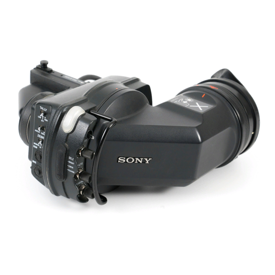
- Page 1 ELECTRONIC VIEWFINDER HDVF-C30W MAINTENANCE MANUAL 1st Edition Serial No. 10001 and Higher...
- Page 2 Ce manual est destiné uniquement aux personnes compétentes en charge de l’entretien. Afin de réduire les risques de décharge électrique, d’incendie ou de blessure n’effectuer que les réparations indiquées dans le mode d’emploi à moins d’être qualifié pour en effectuer d’autres. Pour toute réparation faire appel à une personne compétente uniquement. HDVF-C30W...
- Page 3 1-14. Notes on Repair Parts ................1-21 (E) 1-15. Unleaded Solder .................. 1-21 (E) 1-16. Recommended Replacement Parts ............1-22 (E) 1-17. Viewfinder Rotating Torque Adjustment ..........1-23 (E) 1-18. When Rotation of Viewfinder Becomes Difficult ......1-24 (E) 1 (E) HDVF-C30W...
- Page 4 Overall Block ......................4-1 5. Schematic Diagrams RE-208 ........................5-1 PR-267 ........................5-2 SW-1092 ......................... 5-5 VR-280 ........................5-5 Frame Wiring ......................5-6 6. Board Layouts PR-267 ........................6-1 RE-208 ........................6-2 SW-1092 ......................... 6-2 VR-280 ........................6-2 2 (E) HDVF-C30W...
- Page 5 Manual Structure Purpose of this manual This manual is the maintenance manual for Electronic Viewfinder HDVF-C30W. This manual describes the information items necessary when the unit is supplied and installed, items that premise the service based on the components parts such as main parts replacement, schematic diagrams, board layouts and spare parts lists, assuming use of system and service engineers.
-
Page 6: Overall Block
Section 4 Block Diagram Describes overall block diagram of this unit. Section 5 Schematic Diagrams Describes schematic diagrams for every circuit board and frame wiring . Section 6 Board Layouts Describes board layouts for every circuit board. 4 (E) HDVF-C30W... - Page 7 HDW-750CE : 40001 to 40036 HDW-730 : 10001 to 10053 If modification of HD camcorder is needed, contact your local Sony Sales Office/Service Center. 1-2. Check Item after Completing Maintenance When maintenance work is completed, check that the SEL1/SEL2 selector switch is set to the SEL1 position (lower position).
-
Page 8: Circuit Description
SEL switch. The VR-280 board contains the tally lamp UNREG GND GND for UNREG drive circuit that turns on or off the TALLY lamp in UNREG DC 10.5 V to 17 V accordance with the command supplied from the camera. 1-2 (E) HDVF-C30W... - Page 9 S1-3: OFF S1-3: ON SEL1/SEL2 switch MAG button SEL1 SEL2 (Magnified display) (Normal display) PEAKING control PEAKING adjustment variable resistor * : Refer to the Section 1-6-2. (Yes : Enabled, No : Disabled) (Continued to next page) 1-3 (E) HDVF-C30W...
- Page 10 Increases approx. 1500 K (becomes bluish) Color temperature does not change except by the above switch combinations. The screen display luminance decreases as a result of color temperature adjustment. Chromaticity diagram +1000 K +1500 K +500 K _500 K [6500 K] 1-4 (E) HDVF-C30W...
- Page 11 ON : Direction of scanning can be selected forcibly (The switch S2 on the VR-208 board is disbled.) S2-4 TEST SAW waveform output switch ON : Generates the TEST SAW waveform within viewfinder. Use the TEST SAW signal to check the video signal system using the EX-909 board. 1-5 (E) HDVF-C30W...
- Page 12 MAG button. For details, refer to Section 1-6-1, Switch S1-3. BRIGHTNESS They can be adjusted when adjustment the SEL1/SEL2 selector switch (on the side panel) is CONTRAST set to the SEL2 position. adjustment 1-6 (E) HDVF-C30W...
- Page 13 PR-267 board. (Refer to Section 1-8-1.) 11. Install the removed parts by reversing the steps 1 to 7 of removal. Precaution for installation Be sure to insert the connectors to the circuit board securely for sure connection of the connectors. 1-7 (E) HDVF-C30W...
- Page 14 5. Peel off the glass cushion from the front chassis and wipe the attaching surface of the glass cushion with Precaution for installation alcohol. Align the red marks when installing the viewfinder barrel. (Fig. 2) 1-8 (E) HDVF-C30W...
- Page 15 Be extremely careful not to give any scar on the polarizing filter surface of the viewfinder lens unit during the removal and installation procedures. Fixed rings Red lines Red lines Fixed ring Viewfinder barrel Viewfinder lens unit Polarizing filter surface 1-9 (E) HDVF-C30W...
- Page 16 Be extremely careful not to give any scar or stain on Side view Slot sheet (ring) the mirror surface during the removal and installation procedures. Tapping screws Bayonet rings M2 x 5 (TUBE) Mirror Mirror surface assembly Slot Viewfinder barrel 1-10 (E) HDVF-C30W...
- Page 17 5. Similarly, align the anti-glare sheet (Lower) with the sides “c” and “f” and attach it to the viewfinder barrel. Anti-glare sheet (Upper) Protection sheet 6. Install the removed parts by reversing the steps 1 and 2 of removal. 1-11 (E) HDVF-C30W...
- Page 18 (Refer to Section 1-7-2, setp 1.) Instruments 2. Perform steps 1 to 3 of “1-7-1. Replacing the LCD Panel.” Name of the fixture/ Sony part Application 3. Remove the RE-208 board. measuring instrument number (Refer to Section 1-7-2, step 6.)
- Page 19 . EX-909 board Sony part number : A-8346-442-A The EX-909 board can be used by connecting either to the . Connecting cable Sony part number : 1-827-086-21 CN5 connector or the CN6 connector on the PR-267 board. . RE-208 EX unit...
- Page 20 8. Turn on the power of the camera and select the color bar signal as the output signal from the camera (Set the OUTPUT/DCC switch on the camera side panel to the BARS position). 9. Set the switch S2-4 of the PR-267 board to ON. 1-14 (E) HDVF-C30W...
- Page 21 *1 : This pulse appears at the SP1 terminal during the normal display and at the SP4 terminal during the inverted display once every 1H period. *2 : Data is fetched every two pixels and are assigned to the upper- and lower-side drivers in the LCD circuit. 1-15 (E) HDVF-C30W...
- Page 22 *3 : 0- to 7-bit signal of Rch, Gch, and Bch signals that are sent to LCD. TP2 to TP9 : 0- to 7-bit Rch signal TP10 to TP17 : 0- to 7-bit Gch signal TP18 to TP25 : 0- to 7-bit Bch signal 1-16 (E) HDVF-C30W...
- Page 23 The alphanumeric in parentheses ( ) of Ref.No. indicates IC17 the addresses on the board. (1) Pin-6/IC7 (B-1) PR-267 (B side) 1.9 V 1.02 V Y VIDEO (2) Pin-6/IC5 (B-1) 1.5 V 0.9 V PB VIDEO 1-17 (E) HDVF-C30W...
- Page 24 (Amplitude of 3 to 5 V) (3) Pin-15/IC11, IC12 (C-3), IC13 (B-3) . Clock pulse for video signal : 37 MHz (4) Voltage . Collector/Q3 (B-1) : DC 3.0 ± 0.1 V . Collector/Q16 (A-1) : DC 2.5 ± 0.1 V 1-18 (E) HDVF-C30W...
- Page 25 Procedure 1. Remove the viewfinder barrel by pushing the RE- Connecting harness : 1 piece LEASE knob. (Refer to Section 1-7-2, step 2.) 2. Install the front chassis of the HDVF-C30W in the Connecting diagram camera. Connecting harness 3. Rotate the BRIGHT control and CONTR control fully clockwise (MAX) beforehand.
- Page 26 (EPR) system when rewriting the internal data. The RE-208 board contains the high-voltage DC/AC If the PLD needs to be upgraded, contact your Sony Sales inverter transformer (T101). Office/Service Center. Repair the unit with extreme care not to touch the high-...
- Page 27 1. Prepare the Project file. 2. Standardization of Parts Download the Project file from the Sony Database Some repair parts supplied by Sony differ from those Server. used for the unit. These are because of parts common- ality and improvement.
- Page 28 Replacement of the backlight only is not possible. Replace the entire LCD panel. Part name Sonny part number Remarks Eye cap 3-776-341-01 Rubber part MC holder 3-623-709-01 Rubber part SW cover 3-676-244-03 Rubber part 3-776-614-01 Rubber part Backlight 1-804-892-11 Replace the entire LCD panel. (Refer to Section 1-7-1.) 1-22 (E) HDVF-C30W...
- Page 29 Arm chassis Adjustment screws Adjustment Procedure 1. Remove the four screws and remove the cable guard. 3. When adjustment is completed, confirm that the viewfinder rotates smoothly. Connecting cable (VF) B2 x 5 B2 x 5 Cable guard 1-23 (E) HDVF-C30W...
- Page 30 1-18. When Rotation of Viewfinder 4. Apply Sony grease to the portion “a” (at the two Becomes Difficult locations) of the arm assembly. When viewfinder is rotated very frequently, there can be a Apply sufficient amount Sony grease satisfying the case that rotation of viewfinder becomes difficult or that requirement of step 5.
-
Page 31: Notes On Repair Parts
Therefore, specified parts should be used in the case of replacement. 2. Standardization of Parts Some repair parts supplied by Sony differ from those used for the unit. These are because of parts common- ality and improvement. Parts list has the present standardized repair parts. -
Page 32: Exploded Views
7-627-553-78 s SCREW, PRECISION +P 2X10 3-692-136-03 o FIXED RING 7-671-112-11 s STEEL BALL (2.5MM) 3-723-073-01 o CUSHION, MIRROR 3-726-904-01 o RING (MT), O (CR) 3-742-038-01 o NUT (2), PLATE (SST) 3-742-052-03 o HOLDER, EYE CUP 3-742-053-02 o RING HDVF-C30W... - Page 33 2-277-466-01 s SPRING, COMPRESSION (STEEL) 3-776-604-02 s SHEET, INSULATING 2-640-315-01 o SCREW(M2X5), SMALL (STEEL) 3-685-104-01 s NUT(M6), CONTROL (STEEL) 7-628-253-00 s SCREW +PS 2X4 3-729-061-01 s SCREW (M2X4.5) (TYPE 1) (STEEL) 3-776-605-02 s LABEL, VF 3-776-613-01 s SPRING, COMPRESSION 3-776-614-01 s CAP HDVF-C30W...
- Page 34 3-679-695-01 o COVER, TALLY 3-710-008-02 s HOUSING, STOPPER 7-682-548-09 s SCREW +B 3X8 3-719-381-21 s SCREW +P M2X6 (EP-FE/ZNBK)LOCK 7-683-239-08 s SET-SCREW, HEX 3X5 ST 7-683-412-05 s BOLT, HEXAGON SOCKET 2.6X6 (ST) 3-729-007-01 o PLATE, ORNAMENTAL, TOGGLE SWITCH 7-688-002-02 s WASHER (2.6) HDVF-C30W...
-
Page 35: Electrical Parts List
1-125-777-11 s CAPACITOR,CERAMIC 0.1MF/10V C113 1-127-760-11 s CAPACITOR,CERAMIC 4.7MF/6.3V C114 1-100-159-91 s CAP, CERAMIC 22MF B (SMD) 3216 1-100-159-91 s CAP, CERAMIC 22MF B (SMD) 3216 C115 1-125-777-11 s CAPACITOR,CERAMIC 0.1MF/10V 1-125-777-11 s CAPACITOR,CERAMIC 0.1MF/10V C116 1-164-878-11 s CAPACITOR, CHIP CERAMIC 150PF HDVF-C30W... - Page 36 1-208-711-11 s RESISTOR,CHIP 15K 1/16W (1005) 1-233-996-11 s FILTER,LOW PASS 1-208-695-11 s RESISTOR,CHIP 3.3K 1/16W(1005) 1-208-687-11 s RESISTOR,CHIP 1.5K 1/16W (1005 8-759-447-19 s IC AD8041AR 8-759-371-78 s IC LT1431CS8-E1 1-208-695-11 s RESISTOR,CHIP 3.3K 1/16W(1005) 8-759-447-19 s IC AD8041AR 1-208-935-11 s RESISTOR,CHIP 100K (1005) HDVF-C30W...
- Page 37 1-208-927-11 s RESISTOR,CHIP 47K 1/16W(1005) 1-208-695-11 s RESISTOR,CHIP 3.3K 1/16W(1005) R135 1-208-683-11 s RESISTOR,CHIP 1K 1/16W (1005) 1-208-707-11 s RESISTOR,CHIP 10K 1/16W (1005) R136 1-208-683-11 s RESISTOR,CHIP 1K 1/16W (1005) 1-208-707-11 s RESISTOR,CHIP 10K 1/16W (1005) R137 1-208-683-11 s RESISTOR,CHIP 1K 1/16W (1005) HDVF-C30W...
- Page 38 1-208-711-11 s RESISTOR,CHIP 15K 1/16W (1005) R258 1-218-939-11 s RESISTOR,CHIP 68 1/16W (1005) R195 1-208-691-11 s RESISTOR,CHIP 2.2K 1/16W(1005) R259 1-218-939-11 s RESISTOR,CHIP 68 1/16W (1005) R196 1-208-711-11 s RESISTOR,CHIP 15K 1/16W (1005) R260 1-218-939-11 s RESISTOR,CHIP 68 1/16W (1005) HDVF-C30W...
- Page 39 1-218-939-11 s RESISTOR,CHIP 68 1/16W (1005) R319 1-208-707-11 s RESISTOR,CHIP 10K 1/16W (1005) R320 1-208-707-11 s RESISTOR,CHIP 10K 1/16W (1005) R321 1-208-707-11 s RESISTOR,CHIP 10K 1/16W (1005) R322 1-218-945-11 s RESISTOR,CHIP 220 1/16W(1005) R323 1-218-945-11 s RESISTOR,CHIP 220 1/16W(1005) HDVF-C30W...
- Page 40 8-719-991-00 s DIODE DAP222 8-719-989-93 s DIODE SB01-15CP 1-208-707-11 s RESISTOR,CHIP 10K 1/16W (1005) 1-218-941-11 s RESISTOR,CHIP 100 1/16W (1005) 8-719-938-75 s DIODE SB05-05CP (RECTI) 1-208-675-11 s RESISTOR,CHIP 470 1/16W (1005) 8-719-938-75 s DIODE SB05-05CP (RECTI) 1-208-703-11 s RESISTOR,CHIP 6.8K 1/16W(1005) 2-10 HDVF-C30W...
- Page 41 1-208-931-11 s RESISTOR,CHIP 68K (1005) R109 1-208-719-11 s RESISTOR,CHIP 33K 1/16W (1005) R110 1-208-947-11 s RESISTOR,CHIP 330K 1/16W(1005) R111 1-208-707-11 s RESISTOR,CHIP 10K 1/16W (1005) R112 1-218-941-11 s RESISTOR,CHIP 100 1/16W (1005) R113 1-208-683-11 s RESISTOR,CHIP 1K 1/16W (1005) 2-11 HDVF-C30W...
- Page 42 1-218-945-11 s RESISTOR,CHIP 220 1/16W(1005) 1-771-483-61 s SWITCH,PUSH (1 KEY) 1-208-671-11 s RESISTOR,CHIP 330 1/16W (1005) 1-208-695-11 s RESISTOR,CHIP 3.3K 1/16W(1005) 1-762-489-11 s SWITCH, TOGGLE 1-762-020-11 s SWITCH, TOGGLE 1-762-019-11 s SWITCH, TOGGLE 1-786-520-11 s SWITCH, TACTILE 1-786-520-11 s SWITCH, TACTILE 2-12 HDVF-C30W...
-
Page 43: Packing Materials And Supplied Accessories List
(TO CN3/PR-267 BOARD & CN1/SW-1092 BOARD) J-6029-140-B o PATTERN BOX, PTB-500 20pcs 1-695-215-11 o TERMINAL,SOLDERLESS J-7120-140-A o PLD DOWNLOAD TOOL 1-827-086-21 s CORD, CONNECTION (VF) HN003 ------------ HARNESS (VR) (TO CN7/PR-267 BOARD & CN1/VR-280 BOARD) 24pcs 1-695-215-11 o TERMINAL,SOLDERLESS 2-13 HDVF-C30W... - Page 45 In addition, for semiconductors with ID Nos., refer to the separate CD-ROM titled “Semiconductor Pin Assignments” (Sony Part No. 9-968-546-xx) that allows searching for parts by semiconductor type or ID No. The semiconductors in the manual or on the CD-ROM are listed by equivalent types.
- Page 46 — PWRCON BUFF REF IN/OUT 8-BIT INPUT HALF 3-1, FLASH 28-24 PARALLEL DB0 - DB7 PORT CLAMP CLAMPIN AINP AINN GAIN GAIN CORRECTION LOGIC BANDGAP REFERENCE OUTPUT BUFFERS 3 - 12 D0 - D9 REFSENSE 0.5 V AGND PWRCON HDVF-C30W...
- Page 47 SW BLANK UNDERVOLTAGE LOCKOUT THERMAL SHUTDOWN SHDN 1.26 V I R 1.25 V MODE CONTROL PROG I VC SLOPE CCLAMP SENSE FAULT MULTI-MODE ICIO1 < 125uA (ICIO1 + ICIO2) PWM PERIOD DIMMING BLOCK GAIN FAULT ICIO2 < 125uA DIO1 DIO2 HDVF-C30W...
- Page 49 PROTECT POWER_OFF +20V_IN -7.2V_OUT FRAME_P 10.5V 10.5V 10.5V_IN 19.5V +20V_OUT CONTRAST -6.6V -7.2V FRAME_P IC101 10.5V_OUT Q13 to 15 D5 to 7 CONTRAST IC102 CCFL +CCFL ROYER OSC BACK LIGHT -CCFL Q106 to 108 CONT-GND1, 2 T101 Overall Block HDVF-C30W...
-
Page 51: Re-208
100k Q102 Q106 R104 R105 R106 DTC144EE-TL 100k SI4450DY-T1 C109 C114 C101 0.1uF 0.1uF C115 0.022uF 0.1uF CC-C R112 IC101 (1/2) NJU7022M-TE2 C110 R114 C105 0.001uF R115 0.047uF 4.7k CC-C CC-C RE-208 BOARD NO. 1-688-279-12 LOT NO. 331- CXA-088_RE-208_012_1 HDVF-C30W... -
Page 52: Pr-267
GND GND ZEB-MOM R138 ZEB-ON +2.5V IC16-315 R139 B&W R140 2SC4177-T1L5 +3.1V-3 IC16-227 +3.1V IC22 (2/4) TALLY_OUT 2.2uH NJU7034V-TE2 +3.1V-3 DTA144EE-TL TALLY_IN 2SA1213Y-TE12L R141 C137 +3.1V-3 22uF 22uF 0.1uF 6.3V 6.3V 10pF 0.1uF R142 2SC4177-T1L5 CL-200HR-C-TSL 4.7uF 6.3V CC-C HDVF-C30W... - Page 53 VOFF C101 22uF C103 -7.2V 0.1uF 6.3V 0.022uF 0.1uF +20V C114 C136 22uF C115 6.3V 0.1uF 0.001uF 6.3V VCCO VLCO CC-C VCCO VLCO VCCO VLCO +3.1V-3 VCCO VLCO VCCO VLCO PR-267 (1/2) BOARD NO. 1-688-278-11 LOT NO. 331- CXA-088_PR-267_011_1 HDVF-C30W...
- Page 54 +3.1V-3 BUS3 IC16-315 R298 R291 3.3k 150k RESET +3.1V-3 R296 C205 R281 R282 0.1uF C207 0.1uF R297 +3.1V-3 DCLK DATA +3.1V-3 nCASC R269 R268 nINIT_CONF VCCSEL IC26 VPPSEL EPC2LC20-TP R283 PR-267 (2/2) BOARD NO. 1-688-278-11 LOT NO. 331- CXA-088_PR-267_011_2 HDVF-C30W...
-
Page 55: Sw-1092
P-CONT TALLY_OUT +3.1V-3 4.7k +3.1V-3 SEL2 4.7k 4.7k 3.3k +3.1V-3 TALLY_IN +3.1V-3 2SC4177-T1L5 0.01uF SELECT CL-200HR-C-TSL CL-200HR-C-TSL B&W MOMENT DISP ASPECT 2SC4177-T1L5 2SC4177-T1L5 SW-1092 VR-280 BOARD NO. 1-688-280-11 BOARD NO. 1-688-281-11 LOT NO. 331- LOT NO. 331- CXA-088_SW-1092_011_1 CXA-088_VR-280_011_1 HDVF-C30W... -
Page 56: Frame Wiring
FRAME_P FRAME_P CCFL-GND CCFL-GND +10.5V_OUT +10.5V_IN CONTRASST CONTRASST VOFF VOFF VCCO VCCO VCCO VLCO VCCO VCCO VCCO VLCO VCCO VCCO VCCO VLCO VCCO VCCO VCCO VLCO VCCO VCCO VCCO VLCO +CCFL BACK LIGHT -CCFL Frame Wiring LOT NO. 331- HDVF-C30W... - Page 57 R100 R187 R277 R101 R188 R278 R102 R189 R279 R103 R190 R280 R104 R191 R281 R105 R192 R282 CL10 R106 R193 R283 R107 R194 R284 R108 R195 R285 R109 R196 R286 PR-267 R110 R197 R287 -B SIDE- SUFFIX: -11 HDVF-C30W...
- Page 58 R111 R112 R113 Q101 R114 Q102 R115 Q106 D101 Q107 D102 Q108 T101 IC101 *A2 IC102 *A3 C101 C102 C103 C104 L101 C105 L102 C106 C107 VR-280 VR-280 -A SIDE- -B SIDE- C108 C109 SUFFIX: -11 SUFFIX: -11 C110 HDVF-C30W...
- Page 60 Printed in Japan Sony Corporation HDVF-C30W (SY) J, E 2003. 4 16 B&P Company 9-968-009-01 ©2003...