Advertisement
Quick Links
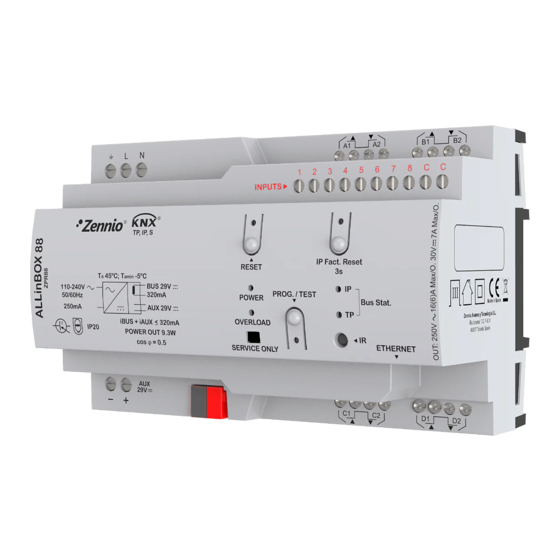
Multifunction device with KNX power supply, KNX-IP Interface, 8 outputs, 8 inputs and logical module
ZPR88
FEATURES
•
320mA KNX power supply with 29VDC auxiliary output.
•
110-240VAC 50/60Hz power input.
•
KNX system voltage supply and monitorization.
•
Short-circuit and overvoltage protection.
•
Reset button and overload status LED.
•
KNXnet/IP tunneling protocol (up to 5 connections).
•
Maximum APDU length of 254bytes.
•
Ethernet 10/100 BaseT IP with RJ45 socket.
•
2 different configurable blocks: shutter channels (up to 4), individual
outputs (up to 8) and 2/4-pipe fan coil controls (up to 1).
•
Outputs suitable for capacitive loads, maximum 140µF.
•
Manual output operation through remote control.
•
8 analog/digital inputs.
•
Climate control for up to 4 rooms.
•
Output timing.
•
20 logic functions.
•
Total data saving on KNX bus failure.
•
Integrated KNX BCU.
•
Dimensions 67 x 90 x 140 mm (8 DIN units).
•
DIN rail mounting (EN 50022), with fixing clamp.
•
Possibility of connecting different phases in adjacent channels.
•
Conformity with the CE directives (CE-mark on the right side).
1. Main power supply
6. IP factory reset button
11. Auxiliary power output
16. Outputs
PROGRAMMING/TEST BUTTON: short press to set programming mode. If this button is held while providing main power supply to the device, it enters
the safe mode. If this button is held for more than 3 seconds, the device enters the test mode.
PROGRAMMING/TEST LED: programming mode indicator (red). When the device enters the safe mode, it blinks (red) every half second. The manual
mode is indicated by the green color. During the start-up (reset or after providing main power supply) and if the device is not in safe mode, it starts a
blue blinking sequence.
POWER SUPPLY STATUS LED: it indicates the status of the power supply (green color: the device is working properly; off LED: power supply failure;
green blinking: short-circuit on KNX bus and/or auxiliary power output).
OVERLOAD STATUS LED: it indicates an overload on the KNX line or on the auxiliary power output (red blinking: cut-off due to overload/short circuit
on the KNX bus and/or the auxiliary power output*; red color: overload on bus and/or auxiliary power output line *).
*Reduce the load on the bus and/or the auxiliary power output lines until its total consumption does not exceed the maximum current specified.
KNX BUS LED: it indicates that the device is powering up the KNX bus (green color).
ETHERNET LED: it indicates that the device is connected to Ethernet and has an IP address assigned (green color).
RESET INDICATOR LED: it indicates that a reset of the KNX system has been performed by using the corresponding reset button (red blinking). To
reset the bus power supply, the Reset button should be pressed (it is recommended to hold it for at least 5 seconds to verify the reset of all the devices
in the line). The reset LED will blink slightly in red while the Reset button is pressed.
IP FACTORY RESET INDICATOR LED: it indicates that the device has just performed an IP factory reset (red color). To reset the KNX IP Interface,
the IP Factory reset button must be pressed for at least 3 seconds.
MANUAL CONTROL: In order to perform manual control of the device, an IR remote control is necessary (Ref. 9900024) not included with the ALLinBOX
88. When the device is in Test On mode, the manual control can be done by pressing the corresponding buttons on the IR remote control (please, be
sure that the remote IR emitter is pointing to the IR input of ALLinBOX 88).
© Zennio Avance y Tecnología S.L.
2. Overload status LED
7. IP factory reset LED
12. KNX connector
17. IR input
Edition 1
1
2
11
3. Power supply status
LED
8. Ethernet LED
13. Programming/Test
14. Programming/Test
button
18. Ethernet connector
Further information
ALLinBOX 88
TECHNICAL DOCUMENTATION
8
3
4
6
7
5
12
13 14
15
4. Reset button
5. Reset status LED
9. KNX bus LED
10. Analog/digital inputs
LED
19. Remote control (not included, ref. 9900024)
www.zennio.com
10
16
9
18
17
16
19
15. Fixing clamp
Page 1/4
Advertisement

Related Manuals for Zennio ALLinBOX 88

Summary of Contents for Zennio ALLinBOX 88
- Page 1 88. When the device is in Test On mode, the manual control can be done by pressing the corresponding buttons on the IR remote control (please, be sure that the remote IR emitter is pointing to the IR input of ALLinBOX 88).
- Page 2 Mechanical lifetime (min. cycles) 3 000 000 Electrical lifetime (min. cycles) 100000 @ 8A / 25000 @ 16A (VAC) ¹ Lifetime values could change depending on the load type. © Zennio Avance y Tecnología S.L. Edition 1 Further information www.zennio.com Page 2/4...
- Page 3 * In case of using ZN1IO-DETEC-P sensor, its micro switch number 2 must be in Type B position. ** Zennio temperature probe or any NTC with known resistance values at three points in the range [-55, 150ºC]. © Zennio Avance y Tecnología S.L.
- Page 4 • The facility must be equipped with a device that ensures the omnipolar sectioning. Installation of a 10A mini-circuit-breaker is recommended. To prevent accidents, it must remain open in case of manipulation of the device. • The device has a short-circuit protection fuse that, in case of activation, should only be rearmed or replaced by the Zennio technical service.