Panasonic AK-HRP1000G Operating Manual
Remote operation panel
Hide thumbs
Also See for AK-HRP1000G:
- Operating instructions manual (144 pages) ,
- Operating manual (37 pages) ,
- Operation manual (34 pages)
Table of Contents
Advertisement
Quick Links
Operating Guide
Read this document when using the AK-HRP1000G Remote Operation Panel in
conjunction with AW-UE100 4K Integrated Camera.
For details of operating Remote Operation Panel AK-HRP1000G, please
visit the Panasonic website (https://pro-av.panasonic.net/manual/en/index.
html), and refer to the Operating Instructions (HTML or PDF).
W0321AM0 -PS
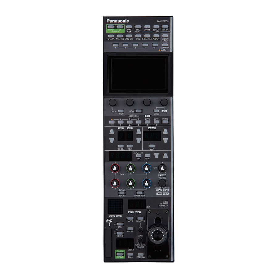
Remote Operation Panel
AK-HRP1000G
Model No.
ENGLISH
DVQP2489ZA
Advertisement
Table of Contents

Related Manuals for Panasonic AK-HRP1000G


Summary of Contents for Panasonic AK-HRP1000G
- Page 1 Operating Guide Remote Operation Panel AK-HRP1000G Model No. Read this document when using the AK-HRP1000G Remote Operation Panel in conjunction with AW-UE100 4K Integrated Camera. For details of operating Remote Operation Panel AK-HRP1000G, please visit the Panasonic website (https://pro-av.panasonic.net/manual/en/index.
-
Page 2: Table Of Contents
Table of Contents Connecting the Unit to AW-UE100 Cameras Connection Example Connections Compatible Functions List ROP Menu (during AW-UE100 connection) ROP Menu List 01 SHUTTER SPEED 02 PEDESTAL 03 CHROMA 04 GAIN 05 WHITE BALANCE 06 GAMMA 07 BLACK GAMMA 08 KNEE 09 WHITE CLIP 10 DRS... -
Page 3: Connecting The Unit To Aw-Ue100 Cameras
* Prepare a cable that is in accordance with the following serial connection cable specifications. Switching hub PoE injector with PoE support LAN cable (straight cable) Serial connection cable specifications AK-HRP1000G <CCU> connector side AW-UE100 <RS-422> connector side (RJ-45) - 3 -... -
Page 4: Connections
Connecting the Unit to AW-UE100 Cameras Connections Set the connection setting to “Serial(AW5)” or “LAN(AW5)” in the [CONNECT SETTING] menu. When connecting, observe the following points. Serial connection Use a dedicated cable to connect the <CCU> connector of this unit to the <RS-422> connector of the AW-UE100. Use a PoE injector for the power supply. -
Page 5: Compatible Functions List
Connecting the Unit to AW-UE100 Cameras Compatible Functions List When the unit is used in conjunction with an AW-UE100 4K Integrated Camera, there will be functions that are limited or disabled for some of the unit's buttons, dials, and other controls. Be sure to refer to the following table. Front panel 1 Front panel 2 Front panel 3... - Page 6 Connecting the Unit to AW-UE100 Cameras ✓ : Enabled Number Part name Remarks ×: Disabled ✓ [ASSIGN STATUS] button ✓ Buttons 1 to 5 (CONTROL/MODE) Functions only when the following functions have been assigned. CONTROL(MENU)1 to 5 SHUT U.CHRM GAIN GAMMA B.GAM KNEE...
- Page 7 Connecting the Unit to AW-UE100 Cameras ✓ : Enabled Number Part name Remarks ×: Disabled ✓ [SHUTTER] display “ELC” is displayed on the [SHUTTER] display when ELC is selected. ✓ [(SHUTTER) ON] button Front panel 6 ✓ [(SHUTTER) SYNC] button ✓...
- Page 8 Connecting the Unit to AW-UE100 Cameras ✓ : Enabled Number Part name Remarks ×: Disabled ✓ Camera number/tally display ✓ [ALM] indicator [OPT] indicator × ✓ [PANEL ACTIVE] button Front panel 9 [CALL] button × ✓ [PREVIEW] button ✓ Memory card slot ✓...
-
Page 9: Rop Menu (During Aw-Ue100 Connection)
ROP Menu (during AW-UE100 connection) ROP Menu (during AW-UE100 connection) ROP Menu List When an AW-UE100 4K Integrated Camera is connected, the ROP menu will be as follows. NOTE To perform menu operations, upgrade the system version of the unit to V5.00-00-0.00 or later. For details on menu operations, refer to the following sections in the Operating Instructions. - Page 10 ROP Menu (during AW-UE100 connection) “MASTER DTL” (see page 25) MASTER DTL CORING “CORING” (see page 25) V DTL LEVEL “V DTL LEVEL” (see page 25) FREQ “FREQ” (see page 25) “LEVEL DEPEND.” (see page 25) LEVEL DEPEND. “KNEE APE.LEVEL” (see page 25) 11 DETAIL KNEE APE.LEVEL “GAIN(+)”...
- Page 11 ROP Menu (during AW-UE100 connection) “TYPE” (see page 28) TYPE ADAPTIVE MATRIX “ADAPTIVE MATRIX” (see page 28) COLOR CORRECT “COLOR CORRECT” (see page 28) “SAT” (see page 28) “PHASE” (see page 28) PHASE “SAT B_Mg” (see page 28) SAT B_Mg “PHASE B_Mg”...
- Page 12 ROP Menu (during AW-UE100 connection) “FOCUS MODE” (see page 32) FOCUS MODE FOCUS SPEED “FOCUS SPEED” (see page 32) FOCUS “FOCUS” (see page 32) ZOOM TELE “ZOOM TELE” (see page 32) “ZOOM SPEED” (see page 32) 16 LENS CONTROL ZOOM SPEED “ZOOM WIDE”...
- Page 13 ROP Menu (during AW-UE100 connection) CONTROL(MENU)1 Refer to the following section in the Operating Instructions. “34 ROP SETTING” CONTROL(MENU)2 CONTROL(MENU)3 CONTROL(MENU)4 CONTROL(MENU)5 B.GAMMA SW MODE(ON/OFF)1 MODE(ON/OFF)2 MODE(ON/OFF)3 MODE(ON/OFF)4 MODE(ON/OFF)5 ECC BTN CTRL ASSIGN BUTTON USER ASSIGN IRIS LEV MODE CAM SEL DTL VOL SKIN DTL SW LCD BRIGHT...
- Page 14 ROP Menu (during AW-UE100 connection) ROP IP ADDRESS Refer to the following section in the Operating Instructions. “36 ROP IP SETTING” ROP PORT UPLOAD ROP SUBNET MASK 21 ROP IP SETTING UPLOAD ROP DEFAULT GATEWAY UPLOAD MAC ADDRESS CAM1 to CAM99 IP ADDRESS Refer to the following section in the Operating Instructions.
-
Page 15: Shutter Speed
ROP Menu (during AW-UE100 connection) 01 SHUTTER SPEED Item Setting details MODE Selects the operation mode of the shutter. SPEED Sets the shutter speed. Sets the maximum shutter value for ELC operation. - 15 -... -
Page 16: Pedestal
ROP Menu (during AW-UE100 connection) 02 PEDESTAL Item Setting details M.PED Adjusts the black level of the master pedestal. OFFSET Sets the [PED R], [PED G], and [PED B] pedestal levels when the auto black balance is adjusted. PED R Sets the correction level of red to the master pedestal. -
Page 17: Chroma
ROP Menu (during AW-UE100 connection) 03 CHROMA Item Setting details LEVEL Sets the color intensity of images. PHASE Finely adjusts the color phase of images. - 17 -... -
Page 18: Gain
ROP Menu (during AW-UE100 connection) 04 GAIN Item Setting details SUPER GAIN Sets the super gain (increased sensitivity) to ON/OFF. GAIN Adjusts the gain of images. AGC MAX GAIN When “AUTO” is selected as the [GAIN] setting, the maximum gain-up amount can be set. - 18 -... -
Page 19: White Balance
ROP Menu (during AW-UE100 connection) 05 WHITE BALANCE Item Setting details MODE Sets the white balance mode. COLOR TEMP Sets color temperature settings. GAIN OFFSET Sets the [GAIN R] and [GAIN B] values when the [MODE] is set to “AWB A” or “AWB B”. GAIN R Adjusts the R gain. -
Page 20: Gamma
ROP Menu (during AW-UE100 connection) 06 GAMMA Item Setting details MODE Selects the type of gamma curve. GAMMA Sets the gamma. - 20 -... -
Page 21: Black Gamma
ROP Menu (during AW-UE100 connection) 07 BLACK GAMMA Item Setting details BLACK GAMMA Sets the gamma curve for dark areas. RANGE Sets the maximum level for compression/expansion. - 21 -... -
Page 22: Knee
ROP Menu (during AW-UE100 connection) 08 KNEE Item Setting details MODE Sets the operating mode for gradation compression (knee). When [DRS] is enabled, the knee settings are disabled. A.KNEE RESPONSE Sets the auto knee response speed. POINT Sets the compression level (knee point) position for high-brightness video signals. SLOPE Sets the knee slope. -
Page 23: White Clip
ROP Menu (during AW-UE100 connection) 09 WHITE CLIP Item Setting details WHITE CLIP Sets the white clip function to ON/OFF. WHITE CLP LV Sets the white clip level. - 23 -... -
Page 24: Drs
ROP Menu (during AW-UE100 connection) 10 DRS Item Setting details Sets the DRS function, which performs correction when video with high light/dark contrast is displayed, to ON/OFF. - 24 -... -
Page 25: Detail
ROP Menu (during AW-UE100 connection) 11 DETAIL Item Setting details MASTER DTL Adjusts the contour correction level (master). CORING Sets the level of signal (including noise) that does not activate the detail effect. V DTL LEVEL Adjusts the vertical contour correction level. FREQ Sets the boost frequency for detail. -
Page 26: Matrix
ROP Menu (during AW-UE100 connection) 12 MATRIX Item Setting details TYPE Selects the type of color matrix. ADAPTIVE Turns ON/OFF the function to suppress the linear matrix according to the shooting conditions. MATRIX Adjusts the linear matrix between red and green. Adjusts the linear matrix between red and blue. -
Page 27: Color Correction
ROP Menu (during AW-UE100 connection) 13 COLOR CORRECTION - 27 -... - Page 28 ROP Menu (during AW-UE100 connection) Item Setting details TYPE Selects the type of color matrix. ADAPTIVE MATRIX Turns ON/OFF the function to suppress the linear matrix according to the shooting conditions. COLOR CORRECT Selects the color component in 12-axis matrix memory to adjust. Adjusts the saturation of the color component selected in [COLOR CORRECT].
- Page 29 ROP Menu (during AW-UE100 connection) Item Setting details SAT G Adjusts green color saturation. PHASE G Adjusts green hue. SAT G_CY Adjusts the color saturation between green and cyan. PHASE G_CY Adjusts the hue between green and cyan. SAT CY Adjusts cyan color saturation.
-
Page 30: Dnr
ROP Menu (during AW-UE100 connection) 14 DNR Item Setting details Sets the level for the noise reduction. - 30 -... -
Page 31: Brightness
ROP Menu (during AW-UE100 connection) 15 BRIGHTNESS Item Setting details PICTURE LEVEL Sets the target picture level for auto exposure correction. FRAME MIX Selects for frame addition (gain-up using sensor storage) amount. DAY/NIGHT Switches between standard shooting (day mode) and night-vision shooting (night mode: shooting with infrared light). -
Page 32: Lens Control
ROP Menu (during AW-UE100 connection) 16 LENS CONTROL Item Setting details FOCUS MODE Selects auto or manual mode for the focus adjustment function. FOCUS SPEED Adjusts the focus operation speed. FOCUS Adjusts the lens focus manually. ZOOM TELE Adjusts the lens zoom to telephoto (Tele). ZOOM SPEED Adjusts the zoom operation speed. -
Page 33: System Cam
ROP Menu (during AW-UE100 connection) 17 SYSTEM CAM Item Setting details FORMAT Displays the system format. FREQUENCY Indicates the frame frequency. 12G 3G SDI Selects the format to output 3G SDI signals when the video format of 12G SDI/OPTICAL is “1080/59.94p” or “1080/50p”. - Page 34 ROP Menu (during AW-UE100 connection) Item Setting details GENLOCK PHASE This is used to adjust the horizontal phase during genlock. TALLY CONTROL Sets whether or not to notify the camera when there is a tally input from the <PREVIEW> connector. When this is set to “ON”, notification is sent if there is a tally input when the camera set in [TALLY INPUT] is selected.
-
Page 35: Camera Menu Control
ROP Menu (during AW-UE100 connection) 18 CAMERA MENU CONTROL Item Setting details MENU ON/OFF Turns the menu ON/OFF. CURSOR/PARAMETER Moves the menu cursor or changes setting values. EXECUTE Executes the selected process. - 35 -... -
Page 36: Rop Setting
ROP Menu (during AW-UE100 connection) 19 ROP SETTING For details on operations and settings, refer to the following sections in the Operating Instructions. “34 ROP SETTING” - 36 -... -
Page 37: Connect Setting
ROP Menu (during AW-UE100 connection) 20 CONNECT SETTING Item Setting details CONNECT MODE(push) CAM1 Sets the connection method for camera 1. Changes to settings are applied by pressing the [MENU] dial. Select “LAN(AW5)” and “Serial(AW5)” when connecting with the AW-UE100. “Serial(AW5)”... -
Page 38: Rop Ip Setting
ROP Menu (during AW-UE100 connection) 21 ROP IP SETTING For details on operations and settings, refer to the following sections in the Operating Instructions. “36 ROP IP SETTING” 22 CAMERA IP SETTING For details on operations and settings, refer to the following sections in the Operating Instructions. “37 CAMERA IP SETTING”... -
Page 39: Auto Iris Setting
ROP Menu (during AW-UE100 connection) 23 AUTO IRIS SETTING Item Setting details IRIS SPEED Sets the control speed of the auto iris function. IRIS WINDOW Selects the auto iris detection window. - 39 -... -
Page 40: Switcher Link
ROP Menu (during AW-UE100 connection) 24 SWITCHER LINK For details on operations and settings, refer to the following sections in “Functions Added by Version Updates”. “Functions linking with AV-HS6000” 25 AW CONTROLLER LINK For details on operations and settings, refer to the following sections in “Functions Added by Version Updates”. “Function linking with AW-RP150”...