
Related Manuals for Motorola CompactPCI CPN5365


Summary of Contents for Motorola CompactPCI CPN5365
- Page 1 (217) 352-9330 | Click HERE Find the Emerson / Motorola CPN5365 at our website:...
- Page 2 ® CompactPCI CPN5365 Single Board Computer and CPTM-01 Transition Module Installation and Use Guide CPN5365A/IH3 September 2004 Edition...
- Page 3 © Copyright 2004, 2003 Motorola, Inc. All rights reserved. Printed in the United States of America. ® Motorola and the Motorola symbol are registered trademarks of Motorola, Inc. ® Intel and the Intel logo are registered trademarks of Intel Corporation. ®...
- Page 4 The safety precautions listed below represent warnings of certain dangers of which Motorola is aware. You, as the user of the product, should follow these warnings and all other safety precautions necessary for the safe operation of the equipment in your operating environment.
- Page 5 Flammability All Motorola PWBs (printed wiring boards) are manufactured with a flammability rating of 94V-0 by UL-recognized manufacturers. EMI Caution This equipment generates, uses and can radiate electromagnetic energy. It may cause or be susceptible to electromagnetic interference (EMI) if not installed and used with adequate EMI protection.Lithium Battery Caution...
- Page 6 While reasonable efforts have been made to assure the accuracy of this document, Motorola, Inc. assumes no liability resulting from any omissions in this document, or from the use of the information obtained therein. Motorola reserves the right to revise this document and to make changes from time to time in the content hereof without obligation of Motorola to notify any person of such revision or changes.
- Page 7 If the documentation contained herein is supplied, directly or indirectly, to the U.S. Government, the following notice shall apply unless otherwise agreed to in writing by Motorola, Inc. Use, duplication, or disclosure by the Government is subject to restrictions as set forth in subparagraph (b)(3) of the Rights in Technical Data clause at DFARS 252.227-7013 (Nov.
-
Page 8: Table Of Contents
Contents About This Manual Comments and Suggestions ..................xix Conventions Used in This Manual................xix CHAPTER 1 Hardware Preparation and Installation Unpacking Instructions ....................1-1 Antistatic Precautions ....................1-2 Equipment Required ....................1-3 Overview of Startup Procedures ................1-3 Introduction........................1-4 Features ........................1-4 Input/Output Interfaces ....................1-5 Front Panel Connectors, Switches, and Indicators.............1-6 CPN5365 On-Board Components................1-8 Installing Memory Modules, PMCs, and Drives .............1-10 Mounting Memory Mezzanine Modules ............1-10... - Page 9 CHAPTER 2 Installing the CPTM-01 Transition Module On-Board Components and Rear Panel Connectors....2-1 Antistatic Precautions..................2-3 Installing the CPTM-01 Transition Module .............. 2-3 CPTM-01 Transition Module Connectors ..............2-7 Rear I/O Connectors (J3, J4, and J5)..............2-7 PMC I/O Connectors ..................2-13 Ethernet Connectors ..................
- Page 10 Thermally Significant Components ................B-1 Component Temperature Measurement ..............B-5 Preparation ......................B-5 Measuring Junction Temperature............... B-5 Measuring Case Temperature ................B-5 Measuring Local Air Temperature..............B-8 APPENDIX C Related Documentation Motorola Computer Group Documents ..............C-1 Related Specifications....................C-4...
- Page 12 List of Figures Figure 1-1. Front Panel Connectors, Reset Switch, and LEDs ........1-7 Figure 1-2. Location of On-Board Components ............1-8 Figure 1-3. Injector/Ejector Lever Types ..............1-16 Figure 2-1. CPTM-01 Components and Rear Panel Connectors .......2-2 Figure 3-1. Location of the Debug LEDs, CPN5365 Secondary Side.......3-2 Figure 4-1.
- Page 14 List of Tables Table 1-1. Input/Output Interfaces on the CPN5365 and the CPTM-01....1-5 Table 1-2. List of Front Panel Connectors and On-Board Components ....1-9 Table 1-3. Slot Usage Indicators ................1-17 Table 2-1. Front Panel and On-Board Connectors and Components for the CPTM-012-1 Table 2-2.
- Page 15 Table A-3. Power Input Requirements for the CPN5365 and CPTM-01 ....A-2 Table A-4. Lithium Battery Specifications .............. A-2 Table B-1. Thermally Significant Components ............B-2 Table C-1. Motorola Computer Group Documents ..........C-1 Table C-2. Manufacturers’ Documents ..............C-2 Table C-3. Related Specifications ................C-4...
- Page 18 About This Manual ® This CompactPCI CPN5365 Single Board Computer Installation and Use Guide describes the installation, components, and configurations of the CPN5365 Single Board Computer and CPTM-01 Rear Transition Module. Use this guide for general and technical information about the CPN5365 Single Board Computer.
- Page 19 Appendix C, Thermal Analysis, provides information about thermally significant components on the single board computer. Appendix C, Related Documentation, lists related Motorola Computer Group documents, manufacturer’s documents, and specifications and provides the URLs for this information. Who Should Use This Guide The information in this guide is written for system installers, original equipment manufacturers (OEM) and technicians.
-
Page 20: Comments And Suggestions
CompactPCI systems should be trained and experienced with the installation of computers and computer equipment. Comments and Suggestions Motorola welcomes and appreciates your comments on its documentation. We want to know what you think about our manuals and how we can make them better. Mail comments to:... - Page 21 courier is used for system output (for example, screen displays, reports), examples, and system prompts. <Enter>, <Return> or <CR> <CR> represents the carriage return or Enter key. CTRL represents the Control key. Execute control characters by pressing the Ctrl key and the letter simultaneously, for example, Ctrl-d.
-
Page 22: Unpacking Instructions
1Hardware Preparation and Installation This chapter gives you information about: Unpacking the CPN5365 ESD precautions Startup procedures Features and functions of the CPN5365 Single Board Computer Board configuration, basic preparation and installation of the memory mezzanine, PMCs, and CPN5365 into a chassis Replacing lithium batteries This document treats the CPN5365 Single Board Computer, hereafter also referred to as the CPN5365, as a component of a system, and assumes that... -
Page 23: Antistatic Precautions
Antistatic Precautions Use ESD Motorola strongly recommends that you use an antistatic wrist strap and a conductive foam pad when installing or upgrading a system. Electronic components, such as disk drives, computer boards, and memory modules, can be extremely sensitive to electrostatic discharge (ESD). After... -
Page 24: Equipment Required
Mounting the Slim Line EIDE Hard Drive on page 1-12 Installing the CPN5365 and CPTM-01 Before You Install or Remove a Board on page 1-14 Installing the CPTM-01 Transition Module on page 2-3 Powering-up the system Applying Power to the System on page 3-1 http://www.motorola.com/computer/literature... -
Page 25: Introduction
Hardware Preparation and Installation Introduction ® The CPN5365 is a hot swap, single-slot, CompactPCI compliant computer. It can serve as a standard CompactPCI peripheral CPU in a ® nonhost slot. It is powered by a Mobile Pentium III processor and 440GX chip set and includes up to 1GB of on-board system memory. -
Page 26: Input/Output Interfaces
PMC 1 Device PMC Panel PMC 2 Device Keyboard/Mouse 6-pin mini-DIN Floppy 34-pin connector Parallel 26-pin connector USB 0 and USB 1 8-pin connector Video 9-pin 15-pin D-sub unshrouded Primary IDE 44-pin connector Secondary IDE 40-pin connector CompactFlash 50-pin socket http://www.motorola.com/computer/literature... -
Page 27: Front Panel Connectors, Switches, And Indicators
Hardware Preparation and Installation Front Panel Connectors, Switches, and Indicators The CPN5365’s front panel has connectors and switches for: Two PCI Mezzanine Card Panels (PMC1 and PMC2) Ethernet 1 (RJ45) COM1 serial port (RJ45) Board reset (switch) LED indicator lights on the front panel display of the CPN5365 include: Hot Swap status (Blue LED) Power (Green LED) Refer to... -
Page 28: Figure 1-1. Front Panel Connectors, Reset Switch, And Leds
Front Panel Connectors, Switches, and Indicators PMC 2 PMC 1 ETHERNET COM 1 RESET EXT (Hot Swap Status - Blue) PWR (Green) 2663 9911 Figure 1-1. Front Panel Connectors, Reset Switch, and LEDs http://www.motorola.com/computer/literature... -
Page 29: Cpn5365 On-Board Components
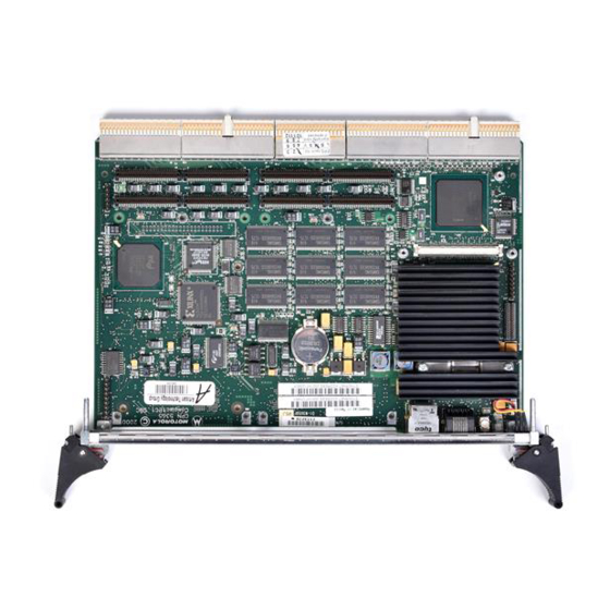
Hardware Preparation and Installation CPN5365 On-Board Components The CPN5365 carries components on both sides. Table 1-2 on page 1-9 lists the connectors available to support devices. There are no on-board jumpers. Slim Line Drive Dual Memory Mezzanine Modules 2928 0301 Figure 1-2. -
Page 30: Table 1-2. List Of Front Panel Connectors And On-Board Components
CompactPCI Bus Connector CompactPCI Bus Connector Rear I/O CompactPCI Connector Rear I/O CompactPCI Connector Rear I/O CompactPCI Connector (reserved for Motorola use only) Video connector COM1 (serial port - RJ45 connector) Ethernet connector (RJ45) Debug port PMC1 bus signal connector... -
Page 31: Installing Memory Modules, Pmcs, And Drives
Hardware Preparation and Installation Installing Memory Modules, PMCs, and Drives Refer to Antistatic Precautions on page 1-2 before beginning installation. Dangerous voltages, capable of causing death, are present in this equipment. Use extreme caution when handling, testing, and adjusting. Warning Avoid touching areas of integrated circuitry. -
Page 32: Mounting Pci Mezzanine Cards
7. Slide the edge connector of the PMC module into the front panel Caution opening from behind and place the PMC module on top of the base board. Align the four connectors on the underside of the PMC module with the corresponding connectors on the CPN5365: http://www.motorola.com/computer/literature 1-11... -
Page 33: Mounting The Slim Line Eide Hard Drive
Hardware Preparation and Installation – J11, J12, J13, J14 for PMC1 – J21, J22, J23, J24 for PMC2 Press all connectors until they are firmly seated. 8. Insert the four screws through the holes on the bottom side of the CPN5365 and tighten the screws. -
Page 34: Connecting Devices To Board Connectors
CPN5365 operates properly, you may need to make certain modifications by settings bits in control registers after installing the module in a system. Configuration options for the CPN5365 are: There are no on-card jumpers or switches You cannot configure the CPU speed settings http://www.motorola.com/computer/literature 1-13... -
Page 35: Before You Install Or Remove A Board
Boards may be damaged if improperly installed or handled. Please read and follow the guidelines in this section to protect your equipment. Observe ESD Precautions Motorola strongly recommends that you use an antistatic wrist strap and a Use ESD conductive foam pad when installing or upgrading a system. Electronic components, such as disk drives, computer boards, and memory modules, can be extremely sensitive to electrostatic discharge (ESD). -
Page 36: Use Caution When Installing Or Removing Boards
This LED is under software control. If your system is using software that provides full hot swap capabilities, the software will illuminate the blue hot swap LED on the faceplate when software has stopped and it is safe to remove the board. http://www.motorola.com/computer/literature 1-15... -
Page 37: Recognize Different Injector/Ejector Lever Types
Hardware Preparation and Installation If your system does not have hot swap-aware software running, behavior of the blue LED may be indeterminate. In this case, you may need to manually shut down applications or operating systems running on the board prior to board removal, even if the blue LED is lit. Powering down or removing a board before the operating system or other software running on the board has been properly shut down may cause corruption of data or file systems. -
Page 38: Verify Slot Usage
Card Rail Glyph Usage Color None MXP: Alarm Management Controller slot CPX: Hot Swap Controller or Bridge slot MXP: Fabric Switch Card slot CPX: System Controller slot Black MXP: Payload Card slot CPX: Non-system Controller or I/O Card slot http://www.motorola.com/computer/literature 1-17... -
Page 39: Installing A Module
Hardware Preparation and Installation Installing a Module This section describes a recommended procedure for installing a board module in a chassis. Before you install your module, please read all cautions, warnings, and instructions presented in this section and the guidelines explained in Before You Install or Remove a Board on page 1-14. - Page 40 5. When the module you are installing is completely latched, secure it by tightening the captive screws at both ends of the faceplate. http://www.motorola.com/computer/literature 1-19...
-
Page 41: Removing A Hot-Swap Module
Hardware Preparation and Installation Removing a Hot-Swap Module This section describes a recommended procedure for removing a board module from a chassis. Before you remove your module, please read all cautions, warnings, and instructions presented in this section and the guidelines explained in Before You Install or Remove a Board on page 1-14. - Page 42 Removing a Hot-Swap Module 4322 0804 4. Carefully pull the module from the chassis. http://www.motorola.com/computer/literature 1-21...
-
Page 43: Replacing Lithium Batteries
Hardware Preparation and Installation Replacing Lithium Batteries Follow these safety rules for proper battery operation and to reduce equipment and personal injury hazards when handling lithium batteries. Use the battery for its intended application only. Note Do not recharge, open, puncture or crush, incinerate, expose to high temperatures or dispose of in your general trash collection. - Page 44 3. Not the battery polarity and press the new battery into the socket. Note No soldering is required when the battery is in the socket. 4. Recycle or dispose of the old battery according to local regulations and manufacturer’s instructions. http://www.motorola.com/computer/literature 1-23...
-
Page 46: Transition Module On-Board Components And Rear Panel Connectors
2Installing the CPTM-01 The optional CPTM-01 TM gives you backplane I/O for PMC sites and on- board devices. Transition Module On-Board Components and Rear Panel Connectors The CPTM-01 rear transition module has connectors on the rear panel for: Keyboard/mouse (PS/2) Video (15 pin high density D-sub) COM2 (serial port) (9 pin D-sub) Ethernet 1 and Ethernet 2 (RJ45) -
Page 47: Figure 2-1. Cptm-01 Components And Rear Panel Connectors
Installing the CPTM-01 Table 2-1. Front Panel and On-Board Connectors and Components for the CPTM-01 (Continued) Connector Description Connector Description Floppy CompactFlash PIM connector (PMC I/O) IDE (secondary) Ethernet 1 Keyboard/Mouse (external) PIM connector (PMC I/O) COM2 (serial port 2) The following illustration shows the locations of on-board components and rear panel connectors on the CPTM-01. -
Page 48: Antistatic Precautions
Installing the CPTM-01 Transition Module Antistatic Precautions Use ESD Motorola strongly recommends that you use an antistatic wrist strap and a conductive foam pad when installing or upgrading a system. Electronic components, such as disk drives, computer boards, and memory modules, can be extremely sensitive to electrostatic discharge (ESD). - Page 49 CPN5365 is removed before the transition module is installed. Use ESD Motorola strongly recommends that you use an antistatic wrist strap and a conductive foam pad when installing or upgrading a system. Electronic components, such as disk drives, computer boards, and memory modules, can be extremely sensitive to ElectroStatic Discharge (ESD).
- Page 50 Transition Module Single Board Computer 2165 9803 5. Secure in place with the screws provided, making good contact with the transverse mounting rails to minimize RF emissions. 6. Replace the chassis or system cover(s), making sure no cables are pinched. http://www.motorola.com/computer/literature...
- Page 51 Installing the CPTM-01 7. Cable the peripherals to the panel connectors, reconnect the system to the AC or DC power source, and turn the equipment power on. Computer Group Literature Center Web Site...
-
Page 52: Cptm-01 Transition Module Connectors
PMC1IO40 PMC1IO41 PMC1IO42 PMC1IO43 PMC1IO44 PMC1IO45 PMC1IO46 PMC1IO47 PMC1IO48 PMC1IO49 PMC1IO50 PMC1IO51 PMC1IO52 PMC1IO53 PMC1IO54 PMC1IO55 PMC1IO56 PMC1IO57 PMC1IO58 PMC1IO59 PMC1IO60 PMC1IO61 PMC1IO62 PMC1IO63 PMC1IO64 VCC3 *Power to pins E18 and E19 are not supplied by the CPN5365 SBC. http://www.motorola.com/computer/literature... -
Page 53: Table 2-3. Signal Descriptions For Cptm-01 Rear I/O
Installing the CPTM-01 Table 2-3. Signal Descriptions for CPTM-01 Rear I/O Signal Signal Signal Description Mnemonic Universal Serial USDATAn+ (+) signal of differential data pair for USB channel Bus (Channel 0 and USDATAn- (-) signal of differential data pair for USB channel Channel 1) Serial COM Ports CTSn... - Page 54 CPTM-01 Transition Module Connectors Table 2-4. CPTM-01 Rear I/O Connector (J4) HSYNC DDCCLK VSYNC DDCDAT AFD- STB- ERR- INIT- SLCT SLIN- DRVDENS0 ACK- BUSY DSKCHG- HDSEL- RDATA- WPROT- TR0- WGATE- WDATA- STEP- DIR- MTR1- DS1- MTR0- INDEX- DRVDENS1 http://www.motorola.com/computer/literature...
-
Page 55: Table 2-5. Signal Descriptions For The Cptm-01 Backplane Connector (J4)
Installing the CPTM-01 Table 2-5. Signal Descriptions for the CPTM-01 Backplane Connector (J4) Signal Signal Signal Description Mnemonic Floppy Disk Drive DSKCHG- Indicates drive door is open DIR- Controls direction of the head during step operations DRVDENS[1:0] Disk density select communication DS[1:0]- Drive selects HDSEL-... -
Page 56: Table 2-6. Cptm-01 Rear I/O Connector (J5)
SCS1- SDMACK- KBDCLK RD1- TD1- SCS3- SIORDY RESET_IN AUXVCC2 SDMARQ SDIOW- MDAT RD2+ TD2+ SDA2 SDIOR- MCLK RD2- TD2- SDA1 SDA0 SDD15 AUXVCC1 SDD14 SDD13 SDD12 SDD11 SDD10 SDD9 SDD8 SDD7 SDD6 SDD5 SDD4 SDD3 SDD2 SDD1 SDD0 http://www.motorola.com/computer/literature 2-11... - Page 57 Installing the CPTM-01 Table 2-6. CPTM-01 Rear I/O Connector (J5) Table 2-7. Signal Descriptions for the CPTM-01 Backplane Connector (J5 Signal Signal Signal Description Mnemonic Miscellaneous AUXVCCn Auxiliary VCC power, fused at 0.75A maximum Digital signal ground plane EIDE (ATA-2), SDMARQ Drive DMA request Secondary...
-
Page 58: Pmc I/O Connectors
PMCxIO15 PMCxIO16 PMCxIO17 PMCxIO18 PMCxIO19 PMCxIO20 PMCxIO21 PMCxIO22 PMCxIO23 PMCxIO24 PMCxIO25 PMCxIO26 PMCxIO27 PMCxIO28 PMCxIO29 PMCxIO30 PMCxIO31 PMCxIO32 PMCxIO33 PMCxIO34 PMCxIO35 PMCxIO36 PMCxIO37 PMCxIO38 PMCxIO39 PMCxIO40 PMCxIO PMCxIO PMCxIO PMCxIO PMCxIO PMCxIO PMCxIO PMCxIO PMCxIO PMCxIO PMCxIO PMCxIO http://www.motorola.com/computer/literature 2-13... -
Page 59: Ethernet Connectors
Installing the CPTM-01 Table 2-8. PMC 1 and 2 I/O Connectors (J14, J10) (Continued) J14 and J10 Pin Number Signal Signal Pin Number PMCxIO PMCxIO PMCxIO PMCxIO PMCxIO PMCxIO PMCxIO PMCxIO PMCxIO PMCxIO PMCxIO PMCxIO Ethernet Connectors Table 2-9. CPTM-01 Ethernet Connectors (J18) and (J13) Signal Mnemonic Signal Description Differential transmit lines... -
Page 60: Serial Port Connectors
UART is ready to exchange data Sends serial data to communication link CTS- Data set is ready to exchange data DTR- Data set is ready to establish a communication link Modem has received a telephone ringing signal Ground CGND Chassis ground http://www.motorola.com/computer/literature 2-15... -
Page 61: Video Connector
Installing the CPTM-01 Video Connector Table 2-12. CPTM-01 Video Connector (J16) Signal Mnemonic Signal Description Red signal GREEN Green signal BLUE Blue signal no connection DACVSS Video return DACVSS Video return DACVSS Video return DACVSS Video return no connection DACVSS Video return no connection DDCDAT... -
Page 62: Universal Serial Bus Connectors
Causes printer to add a line feed Parallel data lines ERR- Set low when an error is detected Parallel data lines INIT- Initializes the printer Parallel data lines SLIN- Selects the printer Parallel data lines Ground Parallel data lines Ground Parallel data lines Ground http://www.motorola.com/computer/literature 2-17... - Page 63 Installing the CPTM-01 Table 2-15. CPTM-01 Parallel Connector (J20) Signal Mnemonic Signal Description Parallel data lines Ground Parallel data lines Ground ACK- Input is pulsed by the peripheral to acknowledge data retrieval BUSY Printer cannot accept any more data Printer is out of paper SELECT Set high when selected 2-18...
-
Page 64: Eide Connector
Drive register and data Drive register and data port address line port address line CS1- Chip select drive 0, also CS3- Chip select drive 1, also command register block command register block select select DASP- Drive active/slave present Ground http://www.motorola.com/computer/literature 2-19... -
Page 65: Compactflash Connector
Installing the CPTM-01 CompactFlash Connector Table 2-17. CPTM-01 CompactFlash Connector (J25) Signal Signal Description Signal Signal Description Mnemonic Mnemonic Ground Drive data line DD11 Drive data line Drive data line DD12 Drive data line Drive data line DD13 Drive data line Drive data line DD14 Drive data line... - Page 66 CPTM-01 Transition Module Connectors Table 2-17. CPTM-01 CompactFlash Connector (J25) (Continued) Signal Signal Description Signal Signal Description Mnemonic Mnemonic Drive data line Drive data line Drive data line Drive data line DD10 Drive data line Ground http://www.motorola.com/computer/literature 2-21...
-
Page 67: Floppy Connector
Installing the CPTM-01 Floppy Connector Table 2-18. CPTM-01 Floppy Connector (J9) Signal Mnemonic Signal Description Drive Common DRVDENS0 Disk density select communication Drive Common DRVDENS1 Disk density select communication Drive Common INDEX- Indicates the beginning of a track Drive Common MTR0- Motor enable outputs Drive Common... -
Page 68: Indicator Led/Miscellaneous Connector
+5 Volt power +5 Volt power EIDE_LEDa Secondary channel EIDE activity LED +5 Volt power EIDE_LEDb Primary channel EIDE activity LED +5 Volt power Ground PBRESET Pushbutton reset Ground CSEL- Tie this pin to ground to make the CompactFlash master http://www.motorola.com/computer/literature 2-23... -
Page 70: Applying Power To The System
3Starting Up the CPN5365 This chapter gives you information about the power-up procedure and the CPN5365 switches and indicators. Applying Power to the System After you verify that all necessary hardware preparation is complete and all connections are made correctly, you can apply power to the system. When you are ready to apply power to the CPN5365: Verify that the chassis power supply voltage setting matches the voltage present in the country of use (if the power supply in your... -
Page 71: Figure 3-1. Location Of The Debug Leds, Cpn5365 Secondary Side
Starting Up the CPN5365 Each Ethernet controller has two sets of indicator LEDs mounted on the back side of the board used to debug connection problems (DS3, DS4, DS5, and DS6). A green LED indicates a linked connection and an amber LED indicates packet transmit. -
Page 72: Figure 4-1. Block Diagram Of Cpn5365
4Functional Description This chapter provides a functional description of all major components and devices on the CPN5365. The following block diagram illustrates the major components and their circuitry on the CPN5365 Single Board Computer. Soldered-on memory: to 512MB PCI Bridge Memory mezzaine: to 512MB Memory Controller... -
Page 73: Chapter 4 Functional Description
Functional Description Pentium III Processor The CPN5365 supports a low power Intel Mobile Pentium III processor that is based on 0.18 micron process. The processor executes Intel MMX technology instruction for enhanced media and communication performance. It includes an integrated on-die L1 4-way associative L1 cache with 16KB instruction and 16KB write-back data cache, and an on- die 256KB, ECC protected cache data array, 8-way set associative L2 cache that operates at full core speed. -
Page 74: Intel 21555 Non Transparent Pci-To-Pci Bridge
CPCI lines.You can read these lines through the FPGA. Refer to the FPGA register description in the CPN5365 Single Board Computer Programmer’s Reference Guide for information about reading these bits. http://www.motorola.com/computer/literature... -
Page 75: Peripheral Reset Function
Functional Description Peripheral Reset Function In peripheral mode the PCI reset signal comes from the CompactPCI bus through the bridge to reset all on-card functions. You can reset the card independently without affecting other cards in the system. Reset Control Cpu Reset Chipset Intel 21555... -
Page 76: Peripheral Pci Clock Function
Clock Driver On-Card Intel 21555 Devices Bridge 2670 9911 Peripheral Hot Swap Function The CPN5365 complies with the CompactPCI Hot Swap Specification in peripheral mode. You must, however, use a compliant backplane with proper pin staging. http://www.motorola.com/computer/literature... -
Page 77: Field Programmable Gate Array Registers
Functional Description Field Programmable Gate Array Registers Use the system’s Field Programmable Gate Array (FPGA) for add-on features and control, and to connect to the internal ISA bus. The FPGA consists of a group of I/O registers for control of features such as a Watchdog Timer, I/O switching control, NVRAM control and decoding, and system management functions. -
Page 78: Jump To User Code In Alternate Flash Bank
The CPN5365 BIOS is compatible with the System Management BIOS Reference Specification, Version 2.3.1. You can get this specification on the Distributed Management Task Force, Inc. (DTMF) website. Refer to Appendix C, Related Documentation for information about how to access http://www.motorola.com/computer/literature... -
Page 79: Phoenixbios Description
Functional Description this document. The BIOS specification defines a way of reading this information through the BIOS using Plug and Play BIOS functions 50h - 5fh. The specification defines various structures used to store system information as data bytes and/or as ASCII strings. For example, the Type 0 structure stores BIOS information and the Type 1 structure stores system information. -
Page 80: Headless Operation
BIOS Setup-Advanced-PCI Configuration Menu. The CPN5365 BIOS stores specific information about the individual board in the Type 11 structure, in this null-terminated ASCII string format: [VPD] PRODUCT=CPN5365 BOARD_ASSEMBLY=01-W3658f01B BOARD_SN=1234567 BOARD_BUILD_DATE=01/15/2001 BIOS_VERSION=1.0RM01 BIOS_ASSEMBLY=98-W4079D06A [FAT] ENET1_MAC=0001 AF00 5F41 ENET2_MAC=0001 AF00 5F42 http://www.motorola.com/computer/literature... - Page 81 MAC addresses, different BIOS versions and different build dates. Other strings used in the Motorola manufacturing process. You can also use other tools that make it easier to develop applications that can access DMI data.
-
Page 82: Temperature And Voltage Monitoring On The Board And Processor
For programming information about the MAX1617 temperature sensor and LM81 system monitor, refer to Field Programmable Gate Array Registers on page 4-6, and Appendix C, Related Documentation. http://www.motorola.com/computer/literature 4-11... -
Page 84: Cpn5365 Single Board Computer Connectors
5Connector Pin Assignments This chapter gives you connector pin assignments for CPN5365 Single Board Computer. Pin assignments for the CPTM-01 are located in Chapter 2, Installing the CPTM-01. CPN5365 Single Board Computer Connectors CompactPCI Bus Connectors (J1 and J2) The CPN5365 Single Board Computer provides a 64-bit CompactPCI interface on connectors J1 and J2. - Page 85 Connector Pin Assignments Table 5-1. CPN5365 Backplane Connector (J1) AD[19] AD[20] VCC3 AD[21] AD[22] AD[23] IDSEL C/BE[3]# AD[24] AD[25] AD[26] AD[27] AD[28] AD[29] AD[30] AD[31] VCC3 REQ# GNT# RST# BRSVP1B5 BRSVP1A5 INTS INTP HLTY BRSVP1A4 INTD# INTC# INTB# INTA# +12V TRST# -12V Table 5-2.
- Page 86 Table 5-2. CPN5365 Backplane Connector (J2) GND AD[57] AD[58] AD[59] GND AD[60] AD[61] AD[62] AD[63] GND PAR64 C/BE[4]# C/BE[5]# GND C/BE[6]# C/BE[7]# BRSVP2B4 GND GNT4# REQ4# GNT3# CLK4 GND REQ3# GNT2# SYSEN# CLK3 CLK2 GND REQ2# GNT1# REQ1# CLK1 http://www.motorola.com/computer/literature...
-
Page 87: Compactpci Rear I/O Connectors (J3, J4, And J5)
Connector Pin Assignments CompactPCI Rear I/O Connectors (J3, J4, and J5) Table 5-3. CPN5365 Rear I/O Connector (J3) No connect USB0- USB0+ USB1- USB1+ No connect COM2_RI COM2_DTR COM1_RI COM1_DTR No connect COM2_DCD COM2_DSR COM1_DCD COM1_DSR No connect COM2_TxD COM2_CTS COM1_TxD COM1_CTS No connect... - Page 88 Request to send COMx_RXD Serial receive data COMx_TXD Serial transmit data COMx_RI Ring Indicator General Ground plane +/-3.3V, +/-5V Power PMC2 I/O PMC2IO [1 to 64] PMC channel 2 I/O signals 1 through 64 PMC VIO PMC VIO power (+3.3V) http://www.motorola.com/computer/literature...
-
Page 89: Table 5-5. Cpn5365 Rear I/O Connector (J4)
Connector Pin Assignments Connector J4 contains floppy, printer port and miscellaneous functions. J4 is an optional connector. Refer to the next two tables. Table 5-5. CPN5365 Rear I/O Connector (J4) PRSTDRV- PINTRQ PCS1- PDACK- PCS3- PIORDY PDREQ PIOW- PIOR- PD15 PD14 PD13 PD12... -
Page 90: Table 5-6. Signal Descriptions For The Backplane Connector (J4)
Paper end, indicates the printer is out of paper AFD- Auto feed, causes printer to line feed INIT- Initializes the printer SLIN- Select in, selects the printer STB- Data strobe, indicates data is valid SLCT Select, peripheral indicates it is selected http://www.motorola.com/computer/literature... -
Page 91: Table 5-7. Cpn5365 Rear I/O Connector (J5)
Connector Pin Assignments Table 5-6. Signal Descriptions for the Backplane Connector (J4) Signal Signal Signal Description Mnemonic EIDE (ATA-2), PDREQ- Drive DMA request Primary Channel PDACK- Drive DMA acknowledge PIOR- Drive I/O read PIOW- Drive I/O write PIORDY- Indicates drive is ready for I/O cycle(s) PD[15:0] Drive data lines, bits 15 -- 0 DRSTDRV... - Page 92 Table 5-8. Signal Descriptions for the Backplane Connector (J5) Signal Signal Signal Description Mnemonic Ethernet ERX1+, ERX1- Differential receive lines, Ethernet 1 ETX1+, ETX1- Differential transmit lines, Ethernet 1 ERX2+, ERX2- Differential receive lines, Ethernet 2 ERX2+, ETX2- Differential transmit lines, Ethernet 2 http://www.motorola.com/computer/literature...
- Page 93 Connector Pin Assignments Table 5-8. Signal Descriptions for the Backplane Connector (J5) Signal Signal Signal Description Mnemonic Keyboard/Mouse MCLK Clock for PS/2 mouse Device, TTL MDAT Serial data line for PS/2 mouse Levels KBDCLK Clock for PC/AT or PS/2 keyboard KBDDAT Serial data line for PC/AT or PS/2 keyboard Miscellaneous...
-
Page 94: Pci Mezzanine Card Connectors
INTD- PCI-RSVD Ground PCI_RSVD Ground Ground GNT- REQ- V (I/O) AD{31} AD[28} AD[27] AD[25] Ground Ground C/BE[3] AD[22] AD[21] AD[19] V (I/O) AD[17] FRAME- Ground Ground IRDY- DEVSEL- Ground Lock- SDONE- SBO- Ground V (I/O) AD[15] AD[12] AD[11] http://www.motorola.com/computer/literature 5-11... - Page 95 Connector Pin Assignments Table 5-9. PMC 1 and 2 Connectors (J11, J21) (Continued) J11 and J21 Pin Number Signal Signal Pin Number AD[09] Ground C/BE[0} AD[06] AD[05] AD[04] Ground V (I/O) AD[03] AD[02] AD[01] AD[00] Ground REQ64- Table 5-10. PMC 1 and 2 Connectors (J12, J22) J12 and J22 Pin Number Signal...
- Page 96 Signal Signal Pin Number AD[16] C/BE[2] Ground PMC-RSVD TRDY- +3.3V Ground STOP- PERR- Ground +3.3V SERR- C/BE[1] Ground AD[14] AD[13] Ground AD[10] AD[08] +3.3V AD[07] PMC-RSVD +3.3V PMC-RSVD PMC-RSVD Ground PMC-RSVD PMC-RSVD Ground PMC-RSVD ACK-64 +3.3V Ground PMC-RSVD http://www.motorola.com/computer/literature 5-13...
-
Page 97: 64 Bit Extension On The Pmc Connectors
Connector Pin Assignments 64 Bit Extension on the PMC Connectors Table 5-11. PMC 1 and 2 Connectors (J13, J23) J13 and J23 Pin Number Signal Signal Pin Number C/BE7# C/BE6# C/BE5# C/BE4# V(I/O) PAR64 AD63 AD62 AD61 AD60 AD59 AD58 AD57 V(I/O) AD56... -
Page 98: Pci Mezzanine Card 1 And 2 I/O
Pin Number Signal Signal Pin Number PMCxIO1 PMCxIO2 PMCxIO3 PMCxIO4 PMCxIO5 PMCxIO6 PMCxIO7 PMCxIO8 PMCxIO9 PMCxIO10 PMCxIO11 PMCxIO12 PMCxIO13 PMCxIO14 PMCxIO15 PMCxIO16 PMCxIO17 PMCxIO18 PMCxIO19 PMCxIO20 PMCxIO21 PMCxIO22 PMCxIO23 PMCxIO24 PMCxIO25 PMCxIO26 PMCxIO27 PMCxIO28 PMCxIO29 PMCxIO30 PMCxIO31 PMCxIO32 http://www.motorola.com/computer/literature 5-15... - Page 99 Connector Pin Assignments Table 5-12. PMC 1 and 2 I/O Connectors (J14, J24) (Continued) J14 and J24 Pin Number Signal Signal Pin Number PMCxIO33 PMCxIO34 PMCxIO35 PMCxIO36 PMCxIO37 PMCxIO38 PMCxIO39 PMCxIO40 PMCxIO PMCxIO PMCxIO PMCxIO PMCxIO PMCxIO PMCxIO PMCxIO PMCxIO PMCxIO PMCxIO PMCxIO...
-
Page 100: Memory Mezzanine Connector (J16)
+3.3V +3.3V DQ08 DQ09 DQ10 DQ11 DQ12 DQ13 DQ14 DQ15 DQ16 DQ17 DQ18 DQ19 DQ20 DQ21 DQ22 DQ23 +3.3V +3.3V DQ24 DQ25 DQ26 DQ27 DQ28 DQ29 DQ30 DQ31 DQ32 DQ33 DQ34 DQ35 DQ36 DQ37 DQ38 DQ39 +3.3V +3.3V http://www.motorola.com/computer/literature 5-17... - Page 101 Connector Pin Assignments Table 5-13. Memory Mezzanine Connector (J16) (Continued) Pin Number Signal Signal Pin Number DQ40 DQ41 DQ42 DQ43 DQ44 DQ45 DQ46 DQ47 DQ48 DQ49 DQ50 DQ51 DQ52 DQ53 +3.3V +3.3V DQ54 DQ55 DQ56 DQ57 DQ58 DQ59 DQ60 DQ61 DQ62 DQ63 CKD00...
- Page 102 CompactPCI Bus Connectors (J1 and J2) Table 5-13. Memory Mezzanine Connector (J16) (Continued) Pin Number Signal Signal Pin Number +3.3V +3.3V CS_C0_L CS_E0_L CS_C1_L CS_E1_L WE_L RAS_L CAS_L +3.3V/DQMA2 +3.3V/DQMA3 DQMB0 DQMB1 A1_SPD/DQMA4 A0_SPD/DQMB5 ME1_L/DQMA6 ME2_L/DQMA7 SDCLK1 SDCLK3 +3.3V SDCLK4 SDCLK2 http://www.motorola.com/computer/literature 5-19...
-
Page 103: Ethernet Connectors
Connector Pin Assignments Ethernet Connectors Refer to the following table for Ethernet connector pin assignments for the CPN5365 baseboard Ethernet (J9) connector.) Table 5-14. Ethernet Connector Pin Assignments for CPN5365 (J9) Pin Number Signal Mnemonic Signal Description Differential transmit lines Differential transmit lines Differential receive lines Differential receive lines... -
Page 104: On-Board Video Connector (J7)
Display Data Channel data signal for DDC2 support DDCCLK Display Data Channel clock signal for DDC2 support Debug Connector (J10) Table 5-17. Debug Connector (J10) Pin Number Signal Signal Pin Number RESET- PB_RESET- TCLK TRST- CPU_IOV PREQ- PRDY- http://www.motorola.com/computer/literature 5-21... - Page 105 Connector Pin Assignments Table 5-17. Debug Connector (J10) (Continued) Pin Number Signal Signal Pin Number HOST CLK 5-22 Computer Group Literature Center Web Site...
-
Page 106: Appendix A Specifications
Conforms to PICMG 2.0, CompactPCI (rev. 2.1) and PCI SIG 2.1 specifications Dimensions 4 HP (.8 inches) wide Refer to the next table for environmental specifications for the CPN5365 Single Board Computer in a Motorola supplied enclosure. Table A-2. Environmental Specifications Parameter Condition Specification... -
Page 107: Table A-3. Power Input Requirements For The Cpn5365 And Cptm-01
Specifications Table A-3. Power Input Requirements for the CPN5365 and CPTM-01 Input power Clock speed +5V @ 3.0A (15W) 500 MHz with 512 or 1024MB SDRAM +3.3V @ 2.5A (8.25W) +12V @ 100mA (1.2W) -12V @ 0A (0W) Total power = 24.5W +5V @ 3.0A (17.5W) 700 MHz with 512 or 1024MB SDRAM +3.3V @ 2.5A (8.25W) -
Page 108: Thermally Significant Components
These operating conditions vary depending on system design. Motorola Computer Group performs thermal analysis in a representative system to verify operation within specified ranges. Refer to Specifications, Table A-2. -
Page 109: Table B-1. Thermally Significant Components
Thermal Analysis The preferred temperature measurement location for a component may be: Junction - refers to the temperature measured by an on-chip thermal device Case - refers to the temperature at the top, center surface of the component Air - refers to the ambient temperature near the component Table B-1. - Page 110 Thermally Significant Components RESET 2897 0201 Figure B-1. Location of Thermally Significant Components on the Primary Side http://www.motorola.com/computer/literature...
- Page 111 Thermal Analysis 2898 0201 Figure B-2. Location of Thermally Significant Components on the Secondary Side Computer Group Literature Center Web Site...
-
Page 112: Component Temperature Measurement
Measuring Junction Temperature Some components have an on-chip thermal measuring device such as a thermal diode. For instructions on measuring temperatures using the on- board device, refer to the CompactPCI CPN5365 component manufacturer’s documentation listed in Appendix C, Related Documentation. - Page 113 Thermal Analysis Note Machining a heatsink base reduces the contact area between the heatsink and the electrical component. You can partially compensate for this effect by filling the machined areas with thermal grease. The grease should not contact the thermocouple junction.
-
Page 114: Figure B-3. Mounting A Thermocouple Under A Heatsink
Machined groove for Through hole for thermocouple thermocouple wire junction clearance (may require routing removal of fin material) Also use for alignment guidance during heatsink installation Thermal pad Heatsink base HEATSINK BOTTOM VIEW Figure B-3. Mounting a Thermocouple Under a Heatsink http://www.motorola.com/computer/literature... -
Page 115: Measuring Local Air Temperature
Thermal Analysis Measuring Local Air Temperature Measure local component ambient temperature by placing the thermocouple downstream of the component. This method is conservative since it includes heating of the air by the component. Figure B-4 shows one method of mounting the thermocouple. Tape thermocouple wire to top of component Thermocouple... -
Page 116: Motorola Computer Group Documents
CRelated Documentation Motorola Computer Group Documents The Motorola publications listed below are referenced in this manual, or apply to systems that use this product. You can obtain electronic copies of Embedded Communications Computing Group publications by: Contacting your local Motorola sales office, or Visiting the Embedded Communications Computing Groups’s... -
Page 117: Table C-2. Manufacturers' Documents
Related Documentation Manufacturers’ Documents For additional information, refer to the following table for manufacturers’ data sheets and user’s manuals. For your convenience, a source for the listed document is also provided. It is important to note that in many cases, the information shown is preliminary and the revision levels of the documents are subject to change without notice. - Page 118 Motorola Computer Group Documents Table C-2. Manufacturers’ Documents (Continued) Publication Document Title and Source Number MAX1617 Remote/Local Temperature Sensor with SMBus Serial 1855.pdf Interface; Maxim Corporation; http://pdfserv.maxim-ic.com/arpdf/1855.pdf National Semiconductor LM81 Microprocessor System Hardware Monitor LM81.html National Semiconductor Corporation; http://www.national.com/ PC97307VUL (Super I/OTM Enhanced Sidewinder Lite) Floppy Disk PC97307.html...
-
Page 119: Related Specifications
Related Specifications For additional information, refer to the following table for related specifications. For your convenience, a source for the listed document is also provided. It is important to note that in many cases, the information is preliminary and the revision levels of the documents are subject to change without notice Table C-3. - Page 120 Open HCI Release 1.0 Compaq Corporation, Microsoft Corporation, National Semiconductor 12/15/95 http://www3.compaq.com/support http://www.national.com/ http://www.microsoft.com/ IrDA SIR Data Specification IrDA SIR data Speci- Infrared Data Association fication http:/www.irda.org/standards/specifications.asp “El Torito” Bootable CD-ROM Specification, Version 1.0 specs-cdrom.pdf Phoenix Technologies, Inc. http://www.phoenix.com/ http://www.motorola.com/computer/literature...
- Page 122 Index Numerics on-board components CPTM01 21555 components and connectors advantages description xvii installation About This Manual xvii interfaces airflow alternate flash bank debug LEDs antistatic wrist strap 1-2, documentation applying power related battery 1-22 environmental specifications board equipment required installation 1-18 ESD 1-2, boards...
- Page 123 1-22 serial port 2-15, 5-20 lithium battery 2-17 local air temperature power input requirements measuring product overview 1-1, publications Motorola memory mezzanine cards mounting 1-10 mezzanine cards 1-11 rear panel connectors mounting 1-10 related documentation model numbers xvii...
- Page 124 URLs user code user documents Motorola watchdog timer http://www.motorola.com/computer/literature IN-3...