
Related Manuals for Samsung MCU-Y6NEE


Summary of Contents for Samsung MCU-Y6NEE
- Page 1 MCU-Y6NEE MCU-Y4NEE MCU-Y4NEE1 installation manual imagine the possibilities Thank you for purchasing this Samsung product. To receive more complete service, please register your product at www.samsung.com/register DB98-33933A(2)
-
Page 2: Table Of Contents
Contents Safety precautions ..........................................3 Preparing the installation ........................................5 Space requirements ..........................................7 Installing the unit ........................................... 8 Refrigerant piping works ......................................... 11 Wiring works ............................................17 Commisioning ............................................23... -
Page 3: Safety Precautions
Safety precautions The safety information and precautions below must be kept for the safety of users and installers. Before installing an air conditioner, please read this manual thoroughly to ensure that you know how to safely and efficiently install a new appliance. ... - Page 4 Safety precautions FOR INSTALLATION WARNING Make sure to connect wires thoroughly and fix them firmly so that no outer pressure of the wires would put on the terminal block. If the terminal is loose, it may generate heat and cause a fire. ...
-
Page 5: Preparing The Installation
Preparing the installation Accessories Please check if items below are included in installation accessories. Name Y-connector(Φ9.52,Φ15.88) Pipe socket Drain socket Shape Insulation (for base) Name Insulation (for pipe) Installation manual Pattern sheet Cable tie Shape Selecting the refrigerant pipe for installation The design pressure of MCU for R410a is about 4.1 MPa. - Page 6 Preparing the installation MCU indoor/outdoor unit compatible table Before installing MCU, refer to the compatible table below and find the model before installation. Outdoor Unit Indoor Unit AVXC✴✴✴✴✴✴✴ MCU-Y6NEE AVXW✴✴✴✴✴✴✴ MCU-Y4NEE AVXT✴✴✴✴✴✴✴ AVXD✴✴✴✴✴✴✴ RD✴✴✴HRXGA✴ MCU-Y4NEE1 ND200/220/280 ✴✴✴✴✴✴✴ Model Description MCU-Y6NEE Below 6 indoor units, below 46.4kW...
-
Page 7: Space Requirements
Space requirements 1. Since refrigerant noise can be generated during the MCU operation, do not install the unit on the ceiling of the places that requires silence such as bedrooms, libraries, hospitals and offices etc. 2. Do not install the MCU in the ceiling of the living area. Otherwise, noise generated from the MCU may disturb people in that area and cause inconvenience. -
Page 8: Installing The Unit
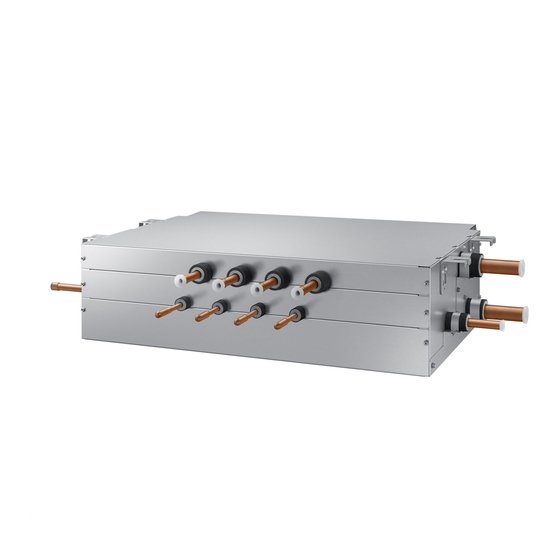
400mm or 500mm or more more 700mm or more Installing the unit 1. MCU specification Model MCU-Y6NEE MCU-Y4NEE MCU-Y4NEE1 The exterior of MCU Up to 2 units Number of connectable indoor Up to 6 units Up to 4 units Only for large capacity duct units (20.0kW) - Page 9 2. Installing the indoor unis Model MCU-Y6NEE MCU-Y4NEE MCU-Y4NEE1 Example installing Large capacity duct unit : Use Under 10.0kW indoor unit : Don't use Y-connector Installing Y-connector at the Gas & Liquid Line indoor 11.2kW ~ 14.0kW indoor unit : Use Y-connector at the Gas & Liquid Line Only for large capacity duct ❈ Can not connect to large capacity duct (20.0kW Over) units ❈ (20.0kW Over) 3. Preparation before installation. 1) P lace the pattern sheet on the ceiling at the spot where you want to install the indoor unit. • S ince the diagram is made of paper, it may shrink or stretch slightly due to temperature or humidity. For this reason, before drilling the holes maintain the correct dimensions between the markings.
- Page 10 Installing the unit 5. How to connect the pipe line. 70mm Protect with wet towel when 70mm brazing Pipe connection from outdoor unit Low pressure gas pipe connection (Brazing) High pressure gas pipe connection (Brazing) Liquid pipe connection (Flare) Pipe connection to indoor unit Liquid pipe(Flare) Gas pipe (Flare) When installing MCU, use the pattern sheet for installation that is provided with the product.
-
Page 11: Refrigerant Piping Works
Refrigerant piping works For installation of the refrigerant pipes, please refer to corresponding outdoor unit installation manual. Since R410a has a high working pressure, only use the regulated refrigerant pipe and follow proper installation method. Finish the gas pipe and the liquid pipe works with the insulation base. If the insulation work isn’t done properly, ... - Page 12 Refrigerant piping works Selecting the refrigerant pipe When selecting the refrigerant pipe, refer to the table below. (The amount of additional MCU refrigerant : 0.5 Kg) Outdoor unit connection pipe size : (A1), (A2), (A3) Branch joint : (D), (E), (F) A1 : S elect the pipes according to the outdoor unit ■ Branch joint of outdoor unit’s multi 12HP 14HP 16HP capacity with following table. connection (D) A2 : S elect the pipes according to sum of outdoor Capacity of Model unit capacities behind the outdoor joint with...
- Page 13 Simultaneous heating and cooling- Additional refrigerant Additional refrigerant charging ■ Additional refrigerant is charged according to the length and size of liquid pipe. • Example) Additional refrigerant charging Liquid pipe size (O.D. mm) Additional refrigerant charging (kg/m) Ø6.35 0.02 61.6kW Ø9.52 0.06 Ø12.70 0.125 Ø12.70(1m) Ø15.88 0.18...
- Page 14 Refrigerant piping works Method and cautions on brazing the pipe Keeping refrigerant pipe clean and dry To prevent foreign materials or water from entering the pipe, it is important to keep the refrigerant pipe clean, dry and sealed during installation. Exposure place Exposure time Sealing type...
- Page 15 5. Select the insulation of the refrigerant pipe. Insulate the gas side and liquid side pipe referring to the thickness according to the pipe size. Indoor temperature of 30°C and humidity of 85% is the standard condition. If install in a high humidity condition, use one grade thicker ...
- Page 16 Refrigerant piping works Draining form Without the drain pump 1. Install horizontal drainpipe with a slope of 1/100 or more and fix it by hanger space of 1.0~1.5m. 2. Install U-trap at the end of the drainpipe to prevent a nasty smell to reach the indoor unit. 3.
-
Page 17: Wiring Works
Wiring works Installing the circuit breaker and wires Power supply MCCB Power cable Earth cable Communication cable X A, 30mmA Max : 242V 2.5mm 2.5mm 0.75~1.5mm Min : 198V 0.1 sec Decide the capacity of ELB and MCCB by below formula. ... - Page 18 Wiring works Rated current Unit Model Rating current (A) 0.20 ✴✴022✴✴ AVXCS✴✴ 0.23 ✴✴028✴✴ 0.25 ✴✴036✴✴ 0.38 ✴✴052✴✴ 0.38 ✴✴056✴✴ AVXC2✴✴ 0.40 ✴✴060✴✴ 0.40 ✴✴071✴✴ 0.40 ✴✴072✴✴ 0.15 ✴✴045✴✴ 0.15 ✴✴056✴✴ 0.21 ✴✴071✴✴ ND✴✴✴4✴✴✴ 0.30 ✴✴090✴✴ 0.36 ✴✴112✴✴ 0.36 ✴✴128✴✴ 0.45 ✴✴140✴✴...
- Page 19 Installing the wire Supply the 220-240V power to L, N of MCU separately with outdoor unit. Connect the communication cable from the outdoor unit to F1, F2 of MCU. Power Line and communication line must be connected as shown in drawing. ...
- Page 20 Wiring works Setting address and option PCB Layout Turn off the DIP switch on the MCU PCB when pipe is not connected. DIP switch for indoor unit setting (ON:Use, OFF:Not use) Rotary switch for indoor unit ADDRESS Rotary switch for MCU ADDRESS Setting MCU address Set the rotary switch of the indoor unit ADDRESS on the MCU PCB same as the ADDRESS of connected indoor unit.
- Page 21 Setting MCU option DIP switch for indoor unit setting (ON:Use, OFF:Not use) Rotary switch for Indoor unit ADDRESS Rotary switch for MCU ADDRESS How to set up Set the rotary switch located at outdoor unit PCB to match the number of connected indoor units (8). ...
- Page 22 Wiring works Key operation Display MCU Display indoor EEV valve status unit's address passive control Display segment Display Contents Remarks (Pushed time) Blank MCU address 0 Blank MCU address 1 MCU address Blank MCU address 2 Blank MCU address 11 Blank MCU address 15 Mode switching EEV1 step...
-
Page 23: Commisioning
K4 Switch (Electronic Valve Manual Control) According to the push time of K4 Switch, A_C, A_H, …, F_C, F_H, Liquid bypass solenoid valve opens in order. In Electronic Valve Manual Control mode, valve operates by K4 Push time irrespective of indoor operation mode. ...