Advertisement
Quick Links
Installationsanleitung
IQ8Wireless universelles Funkinterface
Installation Instruction
IQ8Wireless Interface
(Art.-Nr. / Part No. 805601 / 805602)
Technische Änderungen vorbehalten!
798944
Technical changes reserved!
D
GB
01.2009
© 2009 Honeywell International Inc.
Novar GmbH a Honeywell Company
Dieselstraße 2, D-41469 Neuss
Internet:
www.esser-systems.de
E-Mail:
info@esser-systems.de
D
In das IQ8Wireless universelles Funkinterface dürfen
ausschließlich die freigegebenen Batterien (Art.-Nr.
805597) eingesetzt werden. Die Betriebszeit der
Batterien
ist
abhängig
von
Meldertyp, der Anwendungstemperatur und weiteren
Umgebungsbedingungen. Batterien max. 3 Jahre
lagern, Produktionsdatum beachten!
Explosionsgefahr
bei
unsachgemäßen
wechsel! Entsorgung der Batterien gemäß Hersteller-
angabe!
Das IQ8Wireless Funkinterface (Art.-Nr. 805601/-02)
entspricht bei bestimmungsgemäßer Anwendung
den grundlegenden Anforderungen gemäß Artikel 3
der R&TTE-Richtlinie 1999/5/EG.
Weitere
Hinweise
in
der
Dokumentation
IQ8Wireless Teilnehmer beachten!
Ergänzende und aktuelle Informationen
Die Produktangaben entsprechen dem Stand der
Drucklegung und können durch Produktänderungen,
geänderte Normen / Richtlinien ggf. von den hier
genannten Informationen abweichen.
Aktualisierte
Informationen
erklärungen siehe www.esser-systems.de!
GB
The IQ8Wireless interface must be operated only with
the approved and recommended batteries (Part No.
805594). The battery lifetime depends on the
assigned
type
of
fire
detector,
temperature and other ambient conditions. Battery
storage up to max. 3 years, observe date of birth!
Danger
of
explosion
in
case
replacement of the battery! Battery waste disposal by
manufacturer instruction!
If used properly, the IQ8Wireless interface (Part No.
805601/-02) complies with the basic directives and
corresponding requirements in according to the
R&TTE Directive 1999/5/EC.
Observe additional information in the documentation
of the IQ8Wireless devices!
Additional and updated Informations
The product specification relate to the date of issue
and may differ due to modifications and/or amended
Standards
and
Regulations
informations.
For
updated
informations
conformity refer to www.esser-systems.de.
Achtung!
Diese Anleitung ist vor der Inbetriebnahme genau durchzulesen. Bei
Schäden die durch Nichtbeachtung dieser Anleitung verursacht
werden, erlischt der Garantieanspruch. Für Folgeschäden, die
daraus resultieren, wird keine Haftung übernommen.
Allgemein
Das
IQ8Wireless
Anschaltung von Komponenten der Serie IQ8 an einen
IQ8Wireless Funkkoppler oder ein IQ8Wireless Funkgateway.
Art.-Nr.
805601
805602
Systemanforderungen
•
Zur Anbindung an den esserbus
IQ8Control ab Systemsoftware V3.06 R0001 sowie der
IQ8Wireless Funkkoppler (Art.-Nr. 805595) und/oder das
IQ8Wireless Funkgateway (Art.-Nr. 805594) erforderlich (Abb. 5).
•
Für die Anbindung an eine Standard-Meldergruppe eines
Brand- oder Gefahrenmeldesystems ist der IQ8Wireless
Funkkoppler (Art.-Nr. 805595) erforderlich (Abb.6).
•
Programmiersoftware tools 8000 ab Version V1.09.
Projektierungshinweise
Der Montageort ist gemäß den nationalen bzw. lokalen Richtlinien
und Auflagen zu wählen. Zu beachten ist, dass die Reichweite
abhängig von den Umgebungsbedingungen (z.B. Betonwänden,
-decken und Umgebungstemperatur) erheblich eingeschränkt
werden kann. Die optimale Position bzw. max. Reichweite kann
mit der Feldstärkenanzeige in der Programmiersoftware tools
8000 bestimmt werden.
•
Max. 10 IQ8Handfeuermelder (mit rotem Meldergehäuse) über
ein IQ8Wireless Funkinterface pro IQ8Wireless Funkkoppler/
Funkgateway (gemäß VdS).
•
Die Verwendung der externen D-Linie und des Relaisausgangs
der IQ8Hand(feuer)melder ist nicht möglich.
Weitere Projektierungshinweise in der Dokumentation
der zugehörigen IQ8 Funkteilnehmer beachten!
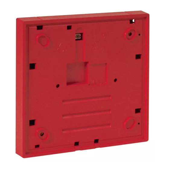
Montage / Installation
1. Rückwand auf einer glatten, geeigneten Wand z.B. mit den
beiliegenden vier Dübeln und vier Schrauben befestigen
(Abb.1).
2. IQ8Hand(feuer)melder mit dem beiliegenden Kabel (D) an die
Steckverbindung (E) anschließen.
Alternativ kann auch der Eingang "C IN"
Montage genutzt werden (Abb. 2).
3. IQ8Hand(feuer)melder aufsetzen und mit den entsprechenden
Gewindeschrauben - im Beipack enthalten - montieren (siehe
Abb. 1 / 3). Bei Hand(feuer)meldern "kleine Bauform" Option
704967 (mit weißer Blende gem. VdS) einsetzen (Abb. 4).
4. Vier Batterien (Art.-Nr. 805597) lagerichtig in das IQ8Wireless
Funkinterface einsetzen (Abb. 2).
5. Leuchtet nach dem Einsetzen der Batterien die LED B, kurz
den Reset-Taster drücken. Die LED A blinkt jetzt und das
IQ8Wireless Funkinterface ist betriebsbereit (Abb. 2).
6. Zum Schließen das Gehäuseoberteil inkl. IQ8Hand(feuer)-
melder leicht angekippt auf die Vertiefung (A) der Rückwand
aufsetzen und vorsichtig andrücken bis die Halterung (B)
einrastet. VdS-Hinweis (Abb. 1) beachten!
Demontage
Kunststoffniete (F) entfernen, Schlüssel (C) mit den beiden
dem
eingesetzten
Kunststoffzapfen
einstecken und die Verriegelung aufdrücken. Das IQ8Wireless
Funkinterface inkl. dem jeweiligen Aufsatz leicht nach oben
ankippen und von der Rückwand abnehmen (Abb. 1). Bei der
Batterie-
Entnahme des angeschlossenen Gerätes erfolgt im Normalbetrieb
eine Störungsmeldung.
Inbetriebnahme
Die
Zuordnung
IQ8Wireless Funkkoppler oder IQ8Wireless Funkgateway erfolgt
über die Programmiersoftware tools 8000. Der Ladezustand der
Batterien wird automatisch überprüft und der erforderliche Austausch
der
kann als Melderstörung an dem IQ8Wireless Funkkoppler und/oder
der Brandmelderzentrale angezeigt werden.
Die Batterien müssen kurzfristig, innerhalb von 14 Tagen
nach der Störungsmeldung, ausgetauscht werden.
Die Betriebszeit der Batterien kann durch erhöhten
Stromverbrauch der Funkteilnehmer im Alarmfall, bei
Funkstörungen oder schlechter Funkstrecke sowie durch
und
Konformitäts-
den
erheblich eingeschränkt werden.
LED Statusanzeige A/B
LED B blinkt
Reset-Taster drücken
LED A blinkt
LED A aus
Technische Daten
Betriebsspannung
Betriebszeit
the
ambient
Stromaufnahme
Frequenzband
of
inappropriate
Reichweite
Umgebungstemperatur
Lagertemperatur
- ohne Batterien
- mit Batterien
Luftfeuchte
Schutzart
Material
Farbe
Gewicht
from
the
given
Maße (B x H x T)
and
declaration
of
Spezifikation
VdS-Anerkennung
CE-Zertifikat
D
Funkinterface
ermöglicht
die
Bezeichnung
IQ8Wireless universelles Funkinterface, rot
IQ8Wireless universelles Funkinterface, weiß
®
ist die Brandmelderzentrale
für die abgesetzte
in
die
Öffnung
der
Gehäuseunterseite
des
IQ8Wireless
Funkinterface
Übergangswiderstand
an
den
Kontakten
IQ8Wireless Funkinterface nicht betriebsbereit
LED B aus
LED A blinkt
Normalbetrieb
IQ8Wireless Funkinterface ist zugeordnet
:
4 Batterien je 3,6V (AA)
:
3 bis max. 5 Jahre
:
ca. 30 µA
:
433 / 868 MHz
:
bis max. 300 m
:
-5 °C bis +55 °C
:
-20 °C bis +70 °C
+25 °C ± 10 °C
:
≤ 95 % rel. Feuchte
:
(ohne Betauung)
:
IP 42
:
PC/ASA-Kunststoff
rot, ähnlich RAL 3020
:
weiß, ähnlich RAL 9010
:
ca. 285 g inkl. Batterien
(ohne Aufsatz)
:
135 x 135 x 20 mm
(ohne Aufsatz)
:
EN 54-18
:
G 206092
:
0786-CPD-20623
Caution!
Read these instructions carefully before starting assembly. Claims
under warranty will be invalidated in the event of damage caused
by non-compliance with the installation instructions. No liability is
accepted for any resulting consequential loss or damage.
General
kabellose
The IQ8Wireless interface provides the wireless connection of
series IQ8 devices to an IQ8Wireless transponder or IQ8Wireless
gateway.
Part No.
Description
805601
IQ8Wireless universal interface , red
805602
IQ8Wireless universal interface , white
System requirements
•
®
For an esserbus
analog loop connection the Fire Alarm
Control Panel with system software from V3.06 R0001 and the
IQ8Wireless transponder (Part No. 805595) and/or the
IQ8Wireless gateway (Part No. 805594) ist required (Fig. 5).
•
Connection of this device to a conventional detector zone of a
Fire
alarm
system
transponder (Part No. 805595).
•
Programming software tools 8000 from Version V1.09.
Planning information
The mounting location must comply with national or local
guidelines and regulations. Observe that the range can be
considerably restricted depending on the ambient conditions (e.g.
concrete walls, ceilings and the ambient temperature). The
optimum position and max. range can be determined with the field
strength indicator in the programming software tools 8000.
•
Up to 10 IQ8Manual call points (with red housing) via
IQ8Wireless interface per IQ8Wireless transponder/ Wireless
gateway (according to VdS).
•
The external D line and the relay output of the IQ8Manual Call
Point cannot be used.
Observe additional planning information in the manuals
of the associated IQ8Wireless devices!
Mounting / Installation
1. Fix the back of the IQ8Wireless interface to a suitable, smooth
wall, e.g. with the enclosed four plugs and four screws (Fig.1).
2. Connect the IQ8Manual call point to the plug connection (E) of
the IQ8Wireless interface with the enclosed cable (D).
Alternatively it is possible to connect the input "C IN"
greater mounting space between the devices (Fig. 2).
3. Place the IQ8Manual call point on to the IQ8Wireless interface
and connect it with the supplied screws - enclosed package
(Fig. 1 / 3). For MCPs "small housing" use option 704967 (Fig.
4) with white cover (according to VdS).
4. Insert four batteries (Part No. 805597) in the correct position in
the IQ8Wireless interface (Fig. 2).
5. If LED B lights after you have inserted the batteries, briefly
press the reset button. LED A should now flash and the
IQ8Wireless interface is ready for operation (Fig. 2).
6. To close the top part of the housing including the IQ8Manual
call point, place it on the back groove (A) at a slight angle and
carefully apply pressure until the holder (B) clicks into place.
Refer to VdS information (Fig. 1)!
Dismantling
Remove plastic rivet (F), insert key (C) with the two plastic pins
into the opening on the bottom of the housing and press the catch
open. Tip the IQ8Wireless interface including the attachment
lightly upward and remove it from the back of the housing (Fig. 1).
Removing the connected device will cause a fault message during
normal operation.
Commissioning
The IQ8Wireless interface is assigned to an IQ8Wireless
zu
einem
transponder or an IQ8Wireless gateway via the programming
software
tools
8000.
automatically and if they need to be replaced, this can be
displayed as a fault message on the IQ8Wireless transponder
and/or the Fire Alarm Control Panel.
The batteries must be replaced within 14 days after the
fault message.
The battery lifetime may be reduced by an increased
current consumption during the alarm condition, due to
transmission faults or poor signal strength as well as by
the transition resistance of the battery contacts.
ggf.
LED status display A/B
LED B flashes
IQ8Wireless interface is not ready for operation
press reset button
LED B off
LED A flashes
Normal mode
LED A off
IQ8Wireless interface is assigned
Specifications
Operating voltage
Operating time
Current consumption
Frequency band
Range
Ambient temperature
Storage temperature
- without batteries
- with batteries
Humidity
IP rating:
Material
Colour
Weight
Dimensions (W x H x D)
Specification
VdS Approval
CE certificate
GB
(Fig.
6)
requires
the
IQ8Wireless
for a
The
battery
condition
is
checked
LED A flashes
:
4 x 3.6V (AA) batteries
:
3 to max. 5 years
:
approx. 30 µA
:
433 / 868 MHz
:
to max. 300 m
:
-5 °C to +55 °C
:
-20 °C to +70 °C
+25 °C ± 10 °C
:
≤ 95 % rel. Humidity
:
(non-condensing)
:
IP 42
:
PC/ASA plastic
red, similar to RAL 3020
:
white, similar to RAL 9010
:
approx. 285 g incl. Batteries
(without attachment)
:
135 x 135 x 20 mm
(without attachment)
:
EN 54-18
:
G 206092
: 0786-CPD-20623
Advertisement

Related Manuals for Honeywell ESSER IQ8Wireless


Summary of Contents for Honeywell ESSER IQ8Wireless
- Page 1 Technical changes reserved! Programmiersoftware tools 8000 ab Version V1.09. Programming software tools 8000 from Version V1.09. 01.2009 © 2009 Honeywell International Inc. Projektierungshinweise Planning information Der Montageort ist gemäß den nationalen bzw. lokalen Richtlinien The mounting location must comply with national or local und Auflagen zu wählen.
- Page 2 Montage / Mounting Rückseite / Rear side Reset Zugentlastung / Cord grip Batterien / Batteries max. 3 m IQ8Hand(feuer)melder IQ8Manual Call Point Bei Einsatz in VdS-gemäßen Brandmeldeanlagen, Schwimmhaut durchstoßen und schwarze Kunststoffniete (F) aus Beipack einsetzen! For installation in Fire alarm systems according to the VdS requirements, pierce gasket and insert the supplied black plastic rivet (F)! Abb.