Table of Contents
Advertisement
Quick Links
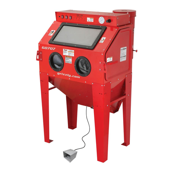
MODEL G0707
24" X 37" BLAST CABINET
OWNER'S MANUAL
(For models manufactured since 01/21)
COPYRIGHT © NOVEMBER, 2009 BY GRIZZLY INDUSTRIAL, INC. REVISED MARCH, 2021 (JL)
WARNING: NO PORTION OF THIS MANUAL MAY BE REPRODUCED IN ANY SHAPE
OR FORM WITHOUT THE WRITTEN APPROVAL OF GRIZZLY INDUSTRIAL, INC.
#CR12334 PRINTED IN CHINA.
V3.03.21
Advertisement
Table of Contents

Related Manuals for Grizzly G0707

Summary of Contents for Grizzly G0707
- Page 1 OWNER'S MANUAL (For models manufactured since 01/21) COPYRIGHT © NOVEMBER, 2009 BY GRIZZLY INDUSTRIAL, INC. REVISED MARCH, 2021 (JL) WARNING: NO PORTION OF THIS MANUAL MAY BE REPRODUCED IN ANY SHAPE OR FORM WITHOUT THE WRITTEN APPROVAL OF GRIZZLY INDUSTRIAL, INC.
- Page 2 This manual provides critical safety instructions on the proper setup, operation, maintenance, and service of this machine/tool. Save this document, refer to it often, and use it to instruct other operators. Failure to read, understand and follow the instructions in this manual may result in fire or serious personal injury—including amputation, electrocution, or death.
-
Page 3: Table Of Contents
Table of Contents INTRODUCTION ..........................2 Manual Accuracy ........................2 Contact Info ..........................2 Machine Description ........................2 Identification ..........................3 Data Sheet ..........................4 Machine Data Sheet ........................4 SECTION 1: SAFETY ........................6 Safety Instructions for Machinery ....................6 Additional Safety for Blast Cabinets ................... -
Page 4: Introduction
The cabinet is equipped with two side loading doors for ease of workpiece loading and unloading. Media is quickly unloaded through the hopper dump port door, and reloaded through a side door. Model G0707 (Mfd. Since 01/21) -
Page 5: Identification
H. Hopper Dump Chute B. Pressure Regulator w/Gauge Gloves C. Dust Collector Foot Pedal Blasting Switch D. Fluorescent Lamp Assembly K. Heavy Duty Leg Support System E. Canister Plunger for Filter Cleaning Viewing Window Side-Loading Door Model G0707 (Mfd. Since 01/21) -
Page 6: Data Sheet
Maximum Abrasive Capacity ............................400 lbs. Suggested Abrasive Capacity ............................55 lbs. Abrasive Type ................................Dry Only Load & Unload Access ..............................Sides Maximum Load Capacity ............................... 132 lbs. Design Type ................................Floor Model Model G0707 (Mfd. Since 01/21) Model G0707 Page 1 of 2... - Page 7 Included Dust Collector Filter Screened Work Table Foot Pedal Blasting Control Gun Blasting System Hands-Free Blasting System Hopper Dump Gate Easy-Clean Dust Collector Reusable Dust Collector Filter Element External Lighting System Model G0707 Page 2 of 2 Model G0707 (Mfd. Since 01/21)
-
Page 8: Section 1: Safety
Never operate under the influence of drugs or injury or blindness from flying particles. Everyday alcohol, when tired, or when distracted. eyeglasses are NOT approved safety glasses. Model G0707 (Mfd. Since 01/21) - Page 9 EXPERIENCING DIFFICULTIES. If at any time debris. Make sure they are properly installed, you experience difficulties performing the intend- undamaged, and working correctly BEFORE ed operation, stop using the machine! Contact our operating machine. Technical Support at (570) 546-9663. Model G0707 (Mfd. Since 01/21)
-
Page 10: Additional Safety For Blast Cabinets
If normal safety pre- Failure to do so could result in serious per- sonal injury, damage to equipment, or poor cautions are overlooked or ignored, serious personal injury may occur. work results. Model G0707 (Mfd. Since 01/21) -
Page 11: Section 2: Power Supply
Model G0707 (Mfd. Since 01/21) - Page 12 Two-prong outlets do not meet the grounding requirements for this machine. Do not modify or use an adapter on the plug provided—if it will not fit the outlet, have a qualified electrician install the proper outlet with a verified ground. -10- Model G0707 (Mfd. Since 01/21)
-
Page 13: Section 3: Setup
IMPORTANT: Save all packaging materials until you are completely satisfied with the machine and have resolved any issues between Grizzly or the shipping agent. You MUST have the original pack- aging to file a freight claim. It is also extremely helpful if you need to return your machine later. -
Page 14: Inventory
" x 10" .. 5 O. Lamp Window Dust Sheets 21 ⁄ " x 4" ..5 Bolt Bag ............1 —Cabinet Screws ⁄ -20 x ⁄ " ....26 — Flange Nuts ⁄ "-20 ........ 26 -12- Model G0707 (Mfd. Since 01/21) -
Page 15: Hardware Recognition Chart
Hardware Recognition Chart -13- Model G0707 (Mfd. Since 01/21) -
Page 16: Site Considerations
Only install in an Shadows, glare, or strobe effects that may distract access restricted location. or impede the operator must be eliminated. 81" 22" 22" 35" Figure 4. Space required for full range of movement. -14- Model G0707 (Mfd. Since 01/21) -
Page 17: Mounting To Shop Floor
Anchor studs are stronger and more per- manent alternatives to lag shield anchors; however, they will stick out of the floor, which may cause a tripping hazard if you decide to move your machine. -15- Model G0707 (Mfd. Since 01/21) -
Page 18: Air Supply Setup
If even small amounts of fine media dust enter the compressor through the intake or during general service, rings, pistons, valves, and bearings can be quickly destroyed. -16- Model G0707 (Mfd. Since 01/21) -
Page 19: Assembly
Attach the two side supports (Figure 7) to the left and right set of legs with four cabinet screws and flange nuts. Figure 9. Suction port baffle. With the help of an assistant, stand the blast cabinet upon the legs. -17- Model G0707 (Mfd. Since 01/21) - Page 20 10. Working from inside of the canister, insert the the inside of the cabinet viewing window and canister plunger through the canister wall so the lamp window (Figure 13). it can be seen protruding from the outside of the canister. -18- Model G0707 (Mfd. Since 01/21)
- Page 21 22. Inspect all seals, hose clamps, glove clamps, and window seals for any potential leaks. Correct as required. Figure 15. Blast gun and hose positioning. -19- Model G0707 (Mfd. Since 01/21)
-
Page 22: Test Run
Make sure that the POWER button (Figure power supply. 17) is OFF. Power Lamp Dust Indicator Light Panel Air Pressure Gauge Regulator Knob Figure 17. Control panel. -20- Model G0707 (Mfd. Since 01/21) -
Page 23: Section 4: Operations
Regardless of the content in this section, Grizzly Industrial will not be held Remove water, oil, grease, and loose paint liable for accidents caused by lack of train- or scale from the workpiece, then place the ing. -
Page 24: Control Panel
Circuit Light: Illuminates when the machine L. Foot Switch: Controls fixed-blast gun air ON controls are ready for use. and OFF. G. Door-Closed Light: Illuminates when both side doors are closed, indicating that the blast cabinet is sealed. -22- Model G0707 (Mfd. Since 01/21) -
Page 25: Basic Operation
This section details the correct order of operations (see Figure 20). for using the Model G0707. To use the blast cabinet: Prepare the cabinet and workpiece for blasting as discussed in Preparation on Page 20. - Page 26 50-80 PSI or the media will break down prematurely. Some media like silicon carbide and aluminium oxide can withstand pressures of up to 120 PSI on this machine; however, most media blasting operations should occur at 80 PSI. -24- Model G0707 (Mfd. Since 01/21)
- Page 27 If clogging persists, refer to Troubleshooting on Page 30 for further solutions. Figure 24. Canister plunger. 14. When media blasting is complete, disconnect the cabinet from power and the air supply. -25- Model G0707 (Mfd. Since 01/21)
-
Page 28: Blasting Media
However, the cutting ability at lower air pressure and CFM can be poor—with a higher hazard of silicosis and machine clogging. Many sand-type media contain free silica and present a health hazard for silicosis. -26- Model G0707 (Mfd. Since 01/21) - Page 29 Various grit sizes can be used from basic cleaning of most materials. light blasting operations to heavy-duty rust, paint, and mill scale removal. The resulting finish is a good surface ready to anchor and bond coatings and paints. -27- Model G0707 (Mfd. Since 01/21)
- Page 30 Hardwoods, jewelry, and elec- trical items can also be cleaned with this media. Using a larger grit under higher pressure settings, paint and varnishes, and engine parts can be cleaned of coke and carbon deposits. -28- Model G0707 (Mfd. Since 01/21)
-
Page 31: Section 5: Accessories
Grizzly PRO G0928—60-Gallon 5.0 HP Extreme Series Compressor The Grizzly G0928 60-Gallon 5.0 HP Extreme Series Compressor operates at low RPMs for extended life and low maintenance. The 5.0 HP 220V motor operates with a maximum pressure of 175 PSI. -
Page 32: Section 6: Maintenance
Empty cabinet, wipe down inside and inspect for leaks or damage. • Cover windows and repaint bare metal por- tions of cabinet. Figure 28. Dust collector service. • Remove filter and clean/replace as required. -30- Model G0707 (Mfd. Since 01/21) -
Page 33: Section 7: Service
6. Remove media but leave just enough for blasting operation. 7. Blast gun is damaged or has bad seals. 7. Disassemble blast gun, clean and reseal. 8. Foot valve is damaged, clogged, or has 8. Clean and reseal foot valve. leaks. -31- Model G0707 (Mfd. Since 01/21) -
Page 34: Filter Replacement
Spin the wing nut off of the retaining stud, and remove the filter (Figure 29). Place a new five-micron filter over the retain- ing stud, then reinstall the wing nut and the dust collector. -32- Model G0707 (Mfd. Since 01/21) -
Page 35: Motor Brush Replacement
(Figure 30). Retainer Motor Cover Latch Brush Canister Housing Figure 32. Retainer removal. Figure 30. Motor cover. Using the Phillips screwdriver, remove the four motor cover screws and the cover (Figure 30). -33- Model G0707 (Mfd. Since 01/21) - Page 36 Reassemble the housings with the brass sleeves and the new carbon brushes (Figure 34) and set aside. Figure 36. Brush power lead location. Inspect the commutator surface (Figure 35). Carbon Tracking on Commutator Surface Figure 35. Commutator. -34- Model G0707 (Mfd. Since 01/21)
- Page 37 15. Re-install the motor cover and the dust col- lector assembly into the canister, and latch the dust collector in place. 16. Test the dust collector operation. Correct Incorrect Figure 38. Safe power wire routing. -35- Model G0707 (Mfd. Since 01/21)
-
Page 38: Section 8: Wiring
Technical Support at (570) 546-9663. The photos and diagrams included in this section are best viewed in color. You can view these pages in color at www.grizzly.com. -36- Model G0707 (Mfd. Since 01/21) -
Page 39: Control Box Wiring Diagram
Out: 16VAC Circuit Board Spool Valve Fixed Blast Gun Page 39 T-IN T-OUT Control Solenoid Air Regulator PSI Gauge Power Lamp Dust Collector 15A Fuse Switch Switch Switch READ ELECTRICAL SAFETY -37- Model G0707 (Mfd. Since 01/21) ON PAGE 35! -
Page 40: Components Wiring Diagram
Door Limit Switches are Solid State. Wire as follows: Brown: 10-30 VDC Black: PNP NO Blue: 0V Left Right Door Limit Door Limit Switch Switch Figure 47 Figure 47 OMKQN OMKQN READ ELECTRICAL SAFETY -38- Model G0707 (Mfd. Since 01/21) ON PAGE 35! -
Page 41: Electrical Component Locations
Figure 44. Air control system. Figure 46. Foot switch. Figure 42. Overall electrical system. Figure 45. Dust collector motor. Figure 43. Dust Figure 47. Door limit collector unit. switch. READ ELECTRICAL SAFETY -39- Model G0707 (Mfd. Since 01/21) ON PAGE 35! -
Page 42: Air System Diagram
Circuit Board Page 36 Control Panel Quick Disconnect Fitting To Air Spool Valve Page 36 Fixed Blast Gun Hand-Held Blast Gun Cabinet Hopper with Media Fixed Gun Foot Valve READ ELECTRICAL SAFETY -40- Model G0707 (Mfd. Since 01/21) ON PAGE 35! -
Page 43: Section 9: Parts
67-2 57,58 67-3 42V2 67-4 83V2 74V2 64V2 29,30 65-3 65-2 65-1 65-12 65-10 65-9 65-8 65-4 65-6 65-7 65-5 65-11 BUY PARTS ONLINE AT GRIZZLY.COM! -41- Model G0707 (Mfd. Since 01/21) Scan QR code to visit our Parts Store. -
Page 44: Parts List
MALE POWER CORD 3-WIRE 14-GA P0707096 HEX NUT M5-.8 56-7 P0707056-7 CARTRIDGE FILTER 5-MICRON P0707098 BALLAST 110V-130V 40-WATT 56-8 P0707056-8 CANISTER BUY PARTS ONLINE AT GRIZZLY.COM! -42- Model G0707 (Mfd. Since 01/21) Scan QR code to visit our Parts Store. -
Page 45: Label Placement & Parts List
Safety labels help reduce the risk of serious injury caused by machine hazards. If any label comes off or becomes unreadable, the owner of this machine MUST replace it in the original location before resuming operations. For replacements, contact (800) 523-4777 or www.grizzly.com. BUY PARTS ONLINE AT GRIZZLY.COM! -43- Model G0707 (Mfd. -
Page 47: Warranty & Returns
WARRANTY & RETURNS Grizzly Industrial, Inc. warrants every product it sells for a period of 1 year to the original purchaser from the date of purchase. This warranty does not apply to defects due directly or indirectly to misuse, abuse, negligence, accidents, repairs or alterations or lack of maintenance.